
Related Manuals for Panasonic AK-HC3500P


Summary of Contents for Panasonic AK-HC3500P
-
Page 1: Operating Instructions
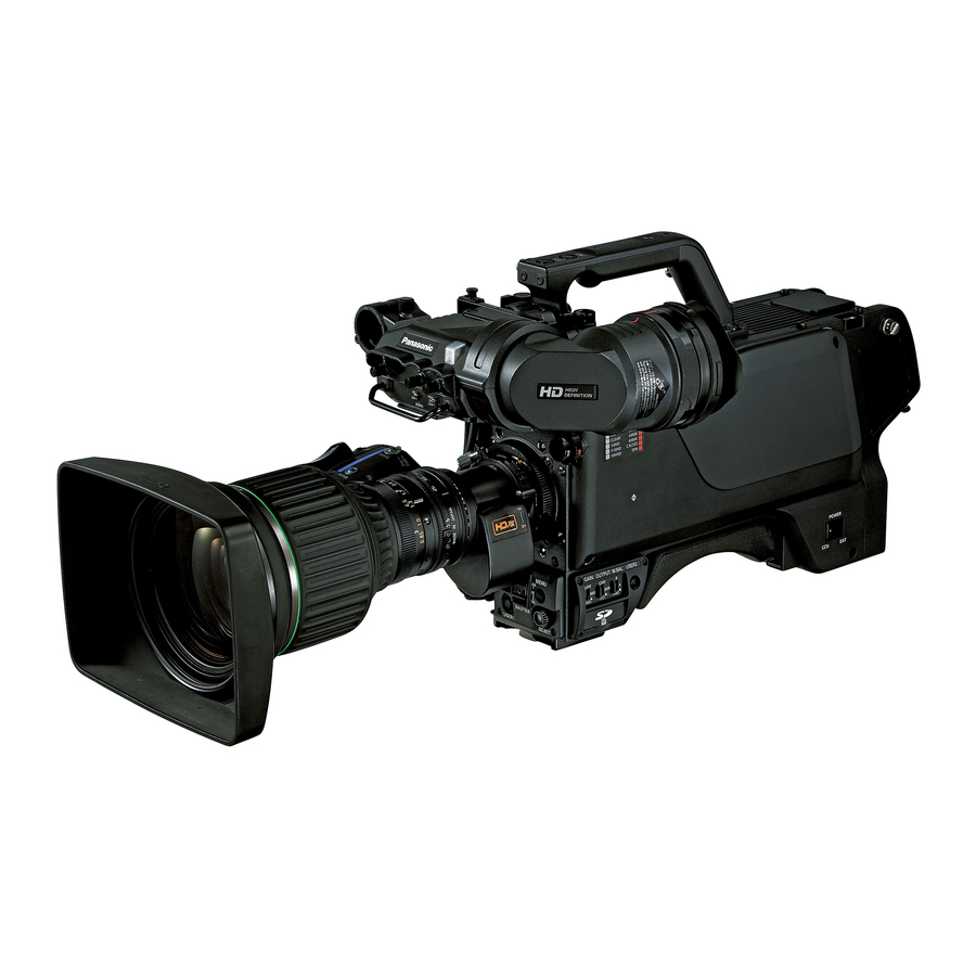
Operating Instructions Multi-Format Camera AK-HC3500P Model No. Before operating this product, please read the instructions carefully and save this manual for future use. VQTB0273-1... -
Page 2: For Your Safety
For your safety FCC Note: CAUTION This equipment has been tested and found to comply with the limits for a class A digital device, pursuant to RISK OF ELECTRIC SHOCK DO NOT OPEN Part 15 of the FCC Rules. These limits are designed to provide reasonable protection against harmful CAUTION: TO REDUCE THE RISK OF ELECTRIC SHOCK, interference when the equipment is operated in a... -
Page 3: Table Of Contents
For your safety IMPORTANT SAFETY INSTRUCTIONS Read these operating instructions carefully before using the unit. Follow the safety instructions on the unit and the applicable safety instructions listed below. Keep these operating instructions handy for future reference. 1) Read these instructions. 10) Protect the power cord form being walked on or pinched particularly... -
Page 4: Overview
The amount of heat generated by the camera has also been a significant margin over previous CCDs. Furthermore, slashed as a result of adopting a low-power-consumption Panasonic’s horizontal single-line readout CCD and design for the new circuits and a heat-dissipation design for high-precision signal processing combine to achieve pixel the new chassis. -
Page 5: Precautions For Use
Precautions for use DON’TS DO’S Do not attempt to disassemble the camera or other units. Refer any servicing to qualified service personnel. In order to prevent electric shock, do not remove screws or covers. There are no user-serviceable parts inside. ... -
Page 6: Controls And Their Functions
Controls and their functions... - Page 7 Controls and their functions...
-
Page 8: Controls And Their Functions
Controls and their functions Camera power switch [POWER] Lens mount (Bayonet type) This is where the lens is mounted. This is used to select the camera power input (power supplied from the CCU or from an external connector) ... - Page 9 Controls and their functions RET-A selector switch [RET A] Camera HD-SDI output1 connector (BNC) This switch is used to select the return images to be [HD-SDI1] switched by RET-A. The camera HD-SDI images are output from this The return images which have been set on the ROP connector.
- Page 10 Controls and their functions Rear MIC1 connector [MIC1] Filter local LED [LOCAL] An audio component or microphone is connected to this While this LED is lighted, the optical filter can be adjusted connector. manually. The gain setting can be selected on the camera menu. ...
- Page 11 SD memory cards whose operation has been authenticated (recommended) This light switch is used to make it easier to read the Cards made by Panasonic with a memory size of 2 GB characters on the camera’s back panel. or less (SD-HC memory cards are not supported) The brightness can be adjusted using the camera menu.
-
Page 12: Mounting The Lens
Mounting the lens Insert the cable into the cable clamp and connect it to Raise the lens clamp lever, and remove the mount cap. the lens connector. Lens connector Mount cap Lens clamp lever Notes For details on handling the lens, refer to the Align the guide pin on the lens with the groove at the instructions that accompany the lens. -
Page 13: Adjusting The Lens Flange Back
Adjusting the lens flange back Adjust the flange back (distance from the surface where the lens is mounted to the surface where the images are formed) if the subject fails to be precisely focused at both the telephoto and wide-angle settings when zoom operations are to be performed. Once adjusted, the flange back does not need to be adjusted again unless the lens is replaced. -
Page 14: Performing The Viewfinder Adjustments
Performing the viewfinder adjustments (The viewfinder is an optional accessory.) Attaching the viewfinder Detaching the viewfinder Check that the camera’s POWER switch is at the OFF Check that the camera’s POWER switch is at the OFF position. position. Pull up the knob on the mounting plate and slide the Loosen the stopper screw, pull up the knob on the plate to attach the viewfinder. - Page 15 Performing the viewfinder adjustments (The viewfinder is an optional accessory.) Left or right position adjustment Forward or backward position adjustment Loosen the stopper screw. Rotate the viewfinder forward/backward position fixing Stopper screw lever towards the outside to release it from the locked position.
-
Page 16: Connecting A Microphone
Connecting a microphone When the microphone is mounted on the viewfinder (optional accessory) for use A microphone such as the AJ-MC700 microphone kit (optional accessory) can be mounted on the viewfinder. If the audio channel whose signals are to be recorded Open the microphone holder. -
Page 17: Mounting The Camera On A Tripod
Mounting the camera on a tripod Use the tripod attachment, available as an optional Detaching the camera from the tripod attachment accessory, to mount the camera on a tripod. While pushing the red lever, move the black lever in the direction of the arrow, and slide the camera toward the back. -
Page 18: Component System Configuration
Component system configuration An example of the standard system consisting of the Multi-Format Camera (AK-HC3500) and peripheral components is described below and shown on the following page. The MSU (AK-MSU935) is not required unless a multiple number of cameras are to be controlled. The basic system configuration includes the lens, Multi-Format Camera, viewfinder, camera control unit (CCU) and remote operation panel (ROP). - Page 19 Component system configuration Outline of peripheral components Component connections Camera Control Unit (CCU: AK-HCU931) Refer to pages 20 to 22 for the component connections. After all the components have been connected (the monitor This is the Multi-Format Camera’s camera control unit. system may be connected afterward), set the CCU’s main It is connected to the Multi-Format Camera using an power switch to the ON position.
-
Page 20: System Connections 1 (With Multi-Format Camera)
System connections 1 (with Multi-Format Camera) 2˝ Electronic HD Viewfinder AJ-HVF21 Optical cable Camera Control Unit Lens AK-HCU931 Multi-Format Camera AK-HC3500 ROP cable Remote Operation Panel AK-HRP931 Before proceeding with the connections, set the CCU power switch to the OFF position. ... -
Page 21: System Connections 2 (With Buildup Unit)
System connections 2 (with Buildup Unit) Large lens Buildup Unit AK-HBU3500 8 LCD Viewfinder AK-HVF931A Optical cable Camera Control Unit AK-HCU931 Multi-Format Camera AK-HC3500 ROP cable Remote Operation Panel AK-HRP931... -
Page 22: System Connections 3 (With Msu)
System connections 3 (with MSU) Master Setup Unit AK-MSU935 Optical cable Camera Control Unit 1 Multi-Format Camera 1 AK-HCU931 AK-HC3500 Remote Operation Panel 1 AK-HRP931 Optical cable Camera Control Unit 11 Multi-Format Camera 11 AK-HCU931 AK-HC3500 Remote Operation Panel 11 AK-HRP931 Optical cable Camera Control Unit 12... -
Page 23: Status Displays On Viewfinder Screen
Status displays on viewfinder screen Filter display: Besides the images, Multi-Format Camera settings and This indicates the type of filter selected. messages indicating operating statuses appear on the viewfinder screen. White balance memory display: The camera menu VF DISPLAY screen and the items This indicates the automatic adjustment memory selected which have been set to ON using the switches related to the viewfinder display appear at the top and bottom of the... -
Page 24: Checking And Setting The Calendar
Checking and setting the calendar The calendar is checked and set on the [Date/Time] page located on the Maintenance menu. Checking the current settings Check the current year/month/day, day of the week and time displayed on [Present]. Select [Adjust], press the jog dial, and when [YES?] is selected and entered, the seconds are reset to “00.” ... -
Page 25: Menu Operations
Menu operations Entering the menu data Basic setting menu operations After accessing the item menus, enter the respective data. Displaying the menus Turn the JOG dial to select the menu item to be set. User menu Press the MENU switch. The camera’s USER menu screen now appears on the viewfinder or monitor. - Page 26 Menu operations Entering the menu data (continued) When the setting flashes one character at a time, press the JOG dial to move the flashing toward the right. When the JOG dial is pressed, flashing moves toward the right. Turn the JOG dial to change the setting. When the JOG dial is now pressed, the data is entered.
-
Page 27: Setting Menu Configuration
Setting menu configuration Hierarchical menus USER MENU... - Page 28 Setting menu configuration Hierarchical menus USER MENU...
- Page 29 Setting menu configuration Hierarchical menus USER MENU...
- Page 30 Setting menu configuration Hierarchical menus USER MENU...
- Page 31 Setting menu configuration Hierarchical menus USER MENU...
-
Page 32: Table Of Adjustment Setting Ranges
Table of adjustment setting ranges Operation Menu Item Adjustment setting range Initial value Items recorded on SD memory cards VF Setting1 No switching from the SD memory Side Modu SW OFF, ON card to the camera settings possible while the buildup unit is connected. ... - Page 33 Table of adjustment setting ranges Menu Item Adjustment setting range Initial value Items recorded on SD memory cards Setting1 HD-SDI2 OUT MAIN, VF, RET HD-SDI2 Power ACTIVE, SAVE ACTIVE AUX I/O RET Y IN, PMT2 OUT, VBS OUT, D1 OUT RET Y IN TRUNK1 RS422, RS232C...
- Page 34 Table of adjustment setting ranges Painting Menu Item Adjustment setting range Initial value Setting SW Flare OFF, ON Black Gamma OFF, ON Gamma OFF, ON Knee OFF, ON White Clip OFF, ON Matrix OFF, ON Preset Matrix NORM, EBU, NTSC NORM OFF, ON Skin Tone DTL...
- Page 35 Table of adjustment setting ranges Menu Item Adjustment setting range Initial value Linear Matrix Matrix OFF, ON Linear OFF, A, B 12axes OFF, A, B –31 to +31 –31 to +31 –31 to +31 –31 to +31 –31 to +31 –31 to +31 Color Correct1 Matrix...
- Page 36 Table of adjustment setting ranges Menu Item Adjustment setting range Initial value Skin Tone Detail1 Skin Tone DTL OFF, ON Skin Tone Get EXECUTE (execution items) EXECUTE Skin Tone Get CANCEL (execution items) CANCEL MEM Select A, B Cursor OFF, ON H Cursor 1 to 1920 V Cursor...
- Page 37 Table of adjustment setting ranges Maintenance Menu Item Adjustment setting range Initial value Date / Time (*4) Present (Display item) (Current date/time) Adjust NO?, YES? 12H, 24H 24H, 12H Date YY Year (Current year) Date MM Month (Current month) Date DD (Current day) Date aaa Day of week...
- Page 38 Table of adjustment setting ranges Menu Item Adjustment setting range Initial value CINE Gamma Cinema Gamma SW OFF, ON Cinema Gamma SEL VIDEO_REC, FILM_REC VIDEO_REC Black STR LVL 0 to +30 Dynamic LVL 200 %, 300 %, 400 %, 500 % 200 % Knee Point +30 to +90...
-
Page 39: Sd Memory Card Operations
SD memory card operations These operations are performed on the SD Card page on the Maintenance menu. The VF display settings and camera function settings on the Operation menu can be recorded on the SD memory card. For details on what items are stored in the memory of the SD memory card, refer to “Table of the adjustment setting ranges.” Mode: SD memory card operation mode setting Select the SD memory card operation here. -
Page 40: Ak-Hc3500 Connector Pin Assignment
AK-HC3500 connector pin assignment CN# in the CN# in the CN# in the Instructions Instructions Instructions OPT FIBER EDW.3K.93C.TLC (LEMO) MIC1 HA16PRM-3SB(05) (Hirose) REAR VF CN D02-29S-N-F0 (JAE) Pin# Signal Pin# Signal Pin# Signal MIC1_GND VF-YOUT OPT-TX (Mark Band = IN) MIC1(H) VF-PBOUT OPT-RX (Mark Band = OUT) -
Page 41: External Dimension Drawings
External dimension drawings Unit: inch (mm) 5-5/16 (135) 14-3/16 (360) -
Page 42: Specifications
Specifications 3) HD-SDI1/HD-SDI2 output: Power supply: DC 12 V HD signal = 0.8 Vp-p, 75 ohms (BNC) (when external power is supplied) The HD-SDI2 signal output can be AC 150 V - 240 V added to the regular images using the (when CCU is connected) camera menu item setting and switched Power consumption: 28 W (during external power... - Page 43 Memo...
- Page 44 PANASONIC BROADCAST & TELEVISION SYSTEMS COMPANY UNIT COMPANY OF PANASONIC CORPORATION OF NORTH AMERICA Executive Office: One Panasonic Way 4E-7, Secaucus, NJ 07094 (201) 348-7000 EASTERN ZONE: One Panasonic Way 4E-7, Secaucus, NJ 07094 (201) 348-7621 Southeast Region: 1225 Northbrook Parkway, Ste 1-160, Suwanee, GA 30024 (770) 338-6835...