
Related Manuals for Trane Tracer ZN.520


Summary of Contents for Trane Tracer ZN.520
- Page 1 Installation Owner Diagnostics Tracer ZN.520 for Classroom ® Unit Ventilator UV-SVP01A-EN...
-
Page 2: Start-Up Procedures
ZN.520 unit controller. 7. Check for YELLOW Comm LED operation to help ensure com- munication has been made to the Tracer ZN.520 unit control- ler when required. Peel IDENTIFICATION TAG from unit and place in the Appendix of this document, or on building plans for future location use. -
Page 3: Power-Up Sequence
Start-up Procedures Power Up Sequence Manual output test can be initiated at any time in the power up se- quence or during normal opera- tion. When 24 VAC power is initially ap- plied to the controller, the follow- ing sequence occurs: 1. -
Page 4: General Information
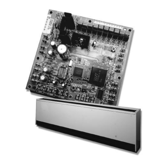
® system will provide a complete building management system. The stand-alone control package Figure 1: Tracer ZN.520 Control Board offers the features and function- ality of the direct digital control without a front-end building au- The Tracer ZN.520 is factory-... - Page 5 General Information Table 1: Tracer™ ZN.520 Unit Controller features and coil availability Entering Auto Face and Multiple Dehumid- Valve Economizer Auxiliary Water Coil Damper Bypass Fan Speeds ification Control Damper Heat Temperature Adjust Damper Sampling 2-pipe changeover 2-pipe hot water only 2-pipe steam only 2-pipe changeover/...
- Page 6 Controller Circuit Board Features Power Generic Auto Test Button Status LED Communications LED Service Button and LED Communications Zone Sensor Connections Figure 2: Tracer ZN.520 unit controller circuit board UV-SVP01A-EN...
-
Page 7: Controller Features
The zone sensor may also be used circuit board is equipped with en- when trying to locate a unit. By hancements to help facilitate ser- The Trane Tracer ZN.520 unit con- pressing the button on the zone vice, testing, and diagnosis. -
Page 8: Communication Configurations
Communication Configurations Note: The Tracer ZN.520 is a connect to a maximum of 120 The ICS system also allows all of configured controller. It will Tracer ZN.520 controllers. the classroom unit ventilators to not operate without a valid share information without the... -
Page 9: Stand-Alone
Note: Refer to the Tracer Rover allows the user to interface Tracer ZN.520 to index the unit system manuals for more with the Tracer ZN.520, but will not information on communica- between occupied and allow any advanced control (e.g. tions. - Page 10 Standard End Devices Table 2: End Device Specifications Device Characteristic Description Fan Status Switch Material Contact Blade—Pilot duty rated Operating Temperature Range -40°F/250°F (-40°C/120°C) Contact Form SPST-NO Preset Fan status - 0.07” Low Temperature Detection Switch (Freezestat) 3 6 ° F ± 2 ° F Trip Temperature: (2°C + - 1.11°C) 4 4 °...
- Page 11 Standard End Devices Table 2: End Device Specifications Device Characteristic Description Outside Air Actuator Description Three-point floating with spring return Ambient Temperature Rating -25°F to 125°F Power Consumption 5 VA Torque 35 in-lbs. Drive Time 90 seconds, 95 degree stroke Face and Bypass Actuator Description Three-point floating...
- Page 12 Standard End Devices Table 2: End Device Specifications Device Characteristic Description 3-way Control Valve Description Three-point modulating Ambient Temperature Rating 140°F at 95% relative humidity Drive Time 50 seconds Max Pressure 400 psi water Close Off Varied by size and Cv Temperature Water 200°F maximum Time clock...
- Page 13 Standard End Devices Table 2: End Device Specifications Device Characteristic Description Humidity Sensor Sensing Element Polymer capacitive Sensing Element Accuracy: ± 5% over 20-95% RH @ 77ºF Range 0 to 99% RH Operating Temperature Range 0°F to 140ºF Max Supply Voltage 24VDC Output Characteristics 4 to 20 MA for 0-100% RH...
- Page 14 Standard End Devices Table 2: End Device Specifications Device Characteristic Description Type N.E.C. Class 2 Primary Voltage 120 vac Control Transformer 24 vac at 90 va Secondary voltage Manual reset 4amp fuse in 24-volt circuit UV-SVP01A-EN...
-
Page 15: Installation And Wiring
-40° to 185°F (-40° to 85°C) • 5% to 95% relative humidity, non-condensing Agency Listings • UL and CUL 916 Energy Man- agement System • Agency Compliance IEC 1000- 4-2 (ESD), IEC 1000-4-4(EFT), IEC 1000-4-5 (Surge) Figure 7: Tracer ZN.520 circuit board schematic UV-SVP01A-EN... -
Page 16: Binary Inputs
Installation and Wiring Binary Inputs Each binary input associates an in- put signal of 0 VAC with open con- tacts and 24 VAC with closed contacts. Table 3: Binary inputs (typically 24 mA AC) Description Terminals Terminal Function Binary input 1 J2-1 24 VAC (BI 1) -
Page 17: Binary Outputs
Installation and Wiring Binary Outputs Outputs are load side switching tri- acs. The triac acts as a switch, ei- ther making or breaking the circuit between the load (valve, damper, contactor, relay) and ground. Table 4: Binary outputs Output Description Terminals Load Energized Load De-energized... -
Page 18: Analog Inputs
Installation and Wiring Analog Inputs Table 6: Analog inputs Description Terminals Function Range Zone TB3-1 Space temperature input 5 to 122 F (-15 to 50 C) Ground TB3-2 Analog ground TB3-3 Setpoint input 40 to 115 F (4.4 to 46.1 C) TB3-4 Fan switch input 4821 to 4919... - Page 19 Installation and Wiring Mounting The Tracer ZN.520 circuit board is mounted in the left-hand end pock- et for all classroom unit ventilator configurations. The sheet metal mounting plate has raised emboss- es to accept the mounting feet on the circuit board. (See Figure 8: “Classroom unit ventilator control...
- Page 20 Tracer ZN.520 by re- slide out with the removal of a sin- board and mounting plate. (See moving the front panel. (See gle screw for complete access to Figure 11: “Quick connects to con-...
- Page 21 24 VAC connection to the wires up to 16 AWG is board. inside of the unit's access recommended for bending and panel for specific wiring infor- forming wires. Figure 12: Power connection to the Tracer ZN.520 unit controller UV-SVP01A-EN...
- Page 22 Installation and Wiring Installing the Wall- Note: It may be necessary to q Near radiant heat (e.g., heat subdivide the zone with emitted from appliances or the Mounted Zone Sensor multiple units to ensure sun); (Optional) adequate control and comfort q Near concealed pipes or throughout the space.
- Page 23 Installation and Wiring Humidity and CO Sensors Humidity and CO sensors should be mounted in a similar location as the zone sensor. Figure 14: Relative humidity sensor Figure 15: CO Sensor UV-SVP01A-EN...
- Page 24 Typical Wiring Diagram—Wall Mounted Zone Sensor UV-SVP01A-EN...
- Page 25 Typical Wiring Diagram—Unit Mounted Zone Sensor UV-SVP01A-EN...
-
Page 26: Typical Wiring Diagram
Typical Wiring Diagram— Unit Mounted Switch, Wall Mounted Sensor UV-SVP01A-EN... -
Page 27: Input/Output Summary
Input/Output Summary Input/Output Summary Most binary inputs and outputs are must be wired to the 1/4” quick- wired from the factory based on connect terminals provided. Most The following lists all possible bi- unit configuration and options. If other analog inputs will be wired nary and analog inputs and out- the generic inputs and outputs are from the factory. - Page 28 Input/Output Summary Table 8: Input and output summary Input Description Zone Temperature Setpoint Fan Speed Entering Water Temperature Analog Inputs Discharge Air Temperature Outdoor Air Temperature/ Generic Generic/Humidity/CO2 (4- 20mA) UV-SVP01A-EN...
-
Page 29: Configurable Parameters
Configuration Note: The Tracer Zn.520 unit Trane configures the Tracer and 2 -stage electric heat, face- ® controller only supports ZN.520 Unit Controller at the fac- and-bypass damper, baseboard cascade control by controlling tory per the selected unit configu- heat, dehumidification, and ge- the discharge air temperature. - Page 30 TB4-2 1. Trane’s Rover service tool uses the unit type to determine and download the proper default binary output configuration. 2. The normally open/closed configuration item refers to the inactive state of the controlled end device (such as an 2-position cooling valve output).
- Page 31 Normally open BI 4 Fan status or not used Normally closed 1. Trane Rover service tool uses the unit type to determine and download the proper default binary input configuration. Analog Inputs Table 12: Analog input summary Analog input Configuration Calibration range +/- 10.0°F...
-
Page 32: Fan Configuration
Configuration Fan Configuration Table 13: Fan configuration ranges Fan configuration Default Valid range Continuous (during occupied) Fan operation in heating Continuous Cycling with capacity (unoccupied) Continuous (during occupied) Fan operation in cooling Continuous Cycling with capacity (unoccupied) Number of fan speeds Varies 1, 2 Configurable fan speed heating... -
Page 33: Freeze Avoidance
Configuration Setpoints Table 15: Setpoint defaults Setpoint Default Valid range Occupied heating setpoint 71 F 40 to 115 F Occupied cooling setpoint 74 F 40 to 115 F Occupied standby heating setpoint 67 F 40 to 115 F Occupied standby cooling setpoint 78 F 40 to 115 F Unoccupied heating setpoint... - Page 34 Configuration Occupied Bypass Timer Table 18: Bypass timer range Default Valid range 0 to 240 minutes Occupancy bypass timer 120 Minutes (1 minute resolution) 1. The occupied bypass timer is used for timed override applications. Power-Up Control Wait Table 19: Control wait timer Default Valid range Power up control wait (2 minutes)
-
Page 35: Location Identifier
English description. ond for approximately 10 seconds. A Tracer ZN.520 unit controller If location identification is not de- This feature is useful when a dis- may be set to wink by fined, it will default to the unit seri- crepancy in device location exists. -
Page 36: Unit Operation
OCC UPIED controller can be placed in OC CU q The controller reads input mode of the Tracer ZN.520 control- mode by either com- values to determine initial PIE D BYPASS ler. municating an occupancy request values. - Page 37 Unit Operation 4 = Night Purge (air 9 = Fan Only (no heating or perature) is (900 FhSec). Integra- changeover) not supported cooling allowed) tion only begins once the heating and cooling capacity is equal to 0% 5 = Pre-cool (morning cool All other enumerations will be in- or the discharge air temperature is down)
-
Page 38: Fan Off Delay
For multiple fan speed applica- Fan Speed Absolute tions, the Tracer ZN.520 controller Change Temperature Error allows separate default fan speeds Cooling Operation to be configured for heating and °F... -
Page 39: Valve Operation
Modulating Valves Face-and-bypass units may use isolation valves to prevent unwant- Exhaust fan/damper The Tracer ZN.520 controller sup- ed water flow in the coil. This elim- operation ports one or two modulating inates problems such as radiant... -
Page 40: Entering Water Temperature Sampling
The sition from Tracer Summit. A com- Tracer ZN.520 controller has a wa- municated minimum position ter sampling feature for these ap- from Tracer Summit has priority plications. -
Page 41: Economizer Operation
Damper Adjustment Operation The Tracer ZN.520 controller con- forms to ASHRAE Cycle II by allow- The Tracer ZN.520 controller is ca- The Tracer ZN.520 controller sup- ing the modulating outdoor air pable of using different minimum ports 1 or 2 stages of electric heat... -
Page 42: Output Overrides
2. The Tracer ZN.520 controller ventilation. tive humidity setpoint is valid. has a binary input available The exhaust fan is disabled when... - Page 43 COOL DOW N the outdoor air temperature rises control. The Tracer ZN.520 controller keeps 3°F above the freeze avoidance Data sharing is established the modulating outdoor air damp- setpoint. through the use of “bindings”.
- Page 44 Unit Operation Figure 24: More complex data sharing application UV-SVP01A-EN...
- Page 45 OCC UPIED controller can be placed in OC CU q The controller reads input mode of the Tracer ZN.520 control- mode by either com- values to determine initial PIE D BYPASS ler. municating an occupancy request values.
- Page 46 Unit Operation 4 = Night Purge (air 9 = Fan Only (no heating or perature) is (900 FhSec). Integra- changeover) not supported cooling allowed) tion only begins once the heating and cooling capacity is equal to 0% 5 = Pre-cool (morning cool All other enumerations will be in- or the discharge air temperature is down)
- Page 47 For multiple fan speed applica- Fan Speed Absolute tions, the Tracer ZN.520 controller Change Temperature Error allows separate default fan speeds Cooling Operation to be configured for heating and °F...
- Page 48 Modulating Valves Face-and-bypass units may use isolation valves to prevent unwant- Exhaust fan/damper The Tracer ZN.520 controller sup- ed water flow in the coil. This elim- operation ports one or two modulating inates problems such as radiant...
- Page 49 The sition from Tracer Summit. A com- Tracer ZN.520 controller has a wa- municated minimum position ter sampling feature for these ap- from Tracer Summit has priority plications.
- Page 50 Damper Adjustment Operation The Tracer ZN.520 controller con- forms to ASHRAE Cycle II by allow- The Tracer ZN.520 controller is ca- The Tracer ZN.520 controller sup- ing the modulating outdoor air pable of using different minimum ports 1 or 2 stages of electric heat...
- Page 51 2. The Tracer ZN.520 controller ventilation. tive humidity setpoint is valid. has a binary input available The exhaust fan is disabled when...
- Page 52 COOL DOW N the outdoor air temperature rises control. The Tracer ZN.520 controller keeps 3°F above the freeze avoidance Data sharing is established the modulating outdoor air damp- setpoint. through the use of “bindings”.
- Page 53 Unit Operation Figure 24: More complex data sharing application UV-SVP01A-EN...
-
Page 54: Troubleshooting
Troubleshooting Yellow Comm LED Important! When viewing the The Service push button, located Tracer ZN.520 through the at the bottom center of the control- Rover service tool, it is ler, can be used to install the Trac- The yellow Comm LED blinks at the important that the version be er™... -
Page 55: Test Procedure
Troubleshooting If a two-blink pattern remains after release the button to start the Alternatively, the manual output an attempt to clear diagnostics, test mode. test can be controlled over the the diagnostic condition is still communications network by using 2. When manual output test present and may affect the manual Rover. - Page 56 Troubleshooting Table 27: Test sequence for face-and-bypass unit configurations Generic/ DX, or cool or heat/ Face-and- Electric heat, Outdoor air Step baseboard cool changeover valve bypass damper or heat valve damper heat J1-1 J1-2 J1-3 J1-5 J1-6 J1-7 J1-8 J1-9 J1-10 J1-11 J1-12...
- Page 57 Configuration neric analog input failure diagnos- tic occurs. If the Tracer ZN.520 has validated If the Tracer ZN.520 has been con- a space temperature input and figured improperly or loses its then the input becomes invalid, a configuration, an invalid unit con-...
- Page 58 Troubleshooting Diagnostics Table 28: Tracer™ ZN.520 Unit Controller diagnostics Latching/non- Diagnostic Unit Response Reset latching Fan— Auto reset once within 24hrs. If Valves— OPEN safety generates a diagnostic Low Coil Temperature Outdoor air damper— CLOSED Latching more than once a communi- Detect Face bypass damper—...
- Page 59 Troubleshooting Table 28: Tracer™ ZN.520 Unit Controller diagnostics Latching/non- Diagnostic Unit Response Reset latching Fan— ENABLED Valves— ENABLED Outdoor air damper— ENABLED Humidity Input Failure Non-latching Communicated or manual reset Face bypass damper— ENABLED DX/electric heat— ENABLED Baseboard heat— ENABLED Fan—...
- Page 60 Troubleshooting Table 28: Tracer™ ZN.520 Unit Controller diagnostics Latching/non- Diagnostic Unit Response Reset latching Fan— DISABLED Valves— DISABLED Outdoor air damper— DISABLED Invalid Unit Configuration Non-latching Communicated or manual reset Face bypass damper— DISABLED DX/electric heat— DISABLED Baseboard heat— DISABLED Fans—E NABLED Valves—...
-
Page 61: Questionable Unit Operation
However, based on the current step in the test sequence, the unit fan may not be on. For more information see, Manual Output Test, on page 48 for more information.) When a local fan mode switch (provided on the Trane zone sensor) determines the fan operation, the Fan mode OFF... - Page 62 However, based on the current step in the test sequence, the valve(s) may not be open. For more information see, Manual Output Test, on page 48 for more information.) When a local fan mode switch (provided on the Trane zone sensor) determines the fan operation, the Fan mode off off position controls the unit off and valves to close.
- Page 63 However, based on the current step in the test sequence, the unit damper may not be open. For more information see, Manual Output Test, on page 48 for more information.) When a local fan mode switch (provided on the Trane zone sensor) determines the fan operation, the Fan mode position controls the unit and damper to close.
- Page 64 Troubleshooting Table 33: Outdoor air damper stays closed Probable cause Explanation You can communicate a desired operating mode (such as , and ) to the controller. When HEAT COOL Requested mode is communicated to the controller, the unit controls the fan .
-
Page 65: Replacing Circuit Boards
Replacing Circuit Boards Tracer ZN.520 Unit Controller Replacement Disconnect power or disable the circuit breaker to unit. 2. Remove bad or questionable Tracer ZN.520 controller cir- cuit board. 3. Install controller in the unit with the heat-sink placement at the top of the control box. - Page 66 Appendix Hardwired Setpoint Adjustment Table 35: Hardwired setpoint adjustment Resistance ( ) Setpoint (Deg F) 889.4 733.6 577.9 422.1 344.2 266.4 188.5 110.6 Fan Switch Resistance Values Table 36: Resistance values Resistance ( ) Switch Position 16,300 High 10,700 2,320 Auto 4,870 Hardwired Thermistor Values...
-
Page 67: Appendix-Binary Configuration
Appendix—Binary Configuration Binary Configuration Table 38: Binary configuration details Binary input Function Configuration Description or output Low temp Closed: BIP 1 is Normal (no diagnostic) BI 1 Normally closed detection Open: BIP 1 is Active (diagnostic) Condensate Closed: BIP 2 is Normal (no diagnostic) BI 2 Normally closed overflow... -
Page 68: Appendix-Unit Operation
Appendix—Unit Operation Unit Operation Based On The Effective Output HEAT COOL Table 39: Unit operation based on the effective heat/cool output Effective heat/ cool Application mode input Heat/cool mode input mode output Unit Operation (nviApplicMode) (nviHeatCool) (nvoHeatCool) Fan—Enabled Heating—Enabled Auto Determined by controller Cooling—Enabled Damper—Enabled... - Page 69 Appendix—Unit Operation cont. Table 39: Unit operation based on the effective heat/cool output Effective heat/ cool Application mode input Heat/cool mode input mode output Unit Operation (nviApplicMode) (nviHeatCool) (nvoHeatCool) Cool Any state Cool Fan—Enabled Heating—Disabled Cooling—Enabled Damper Pre-cool Any state Pre-cool Fan—Enabled Heating—Disabled...
-
Page 70: Appendix-Data Lists
Appendix—Data Lists Data Lists Table 70 provides an input/output listing for the Tracer ZN.520 unit controller. The content of the lists conforms to both the LonMark Space Comfort Controller Functional Profile and the LonMark node object. Table 40 Input/output listing... -
Page 71: Setting The Time Clock
Appendix—Timeclock Setting the Time The following procedure covers: Clock q setting the current time and The time clock must be pro- q setting the program (events) grammed for the unit to operate q reviewing and changing the in occupied mode (under load). If programs, and not programmed, the unit will run in the unoccupied mode. -
Page 72: Manual Operation
Appendix—Timeclock the unit will respond differently to a half hour or so before the during any day or combination changing conditions and maintain arrival of people, so the unit of days (up to 20 events) a higher comfort level. will bring the room up (or 9. - Page 73 Appendix—Timeclock To switch the load permanently OFF, press the key a third time. [O] appears in the display. To return to automatic (pro- grammed) operation, press the key a fourth time. Run appears ¹ in the display. NOTE: The Main Power Disconnect switch is located on the lower right side of the unit behind the right front...
-
Page 74: Appendix-Location Identifier
Appendix—Location Identifier This area provided for the removable tag. UV-SVP01A-EN... -
Page 75: Location Identifier
Location Identifier UV-SVP01A-EN... - Page 76 Location Identifier UV-SVP01A-EN...
- Page 77 Location Identifier UV-SVP01A-EN...
- Page 78 The Trane Company Stocking Location La Crosse Worldwide Applied Systems Group LaCrosse, Wisonsin www.trane.com Since The Trane Company has a policy of continuous product improvement, it reserves the right to change design and specifications without notice. An American Standard Company...
Need help?
Do you have a question about the Tracer ZN.520 and is the answer not in the manual?
Questions and answers