AOpen AX4B-533 Tube Online Manual
Hide thumbs
Also See for AX4B-533 Tube:
- Online manual (109 pages) ,
- Easy installation manual (9 pages) ,
- Installation manual (9 pages)

Related Manuals for AOpen AX4B-533 Tube


Summary of Contents for AOpen AX4B-533 Tube
-
Page 1: Ax4B-533 Tube
AX4B-533 Tube DOC. NO.: AX4B533Tube-OL-E0206A... -
Page 2: Table Of Contents
’ ’ AX4B-533 Tube ..........................1 What’s in this manual ..............................2 You Must Notice ................................9 Before You Start ................................10 Overview ..................................11 Feature Highlight................................12 Quick Installation Procedure ............................16 Motherboard Map ................................17 Block Diagram................................18 Hardware Installation........................ - Page 3 DIMM Sockets ................................31 Front Panel Connector ..............................33 ATX Power Connector ..............................34 STBY LED and BOOT LED ............................35 AC Power Auto Recovery .............................. 36 IDE and Floppy Connector ............................37 IrDA Connector ................................39 AGP (Accelerated Graphic Port) Expansion Slot ......................40 AGP Protection Technology............................
- Page 4 Front Audio Connector ..............................53 Tube Necessary components ............................54 JP3 Tube Power Jumper ............................... 55 Super 5.1 Channel Audio Effects........................... 56 Dr. Voice II (Volume adjustable through speaker)......................57 JP1 Buzzer and JP2 Speaker Enable/Disable Jumper ....................58 Battery-less and Long Life Design..........................59 CPU Over-current Protection............................
- Page 5 BIOS Upgrade under Windows environment ......................... 94 Overclocking..........................96 VGA Card & Hard Disk ..............................97 Glossary ............................ 98 AC97 ..................................... 98 ACPI (Advanced Configuration & Power Interface) ....................... 98 AGP (Accelerated Graphic Port)............................ 98 AMR (Audio/Modem Riser)............................99 AOpen Bonus Pack CD ..............................99...
- Page 6 APM (Advanced Power Management) ........................... 99 ATA (AT Attachment) ..............................99 ATA/66 ..................................99 ATA/100 ..................................100 ATA/133 ..................................100 BIOS (Basic Input/Output System) ..........................100 Bus Master IDE (DMA mode) ............................101 CNR (Communication and Networking Riser)......................101 CODEC (Coding and Decoding) ..........................101 DDR (Double Data Rated) SDRAM ..........................
- Page 7 Flash ROM .................................. 104 FSB (Front Side Bus) Clock ............................104 C Bus ..................................104 IEEE 1394 ................................... 105 Parity Bit ..................................105 PBSRAM (Pipelined Burst SRAM)..........................105 PC-100 DIMM ................................106 PC-133 DIMM ................................106 PC-1600 or PC-2100 or PC-2700 DDR DRAM ......................106 PCI (Peripheral Component Interface) Bus .........................
- Page 8 SPD (Serial Presence Detect) ............................. 109 Ultra DMA ................................... 109 USB (Universal Serial Bus) ............................109 VCM (Virtual Channel Memory) ........................... 110 ZIP file..................................110 Troubleshooting........................111 Technical Support ........................115 Product Registration ....................... 118 How to Contact Us ........................119...
-
Page 9: You Must Notice
All of the specifications and information contained in this manual are subject to change without notice. AOpen reserves the right to revise this publication and to make reasonable changes. AOpen assumes no responsibility for any errors or inaccuracies that may appear in this manual, including the products and software described in it. -
Page 10: Before You Start
This Online Manual will introduce to the user how this product is installed. All useful information will be described in later chapters. Please keep this manual carefully for future upgrades or system configuration changes. This Online Manual is saved format, we recommend using Adobe Acrobat Reader 4.0 for online viewing, it is included in Bonus CD disc or you can get free download from... -
Page 11: Overview
® Thank you for choosing AOpen AX4B-533 Tube motherboard. The AX4B-533 Tube is Intel Socket 478 motherboard (M/B) based on the ATX form factor featuring the Intel® 845E (Brookdale) chipset. As high performance chipset built in the M/B, the ®... -
Page 12: Feature Highlight
1056MB/s. AX4B-533 Tube motherboard includes one 1.5V AGP expansion slot with 4x SBA/Data Transfer and 2x/4x Fast Write capability. For AD and SBA signaling, AX4B-533 Tube motherboard can support 4X mode. Of three PCI slots provided, all of them are master PCI slots with arbitration and decoding for all integrated functions and LPC bus. - Page 13 Ultra DMA 33/66/100, PIO Modes 3 and 4 and Bus Master IDE DMA Mode 5, and supports Enhanced IDE devices. On-board AC’97 Sound AX4B-533 Tube uses the Real Tek ALC650 AC97 sound chip. This on-board audio includes a complete audio recording and playback system.
- Page 14 100~248 by 1MHz stepping adjustment, and lets your system can get maximum performance. Watch Dog Timer Includes AOpen “Watch Dog Timer” function that can auto-reset system in 4.8 seconds when you fail to system over clocking. Six USB2.0 Conne...
- Page 15 Power Management/Plug and Play Supports the power management function that confirms to the power-saving standards of the U.S. Environmental Protection Agency (EPA) Energy Star program. It also offers Plug-and-Play, which helps save users from configuration problems, thus making the system much user-friendlier. Hardware Monitoring Management Supports CPU or system fans status, temperature and voltage monitoring and alert, through the on-board hardware monitor module.
-
Page 16: Quick Installation Procedure
This page gives you a quick procedure on how to install your system. Follow each step accordingly. Installing CPU and Fan Installing System Memory (DIMM) Connecting Front Panel Cable Connecting IDE and Floppy Cable Connecting ATX Power Cable Connecting Back Panel Cable Power-on and Load BIOS Setup Default Setting CPU Frequency Reboot... -
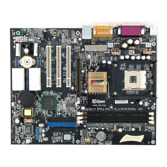
Page 17: Motherboard Map
therboard Map Front A udio Connector CD-IN Connector Onboard AC’97 CODEC PC99 Colored Back Panel A X-IN Connector Tube dio Connector Resetable Fuse (Line-in/RCA/H hone/S/PDIF) JP28 Keyboard/Mouse Wakeup Enable/Disable Jumper 32-bit PCI E sion Slot x3 4-pin 12V. ATX Power Connector Sovtek 6922 D Triode Tube 2200μF Low ESR Capacitors... -
Page 18: Block Diagram
PC-200/2 66 DDR SDRAM Up to 2GB 32-bit PCI Slot x3 DIMM Socket x3 Socket 478 400/533MHz Intel System Bus ntium 4 PCI Bus Intel 845E Primary 33/66100 Channel IDE Driv e x4 AGP 4X Slot Secondary Channel AC97 CODEC ICH4 Intel 82562ET/EM... -
Page 19: Hardware Installation
This cha pter describes jumpers, connectors and hardware devices of this motherboard. Note: Electrostatic discharge (ESD) can damage your processor, disk drives, expansion board s, and other components. Always observe the following precautions before you install a system compon ent. Do not remove a component from its protective packaging until you are ready to install it. -
Page 20: About "Manufacturer Upgrade Optional" And "User Upgrade Optional
“User Upgrade Optional”. As for those optional functions that can’t be upgraded by ourselves, we call them “ Manufacturer Up Optional”. If needed, you can contact our local distributors or resellers for purchasing “User Upgrade Optional” compon and again you can visit AOpen official web site: www.aopen.com for more detail information. -
Page 21: Jp14 Clear Cmos Data
You can clear CMOS to restore system default setting. To clear the CMOS, follow the procedure below. Turn off the system and unplug the AC power. Remove ATX power cable from connector PWR2. Locate JP14 and short pins 2-3 for a few seconds. Return JP14 to its normal setting by shorting pin 1 &... - Page 22 ® This motherboard supports Intel Pentium 4 Socket 478 series CPU. Be careful of CPU orientation w hen you plug it into CPU socket. Locate Pin 1 in the socket and look for a cut edge on the CPU upper 1.
-
Page 23: Cpu Installation
3. Press down the CPU socket lever and finish CPU installation. CPU cut edge Note: If you do not match the CPU socket Pin 1 and CPU cut edge well, it may damage the CPU. Note: This socket supports icro-FC-PGA2 package CPU, which is the latest CPU package developed Intel. - Page 24 CPU socket when shipped, we strongly recommend you to erboard comes with a retention module attached on the CPU socket when shipped, we strongly recommend you to nstall AOpen nstall AOpen special designed CPU Fan as shown below on the retention module for better heat dissipation.
-
Page 25: Cpu Jumper-Less Design
CPU VID signal and SMbus clock generator provide CPU voltage auto-detection and allows the user to set the CPU frequency through the BIOS setup, therefore no jumpers or switches are used. The disadvantages of the Pentium based jumper-less designs are eliminated. There will be no worry of wr n o g CPU voltage detection. - Page 26 “ ” “ ” With this motherboard, AOpen provides a very special, useful feature for overclockers. When you power-on the system, the BIOS will check last system POST status. If it succeeded, the BIOS will enable “Watch Dog Timer” function immediately, and set the CPU frequency by user’s setting...
-
Page 27: Full-Range Adjustable Cpu Core Voltage
Tip: If your system hangs or fails to boot because of Home overclocking, simply use <Home> key to restore the default setting or you can wait the AOpen “Watch Dog Timer” reset the system after five seconds and system will auto-detect hardware again. - Page 28 Core Frequency = CPU Clock * CPU Ratio PCI Clock = CPU FSB Clock / Clock Ratio Clock = PCI Clock x 2 Willamette CPU Core System Northwood CPU Core System Ratio Ratio Frequency Clock Frequency Clock Pentium 4 Pentium 4 1500MHz 100MHz 400MHz...
-
Page 29: Cpu And System Fan Connector (With H/W Monitoring)
Plug in the CPU fan cable to the 3-pin CPU FAN co nnector. If you have chassis fan, you can also plug it on System Fan (FAN2) or FAN3 (AUX Fan) connector. +12V SENSOR FAN2 Connector SENSOR CPU Fan Connector +12V SENSOR Note: Some CPU fans do not have... -
Page 30: Jp28 Keyboard/Mouse Wake-Up Enable/Disable Jumper
This motherboard provides keyboard / mouse wake-up function. You can use JP28 to enable or disable this function, which could resume your system from suspend mode with keyboard or mouse installed. The factory default setting is set to “Disable”(1-2), and you may en able this function by set ting the jumper to 2-3. -
Page 31: Dimm Sockets
This motherboard has three 184-pin DDR DIMM sockets that allow you to install PC200 PC266 memory up to 2 GB. Both ECC and Non-ECC DDR SDRAM are supported, but you can’t install them both on DIMM. Otherwise, it will cause serious damage on memory sockets or SDRAM module. - Page 32 Please follow the procedure a s shown below to finish memory installation. Make sure the DIMM module’s pin face down and match the socket’s size as depicted below. 40 pins 52 pins Insert the module straight down to the DIMM slot with both hands and press down firmly until the DIMM module is securely in place.
-
Page 33: Front Panel Connector
Attach the power LED, Keylock, speaker, power and reset switch connectors to the corresponding pins. If you enable “S uspend Mode” item in BIOS Setup, the ACPI & Power LED will keep flashing while the system is in suspend mode. Locate the power switch cable from your ATX housing. -
Page 34: Atx Power Connector
This motherboard comes with a 20-pin and 4-pin ATX power connector. Make sure you plug in the right direction. We strongly recommend you to connect the 4-pin 12V ATX connector before connecting the 20-pin ATX power connector and use standard power supply specially designed for Pentium 4 system. -
Page 35: Stby Led And Boot Led
Both STBY LED and BOOT LED are AOpen’s considerate designs that we aim at providing you friendly system information. The STBY LED will light up when power is provided to the motherboard. This is a convenient indication for you to check the system... -
Page 36: Ac Power Auto Recovery
A traditional ATX system should remain at power off stage when AC power resumes from power failure. This design is inconvenient for a network server or workstation, without an UPS, that needs to keep power-on. This motherboard implements an AC Power Auto Recovery function to solve this problem. -
Page 37: Ide And Floppy Connector
Connect 34-pin floppy cable and 40-pin IDE cable to floppy connector FDC and IDE connector. The blue connector is IDE1 for clear identification. Be careful of the pin1 orientation. Wrong orientation may cause system damage. Secondary Secondary Master (3rd) Slave (4th) IDE 2 (Secondary) IDE 1 (Primary) Pin 1... - Page 38 IDE1 is also known as the primary channel and IDE2 as the secondary channel. Each channel supports two IDE devices that make a total of four devices. In order to work together, the two devices on each channel must be set differently to Master and Slave mode.
-
Page 39: Irda Connector
The IrDA connector can be configured to support wireless infrared module, with this module and application software such as Laplink or Windows 95 Direct Cable Connection, the user can transfer files to or from laptops, notebooks, PDA devices and printers. This connector supports HPSIR (115.2Kbps, 2 meters) and ASK-IR (56Kbps). Install the infrared module onto the IrDA connector and enable the infrared function from BIOS Setup, UART Mode, make sure to have the correct orientation when you plug in the IrDA connector. -
Page 40: Agp (Accelerated Graphic Port) Expansion Slot
The AX4B-533 Tube provides an AX4B-533 Tube provides an 4x slot. The AGP 1x2x4x is a bus interface targeted for high-performance 3D graphic. AGP supports only memory read/write operation and single-master single-slave one-to-one only. AGP uses both rising and falling edge of the 66MHz clock, for 2X AGP, the data transfer rate is 66MHz x 4bytes x 2 = 528MB/s. AGP is now moving... -
Page 41: Agp Protection Technology
With the outstanding R&D ability of AOpen and its specially developed circuit, AX4B-533 Tube implements an all new technology to protect your motherboard from being damaged by over-voltaging of AGP card. With AGP Protection Technology implemented, this motherboard will automatically detect the voltage of AGP card and prevent your chipsets from being burnt out. Please note that if you install a AGP card with 3.3V, which is not supported by Intel 845E, the AGP LED on the motherboard will light up to... -
Page 42: Wom (Zero Voltage Wake On Modem) Connector
Pin 1 WOM Connector +5VSB... -
Page 43: Wom By External Box Modem
Serial Port (Modem Side) Pin 1 Pin 1 Serial Po (Motherboard Side) Note: This picture is for exam only, it may not be exa ctly the same as this motherboard. -
Page 44: Wom By Internal Modem Card
Note: This picture is for example only, it may not be exactly the same as this motherboard. -
Page 45: Wol (Wake On Lan)
This feature is very similar as Wake On Modem, but it goes through local area network. To use Wake On LAN function, you must have a network card with chipset that supports this feature, and connect a cable from LAN card to motherboard WOL connector. The system identification information (probably IP address) is stored on network card and because there is a lot of traffic on the Ethernet, you need to install network management software, such as ADM, for the checking of how to wake up the system. - Page 46 WOL Connector (Ethernet Card Side) WOL Connector (Motherboard Side) Note: This picture is for example only, it may not exactly be the same motherboard.
-
Page 47: Pc99 Color Coded Back Panel
The onboard I/O devices are PS/2 Keyboard, PS/2 Mouse, COM1 and COM2, Printer, USB, AC97 sound and game ports. The view angle of drawing shown here is from the back panel of the housing. SPP/EPP/ECP RJ45 LAN Port MIDI/Game Port PS/2 Mouse Parallel Port Connector... -
Page 48: Support Six Usb2.0 Connectors
Compared to traditional USB 1.0/1.1 with the speed of 12Mbps, USB 2.0 has a fancy speed up to 480Mbps, which is 40 times faster than the traditional one. Except for the speed increase, USB 2.0 supports old USB 1.0/1.1 software and peripherals, offering impressive and even better compatibility to customers. -
Page 49: Support 10/100 Mbps Lan Onboard
The South Bridge ICH4 includes a fast Ethernet controller on chip. On the strength of Intel 82562ET/EM PHY on board, which is a highly-integrated Platform LAN Connect device, it provides 10/100M bps Ethernet for office and home use, the Ethernet RJ45 connector is located on top of USB connectors. -
Page 50: Chassis Intrusion Sensor Connector
The “CASE OPEN” header provides chassis intrusion-monitoring function. To make this function works, you have to enable it in the system BIOS, connect this header to a sensor somewhere on the chassis. So, whenever the sensor is triggered by lights or the opening of the chassis, the system will send out beep sound to inform you. -
Page 51: Cd Audio Connector
This connector is used to connect CD Audio cable from CDROM or DVD drive to onboard sound. Note: Though some of the latest version of Windows support “Digital Audio” through IDE bus. However, in order to use Open J ukebox player, wh ich is driven CD-IN under BIOS, it is a... -
Page 52: Aux-In Connector
This connector is used to connect MPEG Audio cable from MPEG card to onboard sound. AUX-IN... -
Page 53: Front Audio Connector
If the housing has been designed with an audio port on the front panel, you’ll be able to connect onboard audio to front panel through this connector. By the way, please remove 5-6 and 9-10 jumper caps from the Front Audio Connector before connecting the cable. -
Page 54: Tube Necessary Components
This motherboard is equipped with Vacuum Tube, which is the high-end audio product loved by audiophile. You may find its component as shown. For detail information as how to install the tube on its tube base or what materials used, please refer to its special-made Tube Manual. -
Page 55: Jp3 Tube Power Jumper
This JP3 jumper allows you to switch on/off power supply for Vacuum Tube. You may switch the power off whenever you are not using Tube as your audio output in order to save the power. Pi n 1 JP3 Tube Power (Default) Note: For details of Vacuum... -
Page 56: Super 5.1 Channel Audio Effects
This motherboard comes with an ALC650 CODEC, which supports high quality of 5.1 Channel audio effects, bringing you a brand new audio experience. On the strength of the innov tive design of ALC650, you're able to use standard line-jacks for urround audio output without connecting any external mo dule. -
Page 57: Dr. Voice Ii (Volume Adjustable Through Speaker)
The Dr. Voice II is a great feature of AX4B-533 Tube motherboard, which can identifies what kind of problems had occurred in the operating system. It can even clearly “tell” whether there is a component issue or an installed issue, such as CPU, memory module, VGA, PCI add-on card, FDD, HDD or keyboard by voice. -
Page 58: Jp1 Buzzer And Jp2 Speaker Enable/Disable Jumper
This motherboard comes with another considerate function, which allows you to turn off the voice coming out from buzzer and speaker, if Dr. Voice detects any errors that occurred in the operating system. If you want to disable this function, you may also set JP1 and JP2 to pin 2-3 to disable the buzzer and speaker from making out voices respectively. -
Page 59: Battery-Less And Long Life Design
This Motherboard implements Flash ROM and a special circuit that allows you to save your current CPU and CMOS Setup configurations without the need of a battery. The RTC (real time clock) can also keep running as long as the power cord is plugged. -
Page 60: Cpu Over-Current Protection
CPU, memory, HDD, add-on cards installed on this motherboard may be damaged because of component failure, human operating error or unknown nature reason. AOpen cannot guaranty the protection circuit will always work perfectly. -
Page 61: Hardware Monitoring
CPU temperature. If any of these systems’ status goes wrong, there will be an alarm through the chassis external speaker or buzzer of motherboard (if existed) to warn the user. Fan Speed AOpen H/W Monitoring Detection Circuit Utility... -
Page 62: Aoconfig Utility
Moreover, AOconfig allows users to save information in *.BMP or *.TXT format which users may collect the system information in detail and send them AOpen directly for technical support or further diagnosis of system problem. The system page shows the... - Page 63 NOTE: AOconfig can be used in Windows 98SE/ME, NT4.0/2000, or even the latest Windows XP. Please be informed that AOconfig can only be operated in a system equipped with an AOpen motherboard. Meanwhile, all applications must be closed before starting AOconfig.
-
Page 64: Resetable Fuse
Traditional motherboard has fuse for Keyboard and port to prevent over-current or shortage. These fuses are soldered onboard that when it is broken (function as protecting the motherboard), user still cannot replace it and the motherboard is still malfunctioning. With expensive Resetable Fuse, the motherboard can be resumed back to normal function after the fuse had done its protection job. -
Page 65: 2200Μf Low Esr Capacitor
CPU power. The idea of where to put these capacitors is another know-how that requires experience and detail calculation. Not only that, AX4B-533 Tube implements 2200μF capacitors, which is much larger than normal capacitor (1000 and 1500μf) and it provides better stability fo r CPU power. -
Page 66: Layout (Frequency Isolation Wall)
For high frequency operation, especially overclocking, layout is the most important factor to make sure chipset and CPU working in stable condition. The layout of this motherboard implements AOpen’s unique design called “ Frequen cy Isolation Wall”. Sepa rating each critical port... -
Page 67: Enlarged Aluminum Golden Heatsink
Cool down CPU and Chipset is important for system reliability. Enlarged aluminum heat sink provides better heat consumption specially when you are trying to over clocking the CPU. -
Page 68: Open Jukebox Player
Here we are pleased to provide you a brand-new powerful interface—Open JukeBox. Witho any cost you can have y our PC turn into a fashionable CD player! This latest Open JukeBox motherboard aims at helping you d irectly operate your CD player on the PC without any hassle of entering Windows operation ystem. - Page 69 How Your Open JukeBox Work The operation of Open JukeBox Play er is the same as other CD players. By pressing specific keys on the keyboard you will find playing Open JukeBox Player ouldn’t be easier than the traditional CD Players. Below is the function description of respective buttons.
- Page 70 Your Open JukeBox Settings in BIOS There are three Open JukeBox settings in BIOS as follows. Auto: The d efau lt setting is “Auto” with which the Open JukeBox will automatically check the CD player every time yo u power on.
- Page 71 Your Open JukeBox EzSkin Except these powerful functions above, Open JukeBox Player is also equipped with another fancy feature for you to change its “skin”. You can download as many skins as you want from AOpen W ebsite, and changing them whenever you want by using this useful utility –...
-
Page 72: Vivid Bios Technology
VividBIOS to experience the lively vivid colorful POST screen! Unlike earlier graphic POST screen which could occupy the whole screen and mask text information during POST, AOpen VividBIOS deals with graphics and texts separately, and makes them running simultaneously during POST. With th... -
Page 73: Driver And Utility
There are motherboard drivers nd utilities included in AOpen Bonus CD disc. You don’t need to install all of them in order to boot your system. But after you finish the hardware installation, you have to install your operation system first (such as Windows 98) before you can install any drivers or utilities. -
Page 74: Auto-Run Menu From Bonus Cd Disc
You can use the auto-run menu of Bonus CD disc. Ch oose the utility and driver and select model name. -
Page 75: Installing Intel® Chipset Software Installation Utility
® ® Windows 95/98 cannot recognize this chipset, because it was released before the Intel 845 chipset. You can install the Intel INF Update Utility from the Bonus Pack CD disc auto-run menu to eliminate the “?” marks. -
Page 76: Installing Intel Iaa Driver
You can install Intel IAA Driver to increase the performance of software applications and reduce PC boot times. You can find it in AOpen Bonus Pack CD disc. -
Page 77: Installing Onboard Sound Driver
This motherboard comes with AC97 CODEC. You can find the audio driver from the Bonus Pack CD disc auto-run menu. - Page 78 This motherboard comes with LAN function. You may install its driver step by step.
-
Page 79: Installing Usb2.0 Driver
This motherboard comes with USB2.0 function. You can install USB2.0 Driver unde r Windows 2000 and Windows XP from the Bonus Pack CD disc auto-run menu. Under Window s 2000 System After enabling the USB 2.0 controller and rebooting your system, Windows 2000 setup will show a "New Hard ware Found"... - Page 80 Under Windows XP System After enabling the USB 2.0, Windows XP setup will show a "Found New Hardware" dialog box. Under Windows XP, "Universal Serial Bus (USB) Controller" will be displayed. Click "Next," and from the generated li st box, choose "Install from a list or special location (Advanced)", click "Next" Click "Next,"...
-
Page 81: Installing Hardware Monitoring Utility
You can install Hardware Monitoring Utility to monitor CPU temperature, fans and system voltage. The hardware monitoring function is automatically implemented by the BI OS and utility software. No hardware installation is needed. -
Page 82: Acpi Suspend To Hard Drive
ACPI Suspend to Hard Drive is basically controlled by Windows operation system. It saves your current work (system status, memory and screen image) into hard disk, and then the system can be totally power off. Next time, when power is on, you can resume your original work directly from hard disk within few seconds without go through the Windows booting process and run your application again. -
Page 83: System Requirement
System Requirement AOZVHDD.EXE 1.30b or later. Delete config.sys and autoexec.bat. Fresh installation of Windows 98 on a new system 1. Exec ute "Setup.exe /p j" to install Windows 98 2. After Windows 98's installation is complete, go to the Control Panel > Power Management. a. - Page 84 memory size the longer this process will take.
- Page 85 Changing from APM to ACPI (Windows 98 only) 1. Run "Regedit.exe" a. Go through the following path HKEY_LOCAL_MACHINE SOFTWARE MICROSOFT WINDOWS CURRENT VERSION DETECT b. Select "ADD Binary" and name it as "ACPIOPTION". c. Right click and select Modify, add "01" after "0000" to make it "0000 01". d.
- Page 86 HKEY_LOCAL_MACHINE SOFTWARE MICROSOFT WINDOWS CURRENT VERSION DETECT ACPI OPTION b. Right click and select "Modify, change "01" to "02" to make it "0000 02". Tip: "02" means Windows 98 is ACPI acknowledged but the ACPI function is disabled. c. Save changes. 2.
-
Page 87: Acpi Suspend To Ram (Str)
This motherboard supports ACPI Suspend to RAM function. With this function, you can resume your original work directly from DRAM without going through the Windows 98 booting process and run your application again. Suspend to DRAM saves your current work in the system memory, it is faster than Suspend to Hard Drive but requires power supplied to DRAM, while Suspend to Hard Drive requires no power. - Page 88 o implement ACPI Suspend to DRAM, please follow the procedures as below: System Requirement An ACPI OS is required. Currently, except Windows 95 and Windows NT, all other Windows Systems support ACPI. ® The Intel Chipset Software Installati on Utility must have been installed properly. Procedures Changed the foll owing BIOS settings.
-
Page 89: Award Bios
BIOS provides critical low-level support for standard devices such as hard disk drives, serial and parallel ports. Most BIOS settin g of AX4B-533 Tube had been optimized by AOpen’s R&D engineering team. But, the default setting of BIOS still can’t fi ne-tune the chipset controlling entire system. -
Page 90: About Bios Function Description
… … AOpen always dedicates to give users a more friendly computer system. Now, we include all function descriptions of BIOS setup program into the BIOS Flash ROM. When you select one function of BIOS setup program, the function description will appeared at right side of screen. -
Page 91: How To Use Award™ Bios Setup Program
Award™ BIOS setup program. The following table provides details about how to use keyboard in the Award BIOS setup ™ program. By the way, all products of AOpen also provides a special function in the BIOS setup, you can press <F3> key selecting preferred menu language to display. - Page 92 Description Load Setup Default setting value from CMOS. Load turbo setting value from CMOS. Save changed setting and exit setup program.
-
Page 93: How To Enter Bios Setup
After you finish the setting of jumpers and conne After you finish the setting of jumpers and conne ct correct cables. Power on and enter the BIOS Setup, press <Del> during ct correct cables. Power on and enter the BIOS Setup, press <Del> during POST (Power-On Se lf Tes t). -
Page 94: Bios Upgrade Under Windows Environment
Windows 95/98, 98SE/ME, NT4.0/2000, or even the latest Windows XP. In the meanwhile, in order to provide a much more user-friendly operating environment, AOpen EZWinFlash is natively designed to have multi-language function to provide easier way for users’ usage in changing BIOS setting. - Page 95 Y RECOMMMANDED to close all the applications before you start the upgrading. 1. Download the new version of B OS package zip file from AOpen official web site. (ex: http://www.aopen.com) 2. Unzip the download BIOS pa kage (ex: WAX4B533Tube102.ZIP) with WinZip (http://www.winzip.com) in Windows environment.
-
Page 96: Overclocking
As a leading manufacturer in motherboard industry, AOpen always listens to what customers want and develop products to fit different user's requirements. Reliability, compatibility, leading technology and friendly features are our basic goals when designing motherboards. Other than above mentioned design criteria, there are power users who are always seeking to push the limitation of the system performance by overclocking which we call them "Overclocker". -
Page 97: Vga Card & Hard Disk
Please note that AOpen can not guaranty they can be successful overclocked again. Please check the Available Vendor List (AVL) by link to our official website. -
Page 98: Glossary
AGP uses both rising and falling edge of the 66MHz clock, for 2X AGP, the data transfer rate is 66MHz x 4byte x 2 = 528MB/s. AGP is now moving to 4X mode, 66MHz x 4byte x 4 = 1056MB/s. AOpen is the... -
Page 99: Amr (Audio/Modem Riser)
A disc bundled with AOpen motherboard product; there are motherboard drivers, Acrobat Reader for online manual and other useful utilities. Unlike ACPI, BIOS controls most APM power management functions. AOpen Suspend to Hard Drive is a good example of APM power management. ATA is the specification of diskette interface. In 80’s , many software and hardware manufacturers instituted the ATA specification together. -
Page 100: Ata/100
ATA/100 is a new IDE specification under developing. ATA/100 uses both rising edge and falling edge as ATA/66 but clock cycle ime is reduced to 40ns. The data transfer rate is (1/40ns) x 2 bytes x 2 = 100MB/s. To use ATA/100, you need special 80-wire IDE cable, the same as ATA/66. -
Page 101: Bus Master Ide (Dma Mode)
The traditiona l PIO (Programmable I/O) IDE requires the CPU to involve in all the activities of the IDE access including waiting for the mechanical events. To reduce the workload of the CPU, the bus master IDE device transfers data from/to memory without interrupting CPU, and releases CPU to operate concurrently while data is transferring between memory and IDE device. -
Page 102: Dimm (Dual In Line Memory Module)
DIMM socket has total 168-pin and supports 64-bit data. It can be single or double side, the golden finger signals on each side of PCB are different, and that is why it was called Dual In Line. Almost all DIMMs are made by SDRAM, which operate at 3.3V. Note that some old DIMMs are made by FPM/EDO and only operate at 5V. -
Page 103: Eeprom (Electronic Erasable Programmable Rom)
Also known as E PROM. Both EEPROM and Flash ROM can be re-programmed by electronic signals, but the interface technology is different. Size of EEPROM is much smaller than flash ROM. Traditional motherboard stores BIOS code in EPROM. EPROM can only be erased by ultra-violet (UV) light. If BIOS has to be upgraded, you need to remove EPROM from motherboard, clear by UV light, re-program, and then insert back. -
Page 104: Flash Rom
Flash ROM can be re-programmed by electronic signals. It is easier for BIOS to upgrade by a flash utility, but it is also easier to e infected by virus. Because of increase of new functions, BIOS size is increased from 64KB to 256KB (2M bit). AOpen AX5T is the first board to implement 256KB (2Mbit) Flash ROM. -
Page 105: Ieee 1394
IEEE 1394 is a lo w-cost digital interface originated by Apple Computer as a desktop LAN and developed by the IEEE 1394 working group. The IEEE 1394 can transport data at 100, 200 or 400 Mbps. One of the solutions to connect digital television devices together at 200 Mbps. -
Page 106: Dimm
SDRAM DIMM that supports 100MHz CPU bus clock. SDRAM DIMM that supports 133MHz CPU bus clock. Based on FSB frequency, the DDR DRAM has 200MHz, 266MHz and 333 MHz three types of working frequency. Because of DDR DRAM data bus is 64-bit, it provides data transfer bandwidth up to 200x64/8=1600MB/s, and 266x64/8=2100MB/s, and 333x64/8=2700MB/s. -
Page 107: Pnp (Plug And Play)
he PnP specification suggests a standard register interface for both BIOS and operating system (such as Windows 95). These registers are used b y BIOS and operating system to configure system resource and prevent any conflicts. PnP BIOS or operating system will automatically allocate the IRQ/DMA/Memory. -
Page 108: Sdram (Synchronous Dram)
SDRAM comes in 64-bit 168-pin DIMM and operates at 3.3V. AOpen is the first company to support dual-SDRAM DIMMs onboard (AP5V), from Q1 1996 A memory space in Flash-ROM to simulate PROM operation, AOpen motherboard uses Shadow E... -
Page 109: Spd (Serial Presence Detect)
SPD is a small ROM or EEPROM device resided on the DIMM or RIMM. SPD stores memory module information such as DRAM timing and chip parameters. SPD can be used by BIOS to decide best timing for this DIMM or RIMM. Ultra DMA (or, more accur ately, Ultra DMA/33) is a protocol for transferring data between a hard disk drive through the computer’s dat path (or... -
Page 110: Vcm (Virtual Channel Memory)
NEC’s Virtual Channel Memory (VCM) is a new DRAM core architecture that dramatically improves t he memory system’s ability o service multimedia requirements. VCM increases memory bus efficiency and performance of any DRAM technology by providing a set o f fast static registers between the memory core and I/O pins. Using VCM technology results in reduced data access latency a nd reduced power consumption. -
Page 111: Troubleshooting
If you encounter any trouble to boot you system, follow the procedures accordingly to resolve the problem. Start Turn off the power and unplug the AC power cable, then remove all of the add-on cards and cables, including VGA, IDE, FDD, COM1, COM2 and printer. - Page 112 Continue Install the VGA card. Then connect your monitor and keyboard. Turn on the power and check if the power supply and CPU fan work properly. The problem is probably caused by power supply or motherboard failure. Next Please contact your reseller or local distributor for repairing.
- Page 113 Continue Perhaps your VGA card Check if there is display? or monitor is defe ctive. Press <Ctr l> and <Alt> ke y at the same time, hold them and then press <De l> to reboot the system. It is very possible that your Check if the system keyboard is defective.
- Page 114 Continue During system rebooting, press <Del> to enter BIOS setup. Choose “Load Setup Default”. Turn off the tem and re-connect IDE cable. The problem should be Check if the system can caused reboot successfully? cable or HDD itself. Re-install the opera ting system such as Windows 98.
-
Page 115: Technical Support
Dear Customer, Thanks for choosing AOpen products. To provide the best and fastest service to our customer is our first priority. However, we eceive numerous emails an d phone-calls worldwide everyday, it is very ha rd for us to serve everyone on time. We recommend... - Page 116 News Group: News posted by computer experts, you ar e welcome to join any discussion and learning from it. http://www.aopen.com/tech/newsgrp/default.htm Contact Distributors/Resellers: We sell our products through resellers and integrators. They should know your system configuration very well and should be able to solve your problem more efficiently than us. After all, their attitude of service is an important reference for you if next time you want to buy something else from them.
- Page 117 BIOS version can be found on upper left corner of first boot screen (POST screen). For example: 4B-533 Tube R1.20 May. 01.2002 AOpen Inc. ard Plug and Play BIOS Extension v1.0A pyright © 1998, Award Software, Inc. AX4B-533 Tube is model name of motherboard; R1.20 is BIOS version.
-
Page 118: Product Registration
Be able to join the discussions of web-based news groups. AOpen makes sure that the information you provide is encrypted, so that it cannot be read or intercepted by other people or ompanies. Further, AOpen will not disclose any of information you submitted under any conditions. Please consult our... -
Page 119: How To Contact Us
Please do not hesitate contact us if you have any problem about our products. Any opinion will be appreciated. Pacific Rim Europe America AOpen Inc. AOpen Computer b.v. AOpen America Inc. Tel: 886-2-3789-5888 Tel: 31-73-645-9516 Tel: 1-408-922-2100 Fax: 886-2-3789-5899 Fax: 31-73-645-9604...
Need help?
Do you have a question about the AX4B-533 Tube and is the answer not in the manual?
Questions and answers