Table of Contents
Advertisement
Table of Contents
Table of Contents
Table of Contents ................................................................................... 1
1.1 A Thank-you Note Before You Get Start..........................................................4
1.2 Features of This Manual ...............................................................................5
1.3 Safety Information ......................................................................................5
Chapter 2 Introduction to This Motherboard ............................................... 6
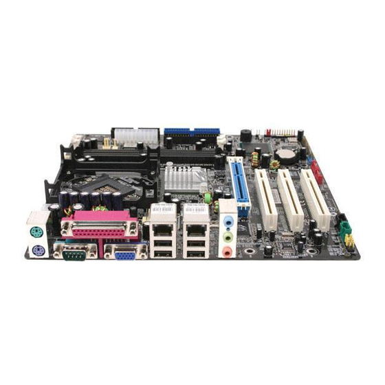
2.1 How does your motherboard look like?...........................................................6
2.2 Specification ...............................................................................................7
2.3 Block Diagram ............................................................................................8
Chapter 3 Hardware Installation ............................................................... 9
3.1 Quick Installation Procedure .........................................................................9
3.2 Installation You Have to Know..................................................................... 10
Installing CPU ...........................................................................................10
Installing CPU Cooler .................................................................................11
Installing CPU and System Fans ..................................................................14
Installing Memory Modules .........................................................................15
Connecting IDE and Floppy Cables ..............................................................16
Connecting Front Panel Cable .....................................................................17
Connecting ATX Power Cables .....................................................................18
3.3 Other Installation for Your Reference ........................................................... 19
Setting CPU Voltage and Frequency .............................................................19
Connecting Serial ATA................................................................................20
Connecting AGP 4X Expansion Slot ..............................................................21
Connecting IrDA........................................................................................22
Dual Gigabit LAN Supported .......................................................................23
Connecting USB2.0....................................................................................24
Connecting 1394 .......................................................................................25
Super 5.1 Channel Audio Effect ...................................................................26
1
Advertisement
Table of Contents

Related Manuals for AOpen i855GMEm-LFS


Summary of Contents for AOpen i855GMEm-LFS
-
Page 1: Table Of Contents
Table of Contents Table of Contents Table of Contents ................... 1 1.1 A Thank-you Note Before You Get Start............4 1.2 Features of This Manual ................5 1.3 Safety Information ..................5 Chapter 2 Introduction to This Motherboard ..........6 2.1 How does your motherboard look like?............6 2.2 Specification ....................7 2.3 Block Diagram ....................8 Chapter 3 Hardware Installation ............... - Page 2 Connecting Front Audio ................27 Connecting CD_IN ..................28 Connecting AUX_IN ...................29 Connecting COM2..................30 Connecting Case Open ................31 Connecting S/PDIF (Sony/Philips Digital Interface) ........32 Colored Coded Back Panel ................33 LED Indication ..................34 3.4 Jumper Settings ..................35 Chapter 4 Special Features and Utilities........... 36 4.1 RAID (Redundant Array of Independent Disks)..........
- Page 3 Exit without Saving ...................58 Load EEPROM Defaults ................58 Save EEPROM Defaults................58 Credits.....................58 5.4 BIOS Upgrade under Windows environment..........59 5.5 Vivid BIOS technology ................61 Chapter 6 Installing Drivers ..............62 6.1 Installing Drivers..................63 6.2 Installing Utilities ..................64 Chapter 7 Troubleshooting..............
-
Page 4: A Thank-You Note Before You Get Start
We regret not informing about any changes in usage standards and other related information. AOpen reserves the right of altering or modifying the content of this manual. In case of any mistakes or incorrect descriptions, which include those on the products, AOpen makes no guarantee or commitments. -
Page 5: Features Of This Manual
1.2 Features of This Manual To help you grab the useful information of this motherboard and aware of certain conditions that you might need to know, you will see the icons below frequently: Note This contains knowledge you should know in process of assembling, or some helpful tips. -
Page 6: Chapter 2 Introduction To This Motherboard
Chapter 2 Introduction to This Motherboard Chapter 2 Introduction to This Motherboard 2.1 How does your motherboard look like? 1. JP28 PS2 KB/Mouse Wakeup Jumper 17. Onboard AC’97 CODEC 2. COM2 Connector 18. Front Audio Connector 3. 4-pin 12V ATX Power Connector 19. -
Page 7: Specification
2.2 Specification Here is the main function of your motherboard. Models i855GMEm-LFS Intel Pentium M (Dothan and Banias) CPU Socket 479 400MHz Chipset Intel 855GME/ICH4-M 200/266/333MHz DDR DIMM x 2 Main Memory DIMM Type : 256/512MB & 1GB Max Memory : 2GB... -
Page 8: Block Diagram
2.3 Block Diagram Socket 479 Intel Pentium M PCI Bus 32-bit PCI Slot x3 400MHz 33/66/100 System Bus IDE Drives x 4 VGA Onboard Intel 855GME AGP bus RealTek Chipset AGP 4X AC97 CODEC AGP 4X Slot DIMM Sockets x2 DDR 333/266/200 RAM Up to 2GB ICH4-M... -
Page 9: Chapter 3 Hardware Installation
Chapter 3 Hardware Installation Chapter 3 Hardware Installation 3.1 Quick Installation Procedure 12. Installing Drivers & 1. Installing CPU Utilities 11. Installing Operating System 2. Installing CPU (such as, Windows Fan & System Fan 10. Loading Default BIOS, Setting CPU 3. -
Page 10: Installation You Have To Know
3.2 Installation You Have to Know Installing CPU This socket supports uFCPGA & uFCBGA package CPU, which is the latest CPU package developed by Intel. Other forms of CPU package are impossible to be fitted in. Unscrew the socket screw counter-clockwise. Locate Pin 1 in the socket and look for a golden arrow on the CPU upper interface. -
Page 11: Installing Cpu Cooler
Installing CPU Cooler This motherboard comes with a special CPU cooler desiged by AOpen, please follow the following steps to install CPU cooler. Please apply thermal paste on the bottom of CPU cooler. Thermal paste Gently put CPU cooler onto the CPU retention module. - Page 12 Install two cooler fixing sticks into CPU retention module. Note: Make sure that the sticks have hooked CPU retention module firmly. Fix ing stick Push the iron plate of cooler fixing stick up a bit. Iron plate...
- Page 13 Then press iron plate downward till you hear a “clip” sound. Note: Mak e sure that the iron plate h ave hooked CPU retention mo dule firmly.
-
Page 14: Installing Cpu And System Fans
Installing CPU and System Fans Plug the CPU fan cable to the 3-pin CPUFAN connector. If you have chassis fan, you can also plug it in SYSFAN1 connector. +12V Sensor SYSFAN1 Connector +12V Sensor CPUFAN Connector Note: Some CPU fans do not have sensor pin so that they cannot support fan monitoring. -
Page 15: Installing Memory Modules
Installing Memory Modules DIMM slots are designed in black which are very easy to recognize. Insert the module straight down to the DIMM slot with both hands and press down firmly until the DIMM module is securely in place. Pin 1 Note: The tabs of the DIMM slot will clip to hold the DIMM in place when the DIMM... -
Page 16: Connecting Ide And Floppy Cables
Connecting IDE and Floppy Cables Connect the 34-pin floppy cable and 40-pin, 80-wire IDE cable to floppy connector and IDE connector. Be careful of the pin1 orientation. Wrong orientation may cause system damage. FDD Connector Secondary Secondary Pin 1 Slave (4th) Master (3rd) Pin 1 Primary... -
Page 17: Connecting Front Panel Cable
Connecting Front Panel Cable Attach the power LED, speaker and reset switch connectors to the corresponding pins. If you enable “Suspend Mode” item in BIOS Setup, the ACPI & Power LED will keep flashing while the system is in suspend mode. Locate the power switch cable from your housing, which is a 2-pin female connector from the housing front panel. -
Page 18: Connecting Atx Power Cables
Connecting ATX Power Cables This motherboard comes with a 20-pin and 4-pin ATX power connector as shown below. Make sure you plug them in the right direction. We strongly recommend you to insert the 4-pin connector before connecting the 20-pin connector. -
Page 19: Other Installation For Your Reference
3.3 Other Installation for Your Reference Setting CPU Voltage and Frequency Setting CPU Core Voltage This motherboard supports Voltage ID (VID) function to detect CPU voltage automatically during power-on. Setting CPU Frequency This motherboard is CPU jumper-less design, you can set CPU frequency through 1MHz stepping CPU Overclocking in the BIOS. -
Page 20: Connecting Serial Ata
Connecting Serial ATA To connect a serial ATA disk, you have to have a 7-pin serial ATA cable. Connect two ends of the serial ATA cable to the serial ATA header on the motherboard and the disk. Like every other traditional disk, you also have to connect a power cable. Please be noted that it is a jumper free implement;... -
Page 21: Connecting Agp 4X Expansion Slot
Connecting AGP 4X Expansion Slot This motherboard provides an AGP 4X slot. The AGP 4X is a bus interface targeted for high-performance 3D graphic, and the data transfer rate could achieve 66MHz x 4bytes x 4 = 1056MB/s. -
Page 22: Connecting Irda
Connecting IrDA The IrDA connector can be configured to support wireless infrared module, with this module and application software such as Laplink or Windows Direct Cable Connection, user can transfer files to or from laptops, notebooks, PDA devices and printers. This connector supports both HPSIR (115.2Kbps, 2 meters) and ASK-IR (56Kbps). -
Page 23: Dual Gigabit Lan Supported
Dual Gigabit LAN Supported On the strength of dual Gigabit LAN controller on board, this motherboard provides 10/100/1000Mbps Ethernet for office and home use. The Ethernet RJ45 connector is located on the top of USB connectors. The right hand side LED indicates link mode;... -
Page 24: Connecting Usb2.0
Connecting USB2.0 This motherboard provides six USB 2.0 ports to connect USB devices such as mouse, keyboard, modem, printer, etc. There are four ports on the back panel. You can use proper cables to connect Front USB connector to USB modules or chassis front panel. -
Page 25: Connecting 1394
Connecting 1394 With IEEE1394 Chip on board (AGERE 1394), having its data transfer rate up to 400Mb/s, this interface can connect to devices that require high data transferring performance such as digital camera, scanner or others IEEE 1394 devices. Please use appropriate cables to connect IEEE1394 devices. -
Page 26: Super 5.1 Channel Audio Effect
Super 5.1 Channel Audio Effect This motherboard comes with a Realtek AC’97 CODEC (ALC655), which supports high quality of 5.1 Channel audio effects, bringing you a brand new audio experience. On the strength of the innovative design of ALC655, you're able to use standard line-jacks for surround audio output without connecting any external module. -
Page 27: Connecting Front Audio
Connecting Front Audio If the housing is designed with an audio port on the front panel, you’ll be able to connect onboard audio to front panel through this connector. By the way, please remove the jumper cap from the Front Audio Connector before you connect the cable. -
Page 28: Connecting Cd_In
Connecting CD_IN This connector is designed to connect CD Audio cable from CDROM or DVD drive to onboard sound. CD-IN Connector... -
Page 29: Connecting Aux_In
Connecting AUX_IN This connector is used to connect MPEG Audio cable from MPEG card to onboard sound. AUX-IN Connector... -
Page 30: Connecting Com2
Connecting COM2 This motherboard provides two serial ports. One of them is on back panel connector, and the other is on the upper of CPU socket. With proper cable, you can connect it to the back panel of chassis. Pin 1 CTS# RTS# DSR#... -
Page 31: Connecting Case Open
Connecting Case Open The “CASE OPEN” header provides chassis intrusion-monitoring function. To make this function work, you have to enable it in the system BIOS, connect this header to a sensor somewhere on the chassis. So, whenever the sensor is triggered by lights or by the opening of the chassis, the system will beep to inform you. -
Page 32: Connecting S/Pdif (Sony/Philips Digital Interface)
Connecting S/PDIF (Sony/Philips Digital Interface) S/PDIF (Sony/Philips Digital Interface) is a newest audio transfer file format, which provides impressive audio quality through optical fiber and allows you to enjoy digital audio instead of analog audio. Through a specific audio cable, you can connect the S/PDIF connector to other end of the S/PDIF audio module, which bears S/PDIF digital output. -
Page 33: Colored Coded Back Panel
Colored Coded Back Panel The onboard I/O devices have PS/2 Keyboard, PS/2 Mouse, RJ-45 LAN Connector, COM1, VGA port, Printer, USB, and AC’97 sound. The view angle of drawing shown here is from the back panel of the housing. SPP/EPP/ECP RJ45 RJ45 PS/2 Mouse... -
Page 34: Led Indication
LED Indication LED indication including Standby LED and BOOT LED are AOpen’s considerate designs that aim at providing you friendly system information. STBY LED will light up when power is provided to the motherboard, giving you a convenient indication check the system power status in circumstances such as power on/off, stand-by mode and RAM power status during Suspend to RAM mode. -
Page 35: Jumper Settings
3.4 Jumper Settings This motherboard provides PS2 keyboard / mouse JP28 Keyboard / Mouse wake-up function. Wakeup Jumper JP28 PS2 KB/Mouse Wakeup Jumper Disable Enable (Default) Normal Clear CMOS (Default) JP14 Clear CMOS Jumper You can clear CMOS to restore system default setting. To clear the CMOS, follow the procedure below. -
Page 36: Chapter 4 Special Features And Utilities
4.1 RAID (Redundant Array of Independent Disks) With the latest Promise PDC20579 implemented, i855GMEm-LFS provides RAID 0 and RAID 1 function for the Serial ATA hard disks. You may use FastBuild Utility provided by Promise to setup your disk array. For more RAID introduction, please visit our website: http://english.aopen.com.tw/tech/techinside/RAID.htm... - Page 37 The main menu of FastBuild Utility: After pressing <CRTL-F>, you will be presented with a screen as shown below. It’s the main menu of FastBiuld utility, you can use this utility to create or delete your disk arrays. Auto Setup: Press 1 to enter Auto Setup. You can choose “Performance” (RAID 0) or “Security”...
- Page 38 View Drive Assignments: Press 2 to enter View Drive Assignments and BIOS will show you the hard drive information by physical array. Define Array: Press 3 to enter Define Array and BIOS will allow you to setup a RAID array by choosing Array No, RAID Mode, and Total Drv. Note : If you are not familiar with FastBuil...
- Page 39 Delete Array: Press 4 to enter Delete Array and BIOS will allow you to delete an existing RAID array. Rebuild Array: Press 5 to enter Rebuild Array and BIOS will allow you to rebuild a crashed RAID array.
-
Page 40: Other Useful Features
4.2 Other Useful Features With excellent design ability of R&D team, AOpen boasts for its various powerful and handy features that come with our product like follows. You are welcomed visit technical website learn more about those features. http://english.aopen.com.tw/tech/techinside... -
Page 41: Chapter 5 Setting Bios
AOpen’s R&D engineering team had optimized most BIOS settings of this motherboard. However, some default settings of BIOS cannot fine-tune those sections that controlled by chipset. Therefore, this chapter is intended to guide you and help you to configure some other settings. -
Page 42: How To Use Phoenix-Award™ Bios Setup Program
5.2 How To Use Phoenix-Award™ BIOS Setup Program Generally, you can use arrow keys to highlight items that you want to choose, press <Enter> key to select, and use <Page Up> and <Page Down> keys to change setting values. You can press <Esc> key to quit Phoenix-Award™ BIOS setup program. -
Page 43: Standard Cmos Features
Standard CMOS Features The "Standard CMOS Setup" sets the basic system parameters such as the date, time, and the hard disk type. Use the arrow keys to highlight an item and <PgUp> or <PgDn> to select the value for each item. Standard CMOS Features >... - Page 44 IDE HDD Auto-Detection: Press “Enter” to auto-detect parameters of HDD IDE Channel 0 Master (Slave): Define the parameters of IDE devices in Channel 0 (Master or Slave). Available options: None: if there is no device, please select “None” for speeding boot up. Auto: enable BIOS to auto-detect parameters of IDE device.
-
Page 45: Advanced Bios Features
Advanced BIOS Features This screen appears when you select the option "Advanced BIOS Features" from the main menu. Advanced BIOS Features > CPU feature Delay Prior to Thermal: Select delay time periods prior to enabling the Thermal Monitor. Available options: 4 Min / 8 Min / 16 Min / 32 Min Thermal Management: Set the function of CPU internal Thermal Management. - Page 46 Advanced BIOS Features > Removable Device Priority Advanced BIOS Features > Hard Disk Boot Priority Advanced BIOS Features > CD-ROM Boot Priority This parameter allows you to specify the system boot up search sequence. Advanced BIOS Features > First Boot Device Advanced BIOS Features >...
-
Page 47: Advanced Chipset Features
Advanced BIOS Features > Bypass Vivid BIOS This item allow user to bypass Vivid BIOS or not when booting up. Advanced Chipset Features The "Advanced Chipset Features" includes settings for the chipset dependent features. These features are related to system performance. Warning: Make sure... - Page 48 Advanced Chipset features > DRAM RAS# Precharge If an insufficient number of cycles are allowed for the RAS to accumulate its charge before DRAM refresh, the refresh may be incomplete and the DRAM may fail to retain data. Fast give faster performance; and Slow gives more stable performance.
-
Page 49: Integrated Peripherals
Integrated Peripherals This submenu appears if you select the option "Integrated Peripherals" from the main menu. This option allows you to configure the I/O features. Integrated peripherals > OnChip IDE Device This parameter allows you to “Enable” or “Disable” the IDE device connected to the primary or secondary IDE connector. - Page 50 USB Controller: This item lets you enable or disable the USB controller. USB 2.0 Controller: This item lets you enable or disable the USB 2.0 controller. USB Keyboard Support: This item lets you enable or disable the USB keyboard driver within the onboard BIOS. The keyboard driver simulates legacy keyboard command and let you use USB keyboard during POST or after boot if you don't have USB driver in the operating system.
- Page 51 Power ON Function: This item is used to select Wake on Keyboard/Mouse mode. Any Key: This function allows you wake up the system by clicking any key. Button Only: Disable Wake on KB/MS function. You can boot up your system by power button only. Keyboard 98: If selecting this option, you can boot up the system by power button and the “Wake”...
-
Page 52: Power Management Setup
ASKIR: This setting allows infrared serial communication at a maximum baud rate of 57.6K baud. RXD, TXD Active: This item is used to select RxD (Receive Data) and TxD (Transmit Data) mode for UART, for instance, IR device, modem, etc. Normally, we suggest you keep the default setting. - Page 53 Power Management > ACPI Suspend Type This function allows you to select suspend types. S1 is Power On Suspend and S3 is Suspend to RAM. Available Options: S1, S3, S1 & S3 Power Management > Soft-off by PWR-BTTN This is a specification of ACPI and supported by hardware. When Delay 4 sec. is selected, the soft power switch on the front panel can be used to control power On, Suspend and Off.
-
Page 54: Pnp/Pci Configurations
Power Management > Date (of Month) Alarm This item is displayed when you enable the Wake On RTC Timer option. Here you can specify what date you want to wake up the system. For Example, setting to 15 will wake up the system on the 15th day of every month. Tip: Setting this item to 0 will wake up the syst em on the specified time (which can be set in... -
Page 55: Silent Bios/Hw Monitor
Silent BIOS/HW Monitor This submenu displays Silent BIOS / HW monitor status and provides some basic control function. Silent BIOS/HW Monitor > CPU Warning Temperature This item is used to specify a CPU warning temperature. When the CPU’s temperature is higher than this predefined value, the CPU’s speed will automatically slow down and there will be a warning from BIOS. -
Page 56: Frequency/Voltage Control
Frequency/Voltage Control This submenu allows you to configure the CPU and memory clock. Frequency/Voltage Control > CPU Bus Frequency his item allows user to overclock the bus frequency of CPU. The range is from 100 to 400. Tip: When you fail to overclock, you could: Clear CMOS (JP14) to restore the default setting. -
Page 57: Load Setup Defaults
Load Setup Defaults The "Load Setup Defaults" option loads optimized settings for optimum system performance. Optimal settings are relatively safer than the Turbo settings. All the product verification, compatibility/reliability test report and manufacture quality control are based on "Load Setup Defaults". We recommend using these settings for normal operation. -
Page 58: Set Password
You may use this item to save your own settings into EEPROM. Then, if the data in CMOS is lost or you forget the previous settings, you may use "Load EEPROM Default" to reload. Credits List of all excellent AOpen’s R&D join the research and development of this motherboard. -
Page 59: Bios Upgrade Under Windows Environment
5.4 BIOS Upgrade under Windows environment With outstanding R&D ability of AOpen, we now bring you a whole new BIOS Flash wizard ---- EzWinFlash. With an eye to convenience for users, EzWinFlash combines the BIOS binary code and flash module together, so the only thing you have to do is just clicking on the utility you downloaded from web and let it help you complete the flash process automatically. - Page 60 STRONGLY RECOMMENDED to close all applications before you start the upgrades. Download the latest version of BIOS package zip file from AOpen official web site. (Ex: http://english.aopen.com.tw/) Unzip the downloaded BIOS package (ex: WSGMAXII102.ZIP) with WinZip (http://www.winzip.com) in Windows environment.
-
Page 61: Vivid Bios Technology
Have you been fed up with the conservative and immutable POST screen? Let’s rule out the tradition idea that POST screen are stiff and frigid, and let AOpen show you the newly developed VividBIOS to experience the lively vivid colorful POST screen! -
Page 62: Chapter 6 Installing Drivers
Click and done. Yes. EzInstall makes installation easy and even foolproof! After putting in the CD, you will be prompted with AOpen welcome page and our branches information. First, click on the install driver ICON at left side for necessary drivers. -
Page 63: Installing Drivers
6.1 Installing Drivers As you may see from the Installing driver page, EzInstall had picked up necessary for your motherboard. All you have to do is just click on the “GO”, and no more steps afterward, of all listed drivers, grey checks indicate necessary drivers; you cannot click them off. -
Page 64: Installing Utilities
6.2 Installing Utilities Installing Utilities is virtually the same as installing drivers. AOpen provides you many friendly and powerful utilities to manage your system. You may find lots of fabulous utilities listed there, and all you have to do is to click on the “GO”, then it will install the utilities to your system right away without complicated steps. -
Page 65: Chapter 7 Troubleshooting
Chapter 7 Troubleshooting Chapter 7 Troubleshooting... -
Page 66: Chapter 8 Technical Support
Gold Member of Club AOpen so as to ensure quality service in the future. In order to maintain the best service to every customer of us, we recommend you to follow the procedures below and seek help from our branches according to the region you buy the product. -
Page 67: Model Name And Bios Version
Gold member of Club AOpen, and to ensure high service quality and priority from AOpen. You will also have a chance to play slot machine game to win prize from AOpen. Please prepare the following information before you start: Model Name, Part Number (P/N), Serial Number (S/N) and Purchase Date. -
Page 68: Technical Support
Technical Support...
Need help?
Do you have a question about the i855GMEm-LFS and is the answer not in the manual?
Questions and answers