
Related Manuals for Zibro Laser FF 30


Summary of Contents for Zibro Laser FF 30
- Page 1 Laser FF 30 MANUEL D’UTILISATION OPERATING INSTRUCTIONS GEBRUIKSAANWIJZING KULLANIM KILAVUZU...
-
Page 2: Operating Instructions
Dear Sir, Madam, Dear Sir, Madam, Congratulations with your purchase of the Zibro, the number one brand among Congratulations with your purchase of the Zibro, the number one brand among movable heaters. You have purchased a first-class quality product, which will movable heaters. - Page 3 SUMMARY Chapter 1: INSTALLATION Chapter 2: OPERATION Chapter 3: ERROR MASSAGES Chapter 4: WARRANTY PROVISIONS...
- Page 4 THE RIGHT FUEL Only use Class C1 paraffin fuel in accordance with BS2869: Part 2, or equivalent. Your Zibro heater has been designed for use with high-quality water-free pure paraffin oil, such as Zibro Extra or Zibro Kristal. Only fuels of this kind will ensure clean and proper burning.
- Page 5 Chapter 1, INSTALLATION 1. Introduction Recommended tool kit This chapter contains all the relevant information, 1. Crosshead screwdriver specifically: 2. Steel tape measure 3. Felt-tip pen or pencil • Installation specifications 4. Cement for exterior use • List of installation tools 5.
- Page 6 Only the standard feed and exhaust system is supplied with the heater. More than 60 cm More than 10 cm More than 30 cm More than 30 cm More than 1.5 m Laser FF 30 Fig. 1-1: Gaps heater/exhaust pipe...
- Page 7 Chapter 1, INSTALLATION Flammable object Flammable object Not less than 60 cm Not less Non-flammable than 45 cm object Not less than 45 cm Not less than 60 cm 45°C Not less than 30 cm Exhaust pipe Not less than 20 cm* Not less than 20 cm* * This clearance has to be present also in case of snowfall, etc.
- Page 8 Back of the heater The center of The center of the flue pipe the flue pipe Laser FF 30 78 mm Fig. 1-3 Template Do not remove any components from the heater. Always contact your dealer if repairs are required.
-
Page 9: Table Of Contents
Standard installation parts The following list of standard installation parts is sup- plied with your heater. It may be necessary to order extra parts from your Zibro dealer if other installation methods are required. Wall hooks (2 set) Pipe holder (1) - Page 10 Chapter 1, INSTALLATION Flexible air hose (1) Hose clip (2) Manual fuel pump (1) Fuel cap cover (1)
- Page 11 Chapter 1, INSTALLATION 1. For the standard installation, use the template sup- Use cellotape or small nails to attach the template to plied to position the hole for the exhaust pipe correctly. the desired position on the wall (see Fig. 4). Tape Fig.
- Page 12 Chapter 1, INSTALLATION 3. Install the inner flue pipe. a. For wall thickness 230~320mm. From inside the room, insert the inner flue pipe through the hole. Make sure the arrow on the inner flue pipe is pointing up. Secure the inner flue pipe to the wall with the three wood screws. (See Fig. 7) Inside Outside inside...
- Page 13 Chapter 1, INSTALLATION c. From outside, insert the outer flue pipe through the hole. Secure the outer flue pipe to the wall by turning it clockwise. This locks the two halves together (See Fig. 9). IMPORTANT: Make sure the arrow on the outer flue pipe frange is pointing up. Make sure to secure the outer flue pipe well.
-
Page 14: Pipe Lock
Chapter 1, INSTALLATION 5. Move the heater into position. Attach the right-angled attach the right-angled exhaust pipe bend to the inlet. exhaust pipe bend to the outlet of the exhaust pipe and Make sure all connections are tight (See Fig. 11). Outlet Right-angled exhaust bend Inlet... -
Page 15: Right-Angled Air Hose
Chapter 1, INSTALLATION CHECKLIST • Check whether the heater has been connected to a suitable socket. • Ensure that the fuel is free of water or other contaminants. • Check outside the building in order to ascertain that there is no fuel or obstructions to the free circulation of air in the area immediately adjacent to the exhaust pipe. - Page 16 This chapter provides all the information required for the operation of the Laser heater system. All specified operating procedures must be carried out in the order in which they are described. 2. Laser FF 30 heater specifications Medium High Heat yield (W)
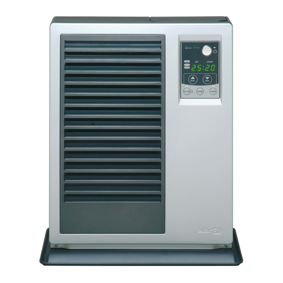
- Page 17 Chapter 2, OPERATION 3. Operating elements and lights 1. ON/OFF button 3. Information display 2. Adjustment buttons 2. Adjustment buttons (time and temperature) (time and temperature) 4. Save button 4. Save button 5. Timer button 5. Timer button 6. Childproof lock button Fig.
- Page 18 Chapter 2, OPERATION 4. Prior to use [4] Lock the switch button on top of the pump (turn Step 1: Filling fuel clockwise). • Do not fill the removable tank in the living [5] Squeeze the pump a few times, until fuel starts room, but in a more suitable place (there flowing into the removable tank.
- Page 19 Chapter 2, OPERATION function (the CLOCK light and the information perature using the button on the right ( min.) to set the display will start blinking). Next, set the hours using temperature to a higher setting and the button on the the button on the left ( hour) and the minutes left ( hour) to lower the temperature.
- Page 20 Chapter 2, OPERATION 6. Timer operation 8. Childproof lock The timer allows you to switch on the heater automati- The childproof lock can be used to prevent children cally at a preset time. accidentally changing the heater settings. When the In order to switch on the timer, the correct time must heater is burning and the childproof lock is on, the have been set and the heater should be off.
- Page 21 Also disconnect the plug from the mains. Circulation of air in the room does not start immediately Your Zibro needs hardly any maintenance. It is, however, when the heater is lit. important that you clean the louvers, grilles and circulation To prevent unpleasant cold draughts, the ventilator only fan cover on the back of the heater weekly.
-
Page 22: Error Messages
Chapter 3, ERROR MESSAGES ERROR CODE INFORMATION WHAT TO DO Power interrupted. Re-ignite the heater Ignition safety feature is activated. Contact your dealer Extinguished during operation. Contact your dealer Blower motor malfunction. Contact your dealer E-12 Overheating safety feature is activated. Clean the air filter and remove dust. - Page 23 Chapter 4, WARRANTY PROVISIONS Your heater comes with a 24-months warranty starting on Waste electrical products should not be dis- the date of purchase. Within this period all defects in posed with household waste. Please recycle material or workmanship will be repaired without any where facilities exist.
- Page 24 +44 1606 837787 tel: +43 7434 44867 fax: +44 1606 837757 fax: +43 7434 44868 email: sales@scottmail.co.uk email: pvgaustria@zibro.com > ITALIA e BELGIË PVG Italy SRL PVG Belgium NV/SA Via Niccolò Copernico 5 Industrielaan 55 50051 CASTELFIORENTINO (FI) 2900 SCHOTEN tel:...
Need help?
Do you have a question about the Laser FF 30 and is the answer not in the manual?
Questions and answers