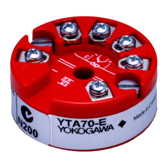
Summary of Contents for YOKOGAWA vigilantplant YTA70
- Page 1 User’s YTA70 Manual Temperature Transmitter IM 01C50C03-01E IM 01C50C03-01E 6th Edition...
-
Page 2: Table Of Contents
7.2 FM Intrinsically safe model ..........7 HART COMMUNICATION .............8 8.1 Connection and Requirements ..........8 8.2 Parameters ................9 ◆ REVISION RECORD FD No. IM 01C50C03 -01E 6th Edition: Feb. 2007 (YK) IM 1C50T1-01E All Rights Reserved, Copyright © 1999, Yokogawa Electric Corporation... -
Page 3: Safety Instructions
SAFETY INSTRUCTIONS Ex/I.S. installation: • For correct use and installation the manufacturer’s manual must be fol- lowed. When programming the Transmitter by PC and communication interface or a HART® terminal the intrinsically safe data shall be observed. • The designation galvanic isolation between the transducer input and the loop supply indicates signal isolation only. -
Page 4: Model And Suffix Codes
The YTA70 is a head mount type of temperature transmitter that accepts thermocouple or RTD input and converts it to a 4 to 20 mA DC signal for transmission. The YTA70 specifies HART communication protocol for re- mote configuration. It is imperative that usres observe the instructions in this manual to ensure the protection and safety of operators. -
Page 5: Handling Precautions
(5) Yokogawa will not be liable for malfunctions or damage resulting from any modification made to this instrument by the customer. - Page 6 Cold Junction Compensation Accuracy(For T/C only) ±1°C(±1.8°F) Ambient Temperature Effects (per 10 C Change) ° For E, J, K, L, N, T and U thermocouple inputs: ±0.05% of span or ±0.25°C, whichever is greater For R, S, B, W3 and W5 thermocouple inputs: ±0.05% of span or ±1°C, whichever is greater For Pt100 and Ni100 RTD inputs: ±0.05% of span or ±0.05°C, whichever is greater...
-
Page 7: Block Diagram
Supply Voltage 8 to 35 V DC 8 to 30 V DC for Intrinsically safe type 13.8 to 35 V DC for digital communication Load Resistance Limitation: 0 to (E–8)/0.0236 [Ω], where E is power supply voltage. Isolation Input/output isolated to 1500 V AC. Mounting DIN form B head mounting Terminals... -
Page 8: Safety Approvals
■ WIRING DIAGRAM SUPPLY SUPPLY SUPPLY SUPPLY (–) (–) (–) (–) (–) T/C or Two-wire Three-wire Four-wire DC milivolts RTD or ohm RTD or ohm RTD or ohm F03E.EPS ■ DIMENSIONS Unit : mm (approx. inch) 33 (1.30) 20.2 (0.80) F02E.EPS 7. -
Page 9: Fm Intrinsically Safe Model
Intrinsically safety rating(maximum value) Output/Power supply : Ui=28 V, Ii=120 mA, Pi=0.84 W, Ci<1 nF, Li<10 µH Sensor : Uo=9.6 V, Io=28 mA, Po=67 mW, Co<3.5 µF, Lo<35 mH Applicable in Zone 0, 1, or 2 Maximum Ambient Temperature For T1-T4: 85°C, For T5/T6: 60°C 7.2 FM Intrinsically safe model (/DS2) Applicable Standard: FM 3600, FM 3610, FM 3611, FM 3810 Installation diagram... -
Page 10: Hart Communication
8. HART COMMUNICATION 8.1 Connection and Requirements A standard HART communicator can be used for programming the YTA70. The HART communicator must be loaded with the appropriate DDL driver for YTA70. Minimum loop resistance is 250Ω. If the receiving equipment has a lower resistance, a serial resistor must be inserted to communicate with the HART communicator. -
Page 11: Parameters
8.2 Parameters (Device setup) (Process Variables) 1.PV 1.Process Variable 2.Electr 3.Snsr1 4.PV AO (Status) 5.PV % rnge 1.Sensor errors (Diag/Service) 2.ADC errors 2.Diag/ 1.Status 3.Misc. errors Service (Calibration) (Range values) 2.Loop test 1.PV LRV 1.Range values 2.PV URV 2.D/A trim 3.PV unit 3.Calibration 3.Scaled... - Page 12 Parameters List(1/3) Initial HART Item Selection/ Setting Range Setting Communicator Measured variables in engineering — Process Process Variable unit. Variable Terminal temperature — Electr Output — Output value in mA PV AO value PV % rnge Output value with respect to the —...
- Page 13 Parameters List (2/3) Initial HART Item Selection/ Setting Range Setting Communicator Output AO 0%(100%) Output value for 0%(100% ) in mA. 4 (0%) Analog Condition Output 20 ( 100% range NAMUR Output lower(upper) limit in mA. AO lo(up) lim NAMUR, or 3.8 to 23mA Enter or select the output value Sensor Error NAMUR...
- Page 14 Parameters list (3/3) Initial HART Item Selection/ Setting Range Setting Communicator Yokogawa Device information Manufacturer identification code Manufacturer YTA70-E Model name Model Tag number, up to 8 alpha- — numerical characters. Descriptor Text which can be used by user in —...
-
Page 15: Revision Record
◆ Revision Record ● Manual No. : IM 01C50C03-01E ● Title YTA70 Temperature Transmitter Edition Date Page Revised item Mar. 1999 — New Publication Add code "/DS1" in the table Jun. 1999 Add "7.2 FM intrinsically safe model" Add "note 2" . Revise accuracy &... - Page 16 Branch Sales Offices / Wien (Austria), Zaventem (Belgium), Ratingen (Germany), Madrid (Spain), Runcorn (United Kingdom), Milano (Italy), Velizy Villacoublay (France), Roodeport (Republic of South Africa), Budapest (Hungary), Stockholm (Sweden) YOKOGAWA AMERICA DO SUL Ltda. Head Office Praca Acapulco, 31 - Santo Amaro. Sao Paulo/SP - BRAZIL Phone : 55-11-5681-2400 Fax : 55-11-5681-4434 YOKOGAWA ELECTRIC ASIA PTE.


Need help?
Do you have a question about the vigilantplant YTA70 and is the answer not in the manual?
Questions and answers