Table of Contents
Advertisement
Advertisement
Table of Contents

Related Manuals for Lowrance Link-5 VHF


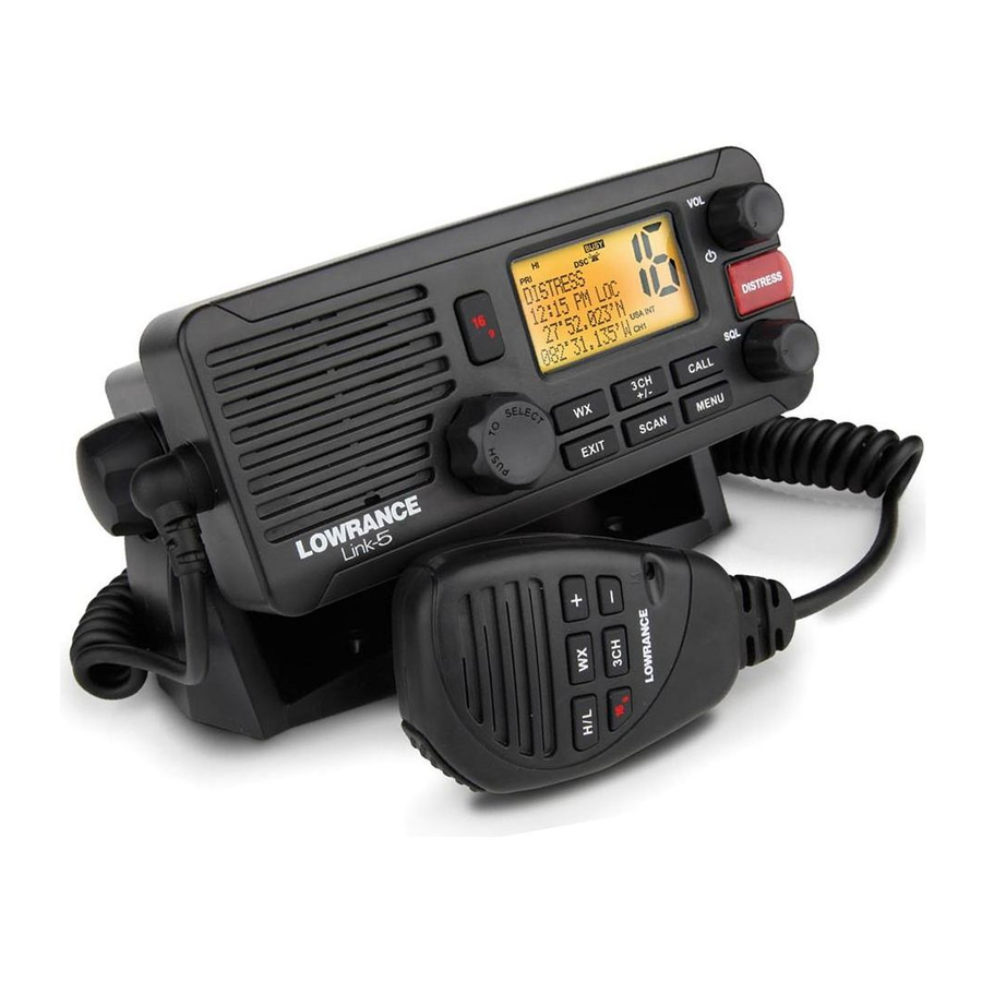
Summary of Contents for Lowrance Link-5 VHF
- Page 1 Link-5 VHF User Guide ENGLISH lowrance.com...
-
Page 2: Important Safety Information
Any unauthorized commercial distribution of this manual is strictly prohibited. Lowrance Electronics may find it necessary to change or end our policies, regulations, and special offers at any time. We reserve the right to do so without notice. All features and specifications subject to change without notice. -
Page 3: Table Of Contents
Section 1 - General Information ...............6 1-1 Features ..............................6 1-2 Customizing your Lowrance VHF Radio ..................7 1-3 How to Display and Navigate Menus ..................7 1-4 How to Enter Alphanumeric Data ....................7 1-5 LCD Symbols and Meanings ......................7 1-6 Basic Operation and Key Functions .....................9 Section 2 - The Radio Menu (MENU) ..............13... - Page 4 5-3-1 Receiving an All Ships Call (ALL SHIPS) ....................38 5-3-2 Receiving an Individual Call (INDIV) ....................38 5-3-3 Receiving a Group Call (GROUP) ......................39 5-3-4 Receiving a Geographic Call (GEOGRAPH) ..................40 5-3-5 Receiving a Polled Position Call (POSITION) .................40 Lowrance - Link-5 Operation and Installation Instructions...
- Page 5 Special Notes on EU International Channel Usage ................63 D-2 Inland Waterways Country Specific table - ATIS ON ............64 D-3 Special Channels ........................67 Appendix E - MMSI, FCC and License Information ..........68 FCC Compliance .................................68 Lowrance - Link-5 Operation and Installation Instructions...
-
Page 6: Section 1 - General Information
Section 1 - General Information 1-1 Features Congratulations on your purchase of this Lowrance Link-5 marine band VHF radio. Your Link-5 provides the following useful features: • Prominent channel display • Adjustable contrast settings for the LCD • Adjustable keypad backlighting for easy night-time use • Waterproof and submersible to comply with JIS-7... -
Page 7: Customizing Your Lowrance Vhf Radio
If you make an error, press - until < is displayed, then press ENT to backup and correct the entry. 1-5 LCD Symbols and Meanings Link-5 LCD showing all segments: Typical Link-5 startup screen: LINK5 AUS/NZ VER:V1.999 DSC IS ON ID:111222333 Lowrance - Link-5 Operation and Installation Instructions... - Page 8 Channel 16 is set as the Priority channel . It is also set as favourite channel 1 . DSC functionality is enabled. There is an incoming DSC call so the receiver is busy . Lowrance - Link-5 Operation and Installation Instructions...
-
Page 9: Basic Operation And Key Functions
1-6 Basic Operation and Key Functions All possible keys and their functions are listed here. Note that some of the keys may not be available depending on your Lowrance VHF radio model. 6 Key handset Link-5 base station radio Key:... - Page 10 CH1 location. Repeat the procedure to store two more favourite channels in the CH2 and CH3 locations respectively. If you try and add another favourite channel it will overwrite the existing CH3. CH1 Lowrance - Link-5 Operation and Installation Instructions...
-
Page 11: Channel Select
Press + or - to step through the available channels one at a time, or hold down to scroll rapidly through all the available channels. See Appendix C for a complete listing of channel charts. Lowrance - Link-5 Operation and Installation Instructions... - Page 12 H/L and PTT at the same time. See Appendix C for a complete listing of channel charts. PAUSE INFO RESEND QUIT ACCEPT/OPT/ACK/ENT DISTR CANCEL Close-up of the Link-5 base station radio, showing the keys Lowrance - Link-5 Operation and Installation Instructions...
-
Page 13: Section 2 - The Radio Menu (Menu)
Turn the GPS Simulator on/off. GPS SIM See Section 2-6. Reset factory settings. RESET See Section 2-7. * Model dependant Sections 1-3 and 1-4 explain how to navigate around the menu and enter, save and change data. Lowrance - Link-5 Operation and Installation Instructions... -
Page 14: Maintain Your Buddy List (Buddy List)
When you are finished, press ENT (repeatedly if necessary) to display the next screen. Press ENT to store the changes. The buddy list is displayed again. If more changes are required, repeat Steps 2 through 6. Otherwise, press EXIT to cancel. Lowrance - Link-5 Operation and Installation Instructions... -
Page 15: Delete An Entry
Use BACKLIGHT to set the backlight levels for the LCD, keypad and MENU SELECT microphone keypad to a comfortable level. LOCAL/DIST▲ ►BACKLIGHT Use CONTRAST to set the contrast level for the LCD. ▼ CONTRAST Lowrance - Link-5 Operation and Installation Instructions... -
Page 16: Set The Backlighting Level
The vessel’s latitude and longitude are shown on the screen, with the UTC time. The prefix M indicates a manual entry. The manual entries are cancelled if a real GPS position is received. Lowrance - Link-5 Operation and Installation Instructions... -
Page 17: Local Time (Time Offset)
2-5-3 Time Format Options (TIME FORMAT) Time can be shown in 12 or 24 hour format. SETTING GPS/DATA TIME FORMAT TIME OFFSET ►12 Hr MANUAL ►TIME FORMAT ►SETTING 24 Hr TIME DISPL▼ 07:15AM LOC Lowrance - Link-5 Operation and Installation Instructions... -
Page 18: Time Display Options (Time Display)
In this example, ON has ►COG/SOG ▼ been selected and the screen shows the bearing and speed. If COG/SOG is set ON (on), the time is not displayed on the screen (see section 2-5-4). Lowrance - Link-5 Operation and Installation Instructions... -
Page 19: Gps Alert Options (Alert)
MENU SELECT RESET RADIO RADIO SETU▲ ARE YOU SURE ►YES GPS SIM ►RESET Select RESET. The radio asks for confirmation. Select YES to reset the radio and return to the menu. Lowrance - Link-5 Operation and Installation Instructions... -
Page 20: Section 3 - Radio Setup Menu (Radio Setup)
Toggle between USA, International or Canadian channel banks. The selected channel bank is displayed on the LCD along with the last used channel. All the channel charts are shown in Appendix C. RADIO SETUP ►UIC ►USA CH NAME INT’L RING VOLUM▼ CANADA Lowrance - Link-5 Operation and Installation Instructions... -
Page 21: Channel Names (Ch Name)
3-5 Internal Speaker Connections (INT SPEAKER) Switch the radio’s internal speaker ON (on) or OFF (off ). The external speaker is always ON (on) if a speaker is plugged into the external speaker jack. Lowrance - Link-5 Operation and Installation Instructions... -
Page 22: Set The Priority Channel (Watch Mode)
The COM Port uses 4800 baud rate and can receive the following GPS data sentence: RMC, GGA, GLL, GNS. Additionally, this radio will output the following NMEA DSC data: DSC (for DSC call), DSE ( for enhanced position). Lowrance - Link-5 Operation and Installation Instructions... -
Page 23: Section 4 - Dsc Setup Menu (Dsc Setup)
4-2-1 Enter your MMSI You can display and read your user MMSI at any time, but you get only one opportunity to enter your user MMSI. Contact Lowrance if you need to change your MMSI after initial input. USER MMSI... -
Page 24: View Your Mmsi
Enter the group MMSI. Note that the first number is always 0. Press ENT. The group name and group MMSI are shown in a confirmation screen. Press ENT to store the details and return to the GROUP SETUP screen. Lowrance - Link-5 Operation and Installation Instructions... -
Page 25: Edit Group Name Details
DSC SETUP ►MANUAL Select AUTO for an automatic response, USER MMSI AUTO GROUP SETUP or MANUAL for a manual response. ►INDIV REPL▼ Press ENT to confirm your choice and return to the menu. Lowrance - Link-5 Operation and Installation Instructions... -
Page 26: Atis Mmsi & Atis Functionality
ATIS MMSI and return to the menu. 4-5-2 View your ATIS MMSI You can view your stored ATIS MMSI at anytime by selecting ATIS MMSI in the main menu, DSC SETUP. Lowrance - Link-5 Operation and Installation Instructions... -
Page 27: Enable Atis Functionality (Atis Func)
You can set the radio to respond to an LL polling request in one of three ways: AUTO automatically replies to any incoming LL polling requests from any of your buddies. MANUAL choose to manually reply to any incoming buddy polling requests. ignores all incoming buddy LL polling requests. Lowrance - Link-5 Operation and Installation Instructions... -
Page 28: Automatic Channel Switching (Auto Switch)
DSC SETUP AUTO SWITCH ▲ ►ON DSC FUNC LL REPLY ►AUTO SWITC▼ Select DSC SETUP, then AUTO SWITCH. Select ON (on) to enable automatic channel switching. Select OFF (off) to disable automatic channel switching. Lowrance - Link-5 Operation and Installation Instructions... -
Page 29: Dsc Test Reply (Test Reply)
►NON AUTO ►10 MINS TEST REPLY ►TIMEOUT 15 MINS In this example, 10 MINS has been selected, meaning the radio will exit any non-automated procedure after a period of 10 minutes of non-activity. Lowrance - Link-5 Operation and Installation Instructions... -
Page 30: Section 5 - Sending And Receiving Dsc Calls
Request the LL position of a buddy. LL REQUEST See Section 5-2-10. Make a DSC TEST call. DSC TEST See Section 5-2-11. Show the programmed MMSI and GPS information MMSI/GPS See Section 5-2-12. Lowrance - Link-5 Operation and Installation Instructions... -
Page 31: Make A Routine Call (Individual)
The radio then waits for an acknowledgement and displays the elapsed time since the call was sent. If the call is acknowledged (ACK), press PTT to talk. If there is no reply, retry making the call. See Section 5-2-2. Lowrance - Link-5 Operation and Installation Instructions... -
Page 32: Retrying A Routine Call
CHANGE CHAN to acknowledge and request a channel change UNABLE ACK* respond to the call with unable to use the requested channel (* Note: this option is not available with ROUTINE calls) Or press QUIT (EXIT) to return to standby. Lowrance - Link-5 Operation and Installation Instructions... -
Page 33: Recall The Most Recent Incoming Call (Last Call)
Select one of the following call priorities: SAFETY to send safety information to all other vessels in range URGENCY for use when a serious situation or problem arises that could lead to a distress situation Lowrance - Link-5 Operation and Installation Instructions... -
Page 34: Call Using The Call Log (Call Log)
YES to confirm. INFO to display more information about the station, such as the location and name or MMSI of the vessel in Distress and the nature of the emergency (if specified). Lowrance - Link-5 Operation and Installation Instructions... -
Page 35: Call Using The Sent Call Log (Sent Call)
The working channel name is displayed while the radio waits for an acknowledgement from your buddy. If there is no reply after 30 seconds the radio asks if you want to retry. Continue as explained in Section 5-2-2. Lowrance - Link-5 Operation and Installation Instructions... -
Page 36: Make A Dsc Test Call (Dsc Test)
The radio will automatically acknowledge the call if TEST REPLY is set to AUTO (See sec- tion 4-9) and after a TIMEOUT period set for AUTO REPLY. (See section 4-10) Scroll to view further information (if available), or press EXIT to cancel. Lowrance - Link-5 Operation and Installation Instructions... -
Page 37: Receiving Dsc Calls
Routine priority only (see Section 5-3-4) POLLED POSITION Routine or Safety priority (see Section 5-3-5) DSC TEST CALL DSC Test Call (see Section 5-2-11) In addition to the audible alert, the telephone icon will flash on the screen. Lowrance - Link-5 Operation and Installation Instructions... -
Page 38: Receiving An All Ships Call (All Ships)
INDIV calls are almost always Routine priority. If the radio recognises the user MMSI as one of your buddies, the buddy’s name is displayed in place of the user MMSI. Lowrance - Link-5 Operation and Installation Instructions... -
Page 39: Receiving A Group Call (Group)
AUTO SWITCH CH13 IN 10S 10:12 UTC information screens are CH13 IN 10S 10:12 UTC ENT–> ACCEPT available by rotating the 10:12 UTC ENT–> ACCEPT KEY->SILENCE CH knob. ▲▼ ▲▼ ▲▼ 00:04 00:05 00:06 Lowrance - Link-5 Operation and Installation Instructions... -
Page 40: Receiving A Geographic Call (Geograph)
If enhanced LL position information is available from your buddy, this is shown on the screen until the screen display changes. POSITION REPLY FROM 12’23.456’N REPLY FROM 123’23.789’E 12’23.456’N 12'23.456'N 123'23.789’E KEY->SILENCE ▼ ▲▼ ▲▼ ▲▼ 00:12 00:22 00:28 00:25 Lowrance - Link-5 Operation and Installation Instructions... -
Page 41: Section 6 - Distress Calls
(Over Board) Hold down the DISTRESS key for about 3 seconds, until you see the distress call sending message (DISTRESS CALL SENDING) on the screen. The whole display starts to flash and beep loudly. Lowrance - Link-5 Operation and Installation Instructions... - Page 42 The following information (if available) is contained in the DIstress Call: - Nature Of Distress (if available) - Position information. The latest GPS or manual input position is held for 23.5 hours, or until the power is turned OFF. Lowrance - Link-5 Operation and Installation Instructions...
-
Page 43: Receiving A Distress Call (Distress!)
900000000 123456789 FLOODING 900000000 82’50.178N ▼ ▲▼ ▲▼ ▲▼ 00:01 00:02 00:03 00:04 Try to make voice contact with the calling vessel. Maintain a listening watch on CH16 and standby to lend assistance Lowrance - Link-5 Operation and Installation Instructions... -
Page 44: Distress Relay Individual (Indiv Distr Relay)
US only models: ACT (ENT) key is pressed, or MANUAL / AUTO ACK (depending on INDIV REPLY setting): INDIV DISTR FLOODING KEY–>SILENCE AUTO CHANGED RELAY FROM 123000000 KEY–>SILENCE ENT–> ACK 900000000 55’29.975’N EXIT–> ESC ENT–> ACK ▼ ▲▼ ▲ ▲ 00:00 00:03 00:07 00:07 Lowrance - Link-5 Operation and Installation Instructions... -
Page 45: Section 7 - Installation
Section 7 - Installation This Lowrance radio is designed to generate a digital maritime distress call to facilitate search and rescue. To be effective as a safety device, this radio must be used only within the geo- graphic range of a shore-based VHF marine Channel 70 distress and safety watch system. The geographic range may vary but under normal conditions is approximately 20 nautical miles. -
Page 46: Checklist
The following items should be supplied in the box. Check before starting the installation and contact your dealer if an item is missing. Note: An antenna is not provided. Consult your Lowrance dealer for advice if necessary. Mounting gimbal for the VHF radio 12. -
Page 47: Gimbal Installation
Re-position the radio then tighten the mounting knobs again. Recessed Installation Tape the installation template onto the chosen location site. Cut out the area marked by the solid dark line. (The dashed line indicates the total area Lowrance - Link-5 Operation and Installation Instructions... -
Page 48: Install The Microphone Bulkhead Mount
Use a short length Philips screwdriver and the set of two flat screws, spring washers, plain washers, and nuts to secure the microphone bulkhead mount at the location site. Hang the microphone on its mount. Lowrance - Link-5 Operation and Installation Instructions... -
Page 49: Fix The Dsc Label
ANT. A radio antenna is not supplied. A suitable radio antenna must be mounted and connected before operating this radio. Consult your dealer for advice if necessary. GND. A ground connection is not usually required. Lowrance - Link-5 Operation and Installation Instructions... -
Page 50: Set Up The Radio
DSC (Digital Select Calling). If you don’t have a user MMSI contact the appropriate authorities in your country. If you’re unsure who to contact, consult your Lowrance dealer. • A Group MMSI begins with 0 followed by 8 numeric digits (0xxxxxxxx) •... -
Page 51: The Completed Installation
Link-5 Base unit with speaker microphone CAUTION Under extreme operating conditions, the temperature of the rear heat-sink on this radio may exceed normal surface temperatures. Caution is advised to prevent possible skin burns. Lowrance - Link-5 Operation and Installation Instructions... -
Page 52: Appendix A - Technical Specifications
Yes, CLASS-D (Global - separate CH70 receiver built in) GPS/NMEA input: GPS data sentences can be received: RMC, GGA, GLL, GNS NMEA output: NMEA output sentences: DSC ( for DSC call), DSE (for enhanced position). Lowrance - Link-5 Operation and Installation Instructions... - Page 53 Residual noise level: more than -40 db unsquelched Audio output power: 2 W (with 8 ohm at 10% distortion) 4 W with 4 ohm external speaker Note: Specifications are subject to change without notice. Lowrance - Link-5 Operation and Installation Instructions...
-
Page 54: Appendix B - Troubleshooting
Check the polarity of the GPS cable. c. Check the baud rate setting of the GPS if applicable. The baud rate setting should be 4800 and parity should be set to NONE. Lowrance - Link-5 Operation and Installation Instructions... -
Page 55: Appendix C - Us & Row Vhf Marine Channel Charts
Public Correspondence TELEPHONE 157.250 161.850 Public Correspondence TELEPHONE 157.300 161.900 Public Correspondence TELEPHONE 157.350 161.950 Public Correspondence TELEPHONE 157.400 162.000 Public Correspondence TELEPHONE 156.025 160.625 Public Correspondence TELEPHONE 156.075 160.675 Port Operations PORT OPS Lowrance - Link-5 Operation and Installation Instructions... -
Page 56: Special Notes On International Channel Usage
Select the INTERNATIONAL channel bank for use in Australia, New Zealand and other Asia Pacific regions, and all other regions where otherwise not specified. KEY: S = Simplex operating channel; D = Duplex operating channel. Lowrance - Link-5 Operation and Installation Instructions... -
Page 57: Usa Channel Chart
Port Operations, VTS in Selected Areas PORT OPS/VTS U.S. Government, Canadian Commercial 156.225 156.225 UNAUTHORIZED Fishing 156.275 156.275 Port Operations PORT OPS 156.325 156.325 Port Operations PORT OPS Commercial, bridge-to-bridge, 1W with 156.375 156.375 BRIDGE COM Power-up Lowrance - Link-5 Operation and Installation Instructions... -
Page 58: Special Notes On Usa Channel Usage
Channel 70 is designated for use exclusively for Digital Selective Calling (DSC), such as Distress, Safety, and Ship Calls. No voice communication is allowed on CH70. This channel is only available on DSC enabled radios. KEY: S = Simplex operating channel; D = Duplex operating channel. Lowrance - Link-5 Operation and Installation Instructions... -
Page 59: Canada Channel Chart
TELEPHONE 157.350 161.950 Public Correspondence TELEPHONE 157.400 162.000 Public Correspondence TELEPHONE 162.000 Public Correspondence ------ ------ TELEPHONE RX only 156.025 160.625 Public Correspondence TELEPHONE 156.075 156.075 U.S. Government, Canadian Coast Guard Yes UNAUTHORIZED Lowrance - Link-5 Operation and Installation Instructions... -
Page 60: Special Notes On Canada Channel Usage
Lightly shaded simplex channels 21A, 23A, 61A, 64A, 81A, 82A, and 83A cannot be lawfully used in Canada waters unless special authorization is obtained from the Canadian Coast Guard. Not for use by the general public. Lowrance - Link-5 Operation and Installation Instructions... -
Page 61: Us & Canada Weather Channels
NOAA Weather Channel NOAA WX RX only WX08 161.650 CANADIAN Weather Channel CANADA WX RX only WX09 161.775 CANADIAN Weather Channel CANADA WX RX only WX10 163.275 NOAA Weather Channel NOAA WX RX only Lowrance - Link-5 Operation and Installation Instructions... -
Page 62: Appendix D - Eu Vhf Marine Channel Charts
Public Correspondence, Port Op PHONE-PORTOP 157.350 161.950 Public Correspondence, Port Op PHONE-PORTOP 157.400 162.000 Public Correspondence, Port Op PHONE-PORTOP 156.025 160.625 Public Correspondence, Port Op PHONE-PORTOP 156.075 160.675 Public Correspondence, Port Op PHONE-PORTOP Lowrance - Link-5 Operation and Installation Instructions... -
Page 63: Special Notes On Eu International Channel Usage
Distress, Safety, and Ship Calls. No voice communication is allowed on CH70. This channel is only available on DSC enabled radios. Maybe Duplex in some regions KEY: S = Simplex operating channel; D = Duplex operating channel. Lowrance - Link-5 Operation and Installation Instructions... -
Page 64: Inland Waterways Country Specific Table - Atis On
156.55 156.55 156.575 156.575 156.6 156.6 a) r) 156.625 156.625 156.65 156.65 f) g) 156.675 156.675 156.7 156.7 156.725 156.725 156.75 156.75 156.775 156.775 156.8 156.8 j) d) o) 156.825 156.825 156.85 156.85 Lowrance - Link-5 Operation and Installation Instructions... - Page 65 74 and 86), Ukraine and the Federal Republic of Yugosla via. The Administra tions concerned should make any possible attempt to make these fre quencies channels as soon as possible available for the radiotelephone service on Inland Waterways and/or the required service catego ry. Lowrance - Link-5 Operation and Installation Instructions...
- Page 66 After permission of the competent authority, this channel may be used only for spe cial events on a temporary basis. In the Czech Republic this channel is used for service category nautical information. In the Czech Republic this channel is used for service category ship-to-port authorities. Lowrance - Link-5 Operation and Installation Instructions...
-
Page 67: Special Channels
FI - Finland LU - Luxembourg CH - Switzerland FR - France MT - Malta TR - Turkey DE - Germany NL - Netherlands UK - United Kingdom GR - Greece NO - Norway Lowrance - Link-5 Operation and Installation Instructions... -
Page 68: Appendix E - Mmsi, Fcc And License Information
Depending upon your location, you may need a radio station license for this radio. You may also need an individual operator’s license. Lowrance recommends that you check the requirements of your national radio communications authorities before operating DSC functions. To enable the DSC functions in this radio: • Enter your valid MMSI: MENU >... - Page 69 Notes: Lowrance - Link-5 Operation and Installation Instructions...
- Page 72 1177...
Need help?
Do you have a question about the Link-5 VHF and is the answer not in the manual?
Questions and answers