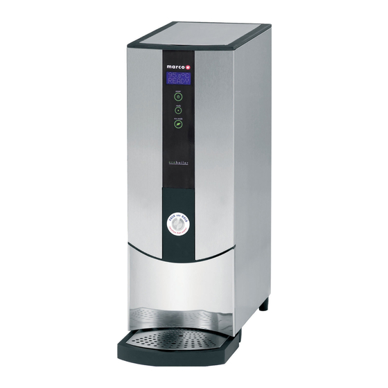
Marco ECOBOILER ECOSMART PB10 Instructions Manual
Hide thumbs
Also See for ECOBOILER ECOSMART PB10:
- Service manual (19 pages) ,
- Instructions manual (12 pages)
Table of Contents
Advertisement
Quick Links
Marco Beverage Systems Ltd.
INSTRUCTIONS FOR MODELS
ECOBOILER ECOSMART PB10
Water pressure : 5 - 50 psi (min.-max.)35 - 345 kPa (min.-max.)
Marco Beverage Systems Limited.
63d Heather Road,
Sandyford Industrial Estate,
Dublin 18.
Ireland Tel: +353 (0)1 295 2674
Ireland Fax: +353 (0)1 295 3715
email: sales@marco.ie
www.marco.ie
(P/N: 1000677, 1000678)
MARCO is an
ISO9001:2000
Registered
Company.
Marco Beverage Systems Limited.
Shire House, Strixton Manor,
Strixton, Wellingborough, Northants,
NN29 7PA
UK Tel: +44 (0)2072 744 577
UK Fax: +44 (0)2079 788 141
email: sales@marco-bev.co.uk
www.marco-bev.co.uk
Advertisement
Table of Contents

Summary of Contents for Marco ECOBOILER ECOSMART PB10
- Page 1 Marco Beverage Systems Ltd. INSTRUCTIONS FOR MODELS ECOBOILER ECOSMART PB10 (P/N: 1000677, 1000678) MARCO is an ISO9001:2000 Registered Company. Water pressure : 5 - 50 psi (min.-max.)35 - 345 kPa (min.-max.) Marco Beverage Systems Limited. Marco Beverage Systems Limited. 63d Heather Road, Shire House, Strixton Manor, Sandyford Industrial Estate, Strixton, Wellingborough, Northants,...
-
Page 2: Installation Details
SAFETY: • This appliance must be earthed. If the moulded plug supplied is not used then ensure that the green/yellow cable is connected to a suitable earth. • Risk of flooding. The hose supplied with this unit is non-toxic food quality tested to 190psi. However, a hose is not a permanent connection. - Page 3 • The boiler is now ready for use – the display will show the Water Temperature and the status “ READY”. • The Boiler may now be used to dispense Hot Water to the preset factory settings. o 94’C o Push and Hold operation o Continuous flow –...
- Page 4 HOW TO SETUP AN EcoSMART: Smart Boiler (software 1.1) Display main screen description welcome screen • The welcome screen will appear after any reset of the machine (e.g. power-up, changing setup values). • It will show the actual software version. •...
-
Page 5: User Set Up Options
USER SET UP OPTIONS: User Setup Default Screen view Description value Sets new tank temperature. 95.0 Range: 60 – 99.5 °C Resolution: 0.5 °C Sets dispense time. 00.0 Range: 0 – 99.9 seconds Resolution: 0.1 second For PUSH & HOLD mode set to 0 (default). Sets number of pauses during time dispense. -
Page 6: Service Setup Options
SERVICE SETUP OPTIONS:: Service Setup Default Screen view Description value Sets and shows remaining weeks before de- scaling is needed (“DESCALE TANK” message on the screen). Setting it to OFF will disable the function. Range: 1 – 60 weeks Sets and shows remaining litres of water before filter change is needed (“CHANGE FILTER”... - Page 7 DISPLAY INFORMATION DESCRIPTIONS: Status Description Machine off. Display backlight off but temperature read-out still BOILER OFF working. Water level below low level probe. Machine is filling FILLING ... automatically. Status LED – 2 red blinks. Water level below low level probe. Machine has to be refilled manually (shown only in MANUAL mode).
- Page 8 Modes of Operations [ Service setup setting 5 ]: Modes of OPERATION - This boiler can operate in 3 different modes. HEAT FILL – Standard operation the boiler will take in water until the temperature in the tank drops, the inlet will close and the heating element is activated.
-
Page 9: Troubleshooting
TROUBLESHOOTING: The Ready/Status light signals various errors or problems. A cycle of red flashes indicates an error. The number of flashes in a cycle corresponds to the symptom in the table below: Status/Diagnostic light guide: No of Symptom Action required flashes Water level below elements. -
Page 10: Access To Internal Components
ACCESS TO INTERNAL COMPONENTS: Removal Any maintainance work on any Ecoboiler product should ONLY be conducted by a trained service engineer. Disconnect the machine from the electrical supply. Allow to cool sufficiently. The metal upper and lower front panels are clipped to the main body. - Page 11 Intentionally Blank...
- Page 12 Intentionally Blank...


Need help?
Do you have a question about the ECOBOILER ECOSMART PB10 and is the answer not in the manual?
Questions and answers