
Related Manuals for Intel Atom N270


Summary of Contents for Intel Atom N270
- Page 1 ® Intel Atom™ Processor N270 ® and Mobile Intel 945GSE Express Chipset Development Kit User’s Manual September 2008 Revision 002 320436-002 Developer’s Kit User Manual...
- Page 2 Code Names are only for use by Intel to identify products, platforms, programs, services, etc. (“products”) in development by Intel that have not been made commercially available to the public, i.e., announced, launched or shipped. They are never to be used as “commercial”...
-
Page 3: Table Of Contents
3.5.2 FSB ..................21 3.5.3 Power Management ..............21 3.5.4 Debug Interfaces..............21 3.5.5 Testability ................21 ® Mobile Intel 945GSE Express Chipset GMCH ........... 22 3.6.1 Memory .................22 3.6.2 Graphics ................22 ICH7M ....................22 3.7.1 PCI Expansion Slot ..............22 3.7.2... - Page 4 Quick Start ....................35 Required Peripherals ................35 Power Up/Power Down ................35 Figures ® ® Figure 1. Intel Atom™ Processor N270 and Mobile Intel 945GSE Express Chipset Board (Top View)..................14 ® ® Figure 2. Intel Atom™ Processor N270 and Mobile Intel 945GSE Express Chipset CRB Block Diagram ...................19...
- Page 5 Table 9. CRB LEDs ..................33 Developer’s Kit User Manual...
-
Page 6: Revision History
Revision History Document Revision Description Revision Date Number Number 320436 Initial release. August 2008 320436 • Updated Chapter 5 EFI Firmware September 2008 § Developer’s Kit User Manual... -
Page 7: About This Manual
Note: Read this document in its entirety prior to applying power to the motherboard. Chapter 6 provides quick start procedures. Intel recommends having both the schematic and board present while reading this document. The references in this document correlate to reference designators and board ®... -
Page 8: Text Conventions
Text Conventions The notations listed in Table 1 may be used throughout this manual. Table 1. Text Conventions Notation Definition The pound symbol (#) appended to a signal name indicates that the signal is active low. (e.g., PM_BMBUSY#) Variables Variables are shown in italics. Variables must be replaced with correct values. -
Page 9: Glossary Of Acronyms
Graphics Memory Controller Hub GPIO General Purpose Input Output Hard disk drive I/O Controller Hub Integrated Device Electronics ® ® Intel HD Audio Intel High Definition Audio In-Target Probe Local Area Network Light Emitting Diode Low Pin Count Operating System... -
Page 10: Technical Support
Support Services for your hardware and software are provided through the secure ® Intel Premier Support Web site at https://premier.intel.com. After you log on, you can obtain technical support, review “What’s New,” and download any items required to maintain the platform. Support is provided through the following product: Dev Kit (Embedded/N270/945GSE/ICH7M). -
Page 11: Product Literature
2. Call, Mail or Email a request Call: To place an order for a publication or text in hardcopy or CD form, ® please contact our Intel Literature Fulfillment Centers listed in Table Table 3. Intel Literature Centers Location Telephone Number U.S. and Canada 1-800-548-4725 International... -
Page 12: Related Documents
Datasheet ® Intel I/O Controller Hub www.intel.com/Assets/PDF/specupdate/307014.pdf 7 (ICH7) Family Specification Update ® ® Note: Mobile Intel 945GSE Express Chipset is same as Mobile Intel 945GMS Express Chipset with the exception of no support for MacroVision*. Developer’s Kit User Manual... -
Page 13: Getting Started
This chapter identifies the development kit’s key components, features and specifications. It also details basic development board setup and operation. Overview ® The development board consists of a motherboard populated with the Intel Atom™ ® Processor N270 and Mobile Intel 945GSE Express Chipset, other system board components and peripheral connectors. -
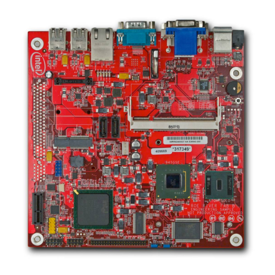
Page 14: Figure 1. Intel ® Atom™ Processor N270 And Mobile Intel ® 945Gse Express Chipset
Getting Started ® ® Figure 1. Intel Atom™ Processor N270 and Mobile Intel 945GSE Express Chipset Board (Top View) Developer’s Kit User Manual... -
Page 15: Development Board Features
Getting Started Development Board Features ® T able 5 provides a list of the major features present on the Intel Atom™ Processor ® N270 and Mobile Intel 945GSE Express Chipset customer reference board. ® ® Table 5. Intel Atom™ Processor N270 and Mobile Intel... -
Page 16: Included Hardware And Documentation
Included Hardware and Documentation This following hardware and documentation is included in the development kit: ® ® • Intel Atom™ Processor N270 and Mobile Intel 945GSE Express Chipset Development Board (Installed) • Firmware Hub (FWH) (Installed) • Combination CPU/GMCH heatsink (Installed) •... -
Page 17: Software Key Features
Getting Started ® Note: Not all peripherals listed will be included with an Intel Atom™ Processor N270 and ® Mobile Intel 945GSE Express Chipset board if it is not obtained as a development kit. Software Key Features The driver CD included in the kit contains all of the software drivers necessary for basic system functionality under the following operating systems: Microsoft Windows XP*, Microsoft Windows XP Embedded*, WinCE 6.0*, and Linux. -
Page 18: Before You Begin
Getting Started Before You Begin The following additional hardware may be necessary to successfully set up and operate the development board. VGA Monitor: Any standard VGA or DVI-D monitor may be used. The setup instructions in this chapter assume the use of a standard VGA monitor, TV, or flat panel monitor. -
Page 19: Theory Of Operation
Theory of Operation Block Diagram ® ® Figure 2. Intel Atom™ Processor N270 and Mobile Intel 945GSE Express Chipset CRB Block Diagram NOTE: Schematic pages are shown for reference in the block diagram. Mechanical Form Factor The development board conforms to the mini-ITX form factor, 6.75” X 6.75” (17 cm X 17 cm). -
Page 20: Thermal Solution
Theory of Operation limit is the range within which the electrical circuits can be expected to meet their specified performance requirements. Operation outside the functional limit can degrade system performance and cause reliability problems potentially including failure of the part and damage to the system. The development kit is shipped with a heatsink thermal solution installed on the processor and chipset. -
Page 21: Intel ® Atom™ Processor N270
ITP converter cable is necessary to use the older ITP tools. Also, in some cases a resistor change rework is necessary to get the older ITP tools to function properly. Please contact local Intel field representative for additional details. 3.5.5... -
Page 22: Mobile Intel 945Gse Express Chipset Gmch
Theory of Operation ® well. The user must use an XDP or ITP interface that is compatible with the Intel Atom™ Processor N270 processor with 512 kB L2 cache. XDP and ITP are backwards- compatible, but a cable adapter is necessary since the connectors for XDP and ITP are different. -
Page 23: Pcie* Mini-Card
The internal USB header can support an internal USB flash drive conforming to the ® mechanical and electrical requirements of the Intel Z-U130 module (2x5 header, standard profile). The flash drive’s activity LED# signal is included in the front panel HDD activity LED output. -
Page 24: Ide
Theory of Operation 3.7.7.1 Peripheral Power Connector There is support for a hard disk drive or optical disk drive. Both 12 VDC and 5 VDC are supplied in either ACPI S0 or S1. Due to total power available, there may be limitations on the simultaneous powering of a hard disk drive (using MB peripheral power connector), or support of a full 15W for the PCI expansion slot. -
Page 25: Gpio
Theory of Operation 3.7.10 GPIO Table 7. ICH GPIOs GPIOx CRB Signal Notes GPIO0 PM_BMBUSY# Bus master busy signal GPIO1 PCI_REQ#5 GPIO2 INT_PIRQE# GPIO3 INT_PIRQF# GPIO4 INT_PIRQG# GPIO5 INT_PIRQH# GPIO6 No connect GPIO7 FP_AUD_DETECT GPIO8 No connect GPIO9 IDE_PDIAG1 GPIO10 No connect GPIO11 SMB_ALERT#... - Page 26 Theory of Operation GPIO23 LDRQ1# LPC DMA master request signal goes to SIO GPIO24 No connect GPIO25 No connect GPIO26 RF_KILL# Active low to kill the WLAN card. GPIO27 YELLOW_LED_CNTRL GPIO28 GREEN_LED_CNTRL GPIO29 USB_OC5# GPIO30 USB_OC6# GPIO31 USB_OC7# GPIO32 PM_CLKRUN# Connects to peripherals that need to prevent clock stop or request clock start.
-
Page 27: Pci Configuration Space
Intel® 945GSE Controller Integrated Graphics Intel 27A6h Graphics Intel® 945GSE Controller Integrated Graphics Intel 27D8h Intel® HD Audio controller Intel 27D0h PCI to PCI ICH7M PCIe* Port 1 Bridge (used for Realtek LAN) Intel 27D2h PCI to PCI ICH7M PCIe* Port 2... -
Page 28: Figure 2. Intel
Theory of Operation Intel 27C4h ICH7M SATA Controller Controller Intel 27DAh ICH7M SMBus Controller Realtk 8168h Ethernet RTL8111C Gbe LAN on Semicondu Controller ICH7M PCIe* Port 1 ctor* [PCIe* PCIe* Mini-card on mini-card] ICH7M PCIe* Port 2 [PCIe* x1 PCIe* x1 slot on... -
Page 29: Hardware Reference
Hardware Reference Hardware Reference Primary Features Figure 3 shows the major components of the CRB. Figure 3. CRB Components Power 12 VDC (+/-5%) input power will be supplied via a rear panel 2 mm [0.08”] connector. Developer’s Kit User Manual... -
Page 30: Power Supply
Standard front panel header (with additional pins for wireless activity LED) ® • Intel High Definition Audio front panel audio header (supporting jack sensing). One headphone, 3.5mm Tip/Ring/Sleeve (TRS) w/Lime Green housing and one microphone, 3.5mm TRS w/ Pink housing. -
Page 31: Back Panel I/O Connectors
Hardware Reference 4.3.2 Back Panel I/O Connectors Figure 5. Back Panel • DC Power In : 12 VDC Power jack • PS/2 Mouse : Green • PS/2 Keyboard : Purple • Graphics : 1 each VGA and DVI-D • Serial Port : 1 each DB-9, (Teal or turquoise color coding) •... -
Page 32: Configuration Settings
Hardware Reference Configuration Settings 4.4.1 Configuration Jumpers/Switches Caution: Do not move jumpers with the power on. Always turn off the power and unplug the power cord from the computer before changing jumper settings. Otherwise, it may damage the board. Note: A jumper consists of two or more pins mounted on the motherboard. When a jumper cap is placed over two pins, it is designated as IN. -
Page 33: Led
Hardware Reference Table 9 lists the LEDs that provide status of various functions on the CRB. Table 9. CRB LEDs Function Reference Designator DCIN – RED +5VA – RED +5VS – YELLOW +2.5S – GREEN +3.3S – YELLOW § Developer’s Kit User Manual... -
Page 34: Software
Software Software EFI Firmware 5.1.1 Overview The EFI firmware is stored on an 8Mb SPI part. The EFI setup utility for changing the date, enabling/disabling peripherals, and boot order is accessed during POST by pressing the <F2> key. 5.1.2 EFI Setup Security EFI setup entry password protection options are available for both the Administrator and End-User. -
Page 35: Quick Start
Quick Start Quick Start The following sections summarize the necessary hardware and power-on instructions ® ® for the Intel Atom™ Processor N270 and Mobile Intel 945GSE Express Chipset Development Kit. Required Peripherals • DDR2-533 SDRAM SO-DIMM (included in kit) •... - Page 36 3. If the system is hung, it is possible to asynchronously shut the system down by pressing the power-button continuously for 4 seconds. Caution: Intel does not recommend powering down the board by removing power to the DC power supply or disconnecting the DC input from the board.
Need help?
Do you have a question about the Atom N270 and is the answer not in the manual?
Questions and answers