
Related Manuals for Hobart Welding Products Handler 187


Summary of Contents for Hobart Welding Products Handler 187
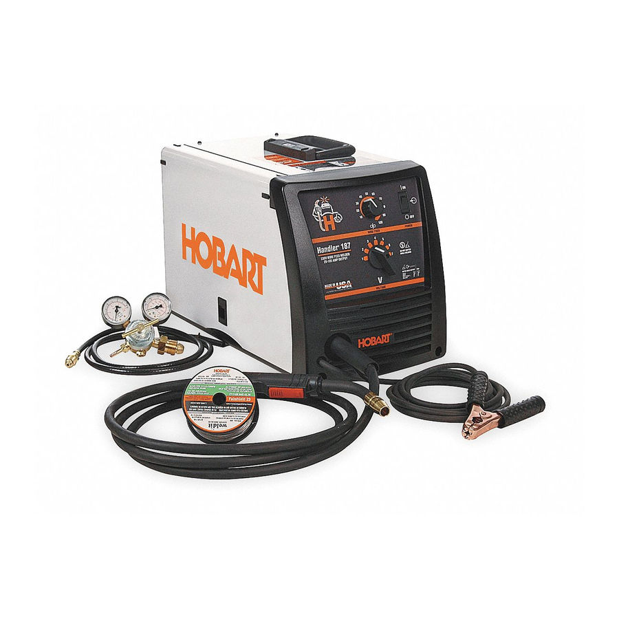
- Page 1 OM-228 187B 2010−01 Processes MIG (GMAW) Welding Flux Cored (FCAW) Welding Description Arc Welding Power Source And Wire Feeder Handler 187 And H100S2−10 Gun...
- Page 2 From Hobart to You Thank you and congratulations on choosing Hobart. Now you can get the job done and get it done right. We know you don’t have time to do it any other way. This Owner’s Manual is designed to help you get the most out of your Hobart products.
-
Page 3: Table Of Contents
TABLE OF CONTENTS SECTION 1 − SAFETY PRECAUTIONS - READ BEFORE USING ........1-1. - Page 4 TABLE OF CONTENTS SECTION 9 − MIG WELDING (GMAW) GUIDELINES ..........9-1.
-
Page 5: Section 1 − Safety Precautions - Read Before Using
SECTION 1 − SAFETY PRECAUTIONS - READ BEFORE USING som _2009−08 Protect yourself and others from injury — read and follow these precautions. 1-1. Symbol Usage DANGER! − Indicates a hazardous situation which, if Indicates special instructions. not avoided, will result in death or serious injury. The possible hazards are shown in the adjoining symbols or explained in the text. - Page 6 D Remove stick electrode from holder or cut off welding wire at FUMES AND GASES can be hazardous. contact tip when not in use. D Wear oil-free protective garments such as leather gloves, heavy Welding produces fumes and gases. Breathing shirt, cuffless trousers, high shoes, and a cap.
-
Page 7: Additional Symbols For Installation, Operation, And Maintenance
1-3. Additional Symbols For Installation, Operation, And Maintenance FIRE OR EXPLOSION hazard. MOVING PARTS can injure. D Do not install or place unit on, over, or near D Keep away from moving parts such as fans. combustible surfaces. D Keep all doors, panels, covers, and guards D Do not install unit near flammables. -
Page 8: California Proposition 65 Warnings
1-4. California Proposition 65 Warnings For Gasoline Engines: Welding or cutting equipment produces fumes or gases which contain chemicals known to the State of California to Engine exhaust contains chemicals known to the State of cause birth defects and, in some cases, cancer. (California California to cause cancer, birth defects, or other reproduc- Health &... -
Page 9: Section 2 − Consignes De Sécurité − Lire Avant Utilisation
SECTION 2 − CONSIGNES DE SÉCURITÉ − LIRE AVANT UTILISATION fre_som_2009−08 Se protéger et protéger les autres contre le risque de blessure — lire et respecter ces consignes. 2-1. Symboles utilisés DANGER! − Indique une situation dangereuse qui si on Indique des instructions spécifiques. - Page 10 Il reste une TENSION DC NON NÉGLIGEABLE dans D Porter des vêtements confectionnés avec des matières résistan- tes et ignifuges (cuir, coton lourd ou laine) et des bottes de les sources de soudage onduleur UNE FOIS protection. l’alimentation coupée. LE SOUDAGE peut provoquer un D Arrêter les convertisseurs, débrancher le courant électrique et incendie ou une explosion.
-
Page 11: Dangers Supplémentaires En Relation Avec L'installation, Le Fonctionnement Et La Maintenance
ACCUMULATIONS LES BOUTEILLES peuvent exploser risquent de provoquer des blessures si elles sont endommagées. ou même la mort. Des bouteilles de gaz protecteur contiennent du gaz sous haute pression. Si une bouteille est endom- D Fermer l’alimentation du gaz protecteur en cas magée, elle peut exploser. -
Page 12: Proposition Californienne 65 Avertissements
Les PIÈCES MOBILES peuvent RAYONNEMENT HAUTE causer des blessures. FRÉQUENCE (H.F.) risque provoquer des interférences. D Ne pas s’approcher des organes mobiles. D Ne pas s’approcher des points de coincement D Le rayonnement haute fréquence (H.F.) peut tels que des rouleaux de commande. provoquer des interférences avec les équi- pements de radio−navigation et de com- munication, les services de sécurité... -
Page 13: Principales Normes De Sécurité
2-5. Principales normes de sécurité Safety in Welding, Cutting, and Allied Processes, ANSI Standard Z49.1, 25 West 43rd Street, New York, NY 10036 (téléphone : 212-642-4900, de Global Engineering Documents (téléphone : 1-877-413-5184, site site Internet : www.ansi.org). Internet : www.global.ihs.com). Standard for Fire Prevention During Welding, Cutting, and Other Hot Safe Practices for the Preparation of Containers and Piping for Welding Work, NFPA Standard 51B, de National Fire Protection Association,... - Page 14 OM-228 187 Page 10...
-
Page 15: Section 3 − Definitions
SECTION 3 − DEFINITIONS 3-1. Symbols And Definitions Amperage Voltage Hertz Negative Direct Current Positive Single Phase Input (DC) Output Voltage Input Do Not Switch Gas Metal Arc Flux Cored Arc Wire Feed While Welding Welding (GMAW) Welding (FCAW) SECTION 4 − SPECIFICATIONS 4-1. -
Page 16: Duty Cycle And Overheating
4-2. Duty Cycle And Overheating Duty Cycle is percentage of 10 minutes that unit can weld at rated load without overheating. If unit overheats, thermostat(s) opens, output stops, and cooling fan runs. Wait fifteen minutes for unit to cool. Reduce amperage or duty cycle before welding. -
Page 17: Section 5 − Installation
SECTION 5 − INSTALLATION 5-1. Installing Nozzle, Contact Tip, And Adapter Turn off welding power source. Nozzle Contact Tip Head Tube Tip Adapter Wire size stamped on tip − check and match wire size. 8 mm Tools Needed: 8 mm 246 669-A 5-2. -
Page 18: Installing Work Clamp
5-3. Installing Work Clamp Work Cable From Unit Work Clamp Screw Work Clamp Tabs Connection hardware must be tightened with proper tools. Do not just Bend tabs around work cable. hand tighten hardware. A loose electrical connection will cause poor weld performance and excessive heating of the work clamp. -
Page 19: Process/Polarity Table
5-4. Process/Polarity Table Cable Connections Process Polarity Cable To Gun Cable To Work GMAW − Solid wire with shield- DCEP − Reverse polarity Connect to positive (+) out- Connect to negative (−) output ing gas put terminal terminal FCAW − Self-shielding wire − DCEN −... -
Page 20: Installing Gas Supply
5-6. Installing Gas Supply Obtain gas cylinder and chain to running gear, wall, other stationary support so cylinder cannot fall and break off valve. DO NOT use Argon/Mixed gas regulator/flowmeter with CO shielding gas. See Parts List for optional Cylinder Valve gas regulator/flowmeter. -
Page 21: Selecting A Location And Connecting Input Power
5-7. Selecting A Location And Connecting Input Power Special installation may be required where gasoline or volatile liquids are present − see NEC Article 511 or CEC Section 20. Installation must meet all Na- tional and Local Codes − 18 in. (457 mm) of have only qualified persons space for airflow make this installation. -
Page 22: Electrical Service Guide
5-8. Electrical Service Guide Failure to follow these electrical service guide recommendations could create an electric shock or fire hazard. These recommenda- tions are for a dedicated branch circuit sized for the rated output and duty cycle of the welding power source. Input Voltage (V) Input Amperes (A) At Rated Output 20.5... -
Page 23: Threading Welding Wire
5-10. Threading Welding Wire Wire Spool Welding Wire Inlet Wire Guide Pressure Adjustment Knob Drive Roll Gun Conduit Cable Lay gun cable out straight. Tools Needed: Hold wire tightly to keep it from unraveling. 4 in. (120 mm) 6 in. (150 mm) Open pressure assembly. -
Page 24: Section 6 − Operation
SECTION 6 − OPERATION 6-1. Controls Ref. 228 178-A / Ref. 246 668-A Wire Speed Control Voltage Switch Switch must “click” into detent Use control to select a wire feed speed. As position. Voltage switch setting increases, wire The higher the selected number, the speed range also increases (see weld thicker the material that can be welded Trigger Switch... - Page 25 Notes OM-228 187 Page 21...
-
Page 26: Weld Parameter Chart For 230 Vac Model
6-2. Weld Parameter Chart 1/35 Flux Cored E71T−11 Good for windy or 1/30 “Set Polarity outdoor applications for (DCEN)” Solid Wire 1/30 2/40 ER70S−6 “Set Polarity Produces less spatter. 1/40 for (DCEP)” Better appearance 3/40 Solid Wire ER70S−6 “Set Polarity for (DCEP)”... - Page 27 1/40 2/40 4/60 5/40 6 / 40* 1/35 2/40 3/50 5/50 6/60 7 / 60* 1/25 3/30 4/35 5/35 6 / 35* 3/50 4/60 5/80 6/90 2/50 3/50 5/60 6/60 6 / 70* 7 / 80* 4/40 5/40 5/50 6/50 7 / 50* 7 / 60* 3/35...
-
Page 28: Section 7 − Maintenance & Troubleshooting
SECTION 7 − MAINTENANCE & TROUBLESHOOTING 7-1. Routine Maintenance Disconnect power before maintaining. 3 Months Replace Repair or Clean unreadable replace tighten weld labels. cracked terminals. weld cable. 6 Months Blow out or vacuum inside. During heavy service, clean monthly. 7-2. -
Page 29: Changing Drive Roll Or Wire Inlet Guide
7-4. Changing Drive Roll Or Wire Inlet Guide Turn off welding power source. Inlet Wire Guide Securing Screw Inlet Wire Guide Loosen screw. Slide tip as close to drive rolls as possible without touching. Tighten screw. Retaining Pin To remove drive roll, push drive roll in and rotate it (1/4 turn) to the open slot and slide it out over the retaining pin. -
Page 30: Changing Nozzle, Contact Tip, Adapter And Liner, And Cleaning Gun Casing
7-5. Changing Nozzle, Contact Tip, Adapter And Liner, And Cleaning Gun Casing Turn off welding power source. Nozzle Contact Tip Tip Adapter Head Wire size stamped on tip − check Tube and match wire size. Cut off wire and 8 mm disconnect gun from feeder. -
Page 31: Replacing Switch And/Or Head Tube
7-6. Replacing Switch And/Or Head Tube Turn Off welding power source /wire feeder and disconnect gun. Remove handle halves. Remove screws (5) and nuts (4). Remove switch housing. Install new Remove screw on switch and connect leads (polarity is opposite side. important). -
Page 32: Troubleshooting Table
7-7. Troubleshooting Table Trouble Remedy Secure power cord plug in receptacle (see Section 5-7). No weld output; wire does not feed; fan does not run. Replace building line fuse or reset circuit breaker if open. Place Power switch in On position (see Section 6-1). Reset welding power source supplementary protector (see Section 7-2). - Page 33 Notes OM-228 187 Page 29...
-
Page 34: Section 8 − Electrical Diagram
SECTION 8 − ELECTRICAL DIAGRAM Figure 8-1. Circuit Diagram OM-228 187 Page 30... - Page 35 228 180-A OM-228 187 Page 31...
-
Page 36: Section 9 − Mig Welding (Gmaw) Guidelines
SECTION 9 − MIG WELDING (GMAW) GUIDELINES mig1_2009−12 / Ref. 801 909-A 9-1. Typical MIG Process Connections Weld current can damage electronic parts in vehicles. Disconnect both battery cables before welding on a vehicle. Place work clamp as close to the weld as possible. Regulator/ Flowmeter Wire Feeder/... -
Page 37: Typical Mig Process Control Settings
9-2. Typical MIG Process Control Settings These settings are guidelines only. Material and wire type, joint design, fitup, position, shielding gas, etc. affect settings. Test welds to be sure they comply to specifications. Material thickness determines weld parameters. 1/8 or 0.125 in. Convert Material Thickness to Amperage (A) -
Page 38: Holding And Positioning Welding Gun
9-3. Holding And Positioning Welding Gun Welding wire is energized when gun trigger is pressed. Before lowering helmet and pressing trigger, be sure wire is no more than 1/2 in. (13 mm) past end of nozzle, and tip of wire is positioned correctly on seam. Hold Gun and Control Gun Trigger Workpiece... -
Page 39: Conditions That Affect Weld Bead Shape
9-4. Conditions That Affect Weld Bead Shape Weld bead shape depends on gun angle, direction of travel, electrode extension (stickout), travel speed, thickness of base metal, wire feed speed (weld current), and voltage. Push Drag Perpendicular GUN ANGLES AND WELD BEAD PROFILES Short Normal Long... -
Page 40: Gun Movement During Welding
9-5. Gun Movement During Welding Normally, a single stringer bead is satisfactory for most narrow groove weld joints; however, for wide groove weld joints or bridging across gaps, a weave bead or multiple stringer beads works better. Stringer Bead − Steady Movement Along Seam Weave Bead −... -
Page 41: Troubleshooting − Excessive Spatter
9-8. Troubleshooting − Excessive Spatter Excessive Spatter − scattering of molten metal particles that cool to solid form near weld bead. S-0636 Possible Causes Corrective Actions Wire feed speed too high. Select lower wire feed speed. Voltage too high. Select lower voltage range. Electrode extension (stickout) too long. -
Page 42: Troubleshooting − Lack Of Penetration
9-11. Troubleshooting − Lack Of Penetration Lack Of Penetration − shallow fusion between weld metal and base metal. Lack of Penetration Good Penetration S-0638 Possible Causes Corrective Actions Improper joint preparation. Material too thick. Joint preparation and design must provide access to bottom of groove while maintaining proper welding wire extension and arc characteristics. -
Page 43: Troubleshooting − Waviness Of Bead
9-14. Troubleshooting − Waviness Of Bead Waviness Of Bead − weld metal that is not parallel and does not cover joint formed by base metal. S-0641 Possible Causes Corrective Actions Welding wire extends too far out of nozzle. Be sure welding wire extends not more than 1/2 in (13 mm) beyond nozzle. Unsteady hand. -
Page 44: Common Mig Shielding Gases
9-16. Common MIG Shielding Gases This is a general chart for common gases and where they are used. Many different combinations (mixtures) of shielding gases have been developed over the years. The most commonly used shielding gases are listed in the following table. - Page 45 Problem Probable Cause Remedy Wire slipping in drive rolls. Adjust pressure setting on wire feed rolls. Replace worn Welding arc not stable. drive rolls if necessary. Wrong size gun liner or contact tip. Match liner and contact tip to wire size and type. Incorrect voltage setting for selected wire feed speed on Readjust welding parameters.
-
Page 46: Section 10 − Parts List
SECTION 10 − PARTS LIST Hardware is common and not available unless listed. 804 624-A Figure 10-1. Main Assembly OM-228 187 Page 42... - Page 47 Item Dia. Part Mkgs. Description Quantity Figure 10-1. Main Assembly ....199 566 DOOR, access ..........
- Page 48 Item Dia. Part Mkgs. Description Quantity Figure 10-1. Main Assembly (Continued) ....196 574 SWITCH, rocker DPST ......... .
- Page 49 246 670-A Figure 10-2. H100S2-10 Gun Item Dia. Part Mkgs. Description Quantity 245 924 Figure 10-2. H100S2-10 Gun ... . . 169 715 NOZZLE, slip type .500 orf flush ........
- Page 50 10-3. Optional Drive Rolls For All Feed Head Assemblies WIRE DIAMETER PART NO. INCHES (mm) 237 338 .023/.025 (.6) and .030/.035 (.8 and .9) 202 926 .030/.035 (.8 and .9) and .045 (1.2 VK Groove) 10-4. Options PART NO. DESCRIPTION REMARKS 770 187 Running Gear/Cylinder Rack...
- Page 51 Effective January 1, 2009 5/3/1 WARRANTY applies to all Hobart welding equipment, plasma cutters and spot welders with a Warranty Questions? serial number preface of LK or newer. Call This limited warranty supersedes all previous Hobart warranties and is exclusive with 1-800-332-3281 no other guarantees or warranties expressed or implied.
- Page 52 Contact the Delivering Carrier to: File a claim for loss or damage during shipment. For assistance in filing or settling claims, contact your distributor and/or equipment manufacturer’s Transportation Department. ORIGINAL INSTRUCTIONS − PRINTED IN USA 2009 Hobart Welding Products. 2009−01...
Need help?
Do you have a question about the Handler 187 and is the answer not in the manual?
Questions and answers