Table of Contents
Advertisement
Advertisement
Table of Contents

Related Manuals for Friedrich Kuhl SQ05N10 Series


Summary of Contents for Friedrich Kuhl SQ05N10 Series
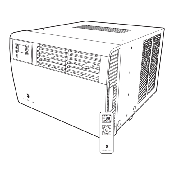
- Page 1 2 0 1 2 Room Air Conditioners SYSTEM FAN MODE POWER FAN SPEED SCHEDULE Q Chassis Models 115-Volt: SQ05N10*, SQ06N10*, SQ08N10*, SQ10N10* Cool Only 115-Volt: EQ08N11* Cool and Electric Heat KuhlQ_Serv/Parts Man (4-12) Last character may vary. 93001401_01...
-
Page 2: Table Of Contents
Table Of Contents Important Safety Information ............................2-4 Introduction ..................................4 Performance Data ................................6 Installation Information/Sleeve Dimensions ........................6 Electrical Data ................................... 7 Before Operating the Unit ..............................8 Kuhl Q Control Options ..............................10 Control Panel Operation Instructions .......................... 11-17 Electronic Control Sequence of Operation ......................... -
Page 3: Important Safety Information
IMPORTANT SAFETY INFORMATION with the safety procedures required for installation and repair, and who is equipped with the proper tools and test instruments required to service this product. shock which can be serious or even fatal. Safety warnings have been placed throughout this manual to alert you to potential hazards that may be encountered. - Page 4 Do not spray or pour water on the return air grille, discharge air grille, evaporator coil, control panel, and sleeve on the room side of the air conditioning unit while cleaning. Electrical component malfunction caused by water could result in electric shock or other electrically unsafe conditions when the power is restored and the unit is turned on, even after the exterior is dry.
-
Page 5: Introduction
Model information can be found on the name plate behind the front cover. Please complete and mail the owner registration card furnished with this product, or register online at www.friedrich. com. For your convenience, record the model information here. FRIEDRICH AIR CONDITIONING CO. -
Page 6: Unit Identification
UNIT IDENTIFICATION KuhlQ Model Number Code S Q 08 N 1 0 A 1st Digit – Function E = Electric Heat S = Straight Cool 7th Digit – Options 0 = Straight Cool 1 = 1 KW Heat Strip, Nominal 2nd Digit Q = Chassis Size 6th Digit –... -
Page 7: Performance Data
7500 4000 11.2 1290 11.7 As an ENERGY STAR partner, Friedrich Air Conditioning Co. has determined that the selected ENERGY STAR models ® ® meet the ENERGY STAR ® Estimated yearly operating cost based on a 2007 national average electricity cost of 10.65 cents per kWh. -
Page 8: Electrical Data
ELECTRICAL DATA WARNING ELECTRIC SHOCK HAZARD Turn off electric power before service or installation. All electrical connections and wiring MUST be the National Electrical Code and all local codes death. NOTICE FIRE HAZARD electically unsafe conditions which could cause moderate or serious property damage. -
Page 9: Before Operating The Unit
Test the power cord SQ08 SQ10 5-15P EQ08 All Friedrich room air conditioners are shipped from the factory with a Leakage Current Detection Interrupter (LCDI) equipped power cord. The Table 1. LCDI device meets the UL and NEC requirements for cord connected air conditioners effective August 2004. - Page 10 Kuhl Q Control Panel Operation Let’s check out how to control your air conditioner. On the control panel, just above the POWER , is a liquid crystal display (LCD). All of the control panel function buttons and mode icons can be viewed in Figure 6. Power On –...
-
Page 11: Kuhl Q Control Options
07:00 and 18:00. This option will cause your air conditioner to raise temperatures FriedrichLink™ Adapter accessory available through Friedrich authorized to 84°F after typical working hours and on weekends when commercial spaces retailers or www.friedrich.com. See FriedrichLink™ Adapter section on are typically unoccupied. www.friedrich.com for complete details. -
Page 12: Control Panel Operation Instructions
Control Panel Operation Instructions FAN MODE – The button allows you to select between MODE modes. To select, press once and let go. SYSTEM - The button allows you to sequentially select three modes SYSTEM of operation. To select, press once and let go. COOL MODE HEAT MODE Not available on some models... - Page 13 ºF - ºC Select and DOWN - arrows - Pressing either button changes the system's set point (desired room temperature). These buttons are also used for setting the Timer and other programming. FRR132 To switch from degrees Fahrenheit (F) to Celsius (C), press FRR100 buttons simultaneously for three seconds.
- Page 14 DIM Function Wait Icon There are three separate display brightness levels, AUTO, 20% and full (100%). To change the DIM setting, press the Power button for three seconds. FRR120 The wait icon illuminates when the compressor lockout is active. Control Panel Lock FRR192 The 1 indicates a DIM setting of Auto (factory default on new units).
- Page 15 TIMER OR SCHEDULE OPTIONS 1 OR 2 SELECTION The control system has one Timer and two Schedule functions: Timer (factory default) - Allows you to command the unit to turn ON and OFF at a time you program. Setting the start, stop and day can be found latter in this manual on page 15.
- Page 16 Button inactivity for more than 15 seconds causes the display to time out and return to the normal operating display. TIMER HOUR Timer Start Time FRIEDRICH AIR CONDITIONING CO. SAN ANTONIO, TX FRR097 SET TIME AND DAY - To adjust the unit's time press and hold the HOUR and the MIN buttons for three seconds (Refer to Figure 4).
- Page 17 Set theTimer Stop Time Timer ON Scenarios Scenario 1 FRR144 The display shows a normal system. Press and hold the MIN button (Figure 4) for 3 seconds. Note the Timer start - stop times may be set even when FRR156 The display shows a normal operating system.
- Page 18 Timer OFF Scenarios Scenario 1 Timer - Schedule Control Block FRR166 FRR148 The display shows the unit in Timer mode during an in-active (OFF) period. If the unit is operating in the TIMER or SCHEDULE mode, and you press any bytton except the button, the TIMER icon begins to TIMER...
-
Page 19: Remote Control Operation
Remote Control Operation FAN SPEED Button - Used to sequentially select new fan speed, plus AUTO operation. When the button is pressed, the fan speed icon SPEED (triangle) changes to indicate the new speed level. Fan speed automatically Remote Control - Refer to Figures 10 and 11 during operation description. varies depending on the set temperature on the control panel and the actual Getting Started - Install two (2) AAA batteries in the battery compartment room temperature. - Page 20 Figure 10 DISPLAY SYSTEM FAN MODE SYSTEM FAN MODE POWER TEMPERATURE POWER TEMPERATURE DOWN FAN SPEED SCHEDULE SCHEDULE FAN SPEED FRR081 Figure 11 COOL FAN ONLY HEAT ICON ICON ICON SYSTEM MODE MODE SPEED °F / °C ICONs SCHEDULE ICON FRR082...
-
Page 21: Electronic Control Sequence Of Operation
ELECTRONIC CONTROL SEQUENCE OF OPERATION Cooling Mode prior to the compressor. Once the ambient temperature has been lowered to .25 F below the set point, the cooling cycle starts to terminate by shutting off the compressor. After a 30 seconds delay, the fan is shut off. (See figure below for graphic details) Electric Heat Operation in Cool with Electric Heat Units When in the Heat mode, with and without Fan Mode Auto (Fan cycling):... - Page 22 ELECTRONIC CONTROL SEQUENCE OF OPERATION (CONT.) Compressor Lock Out Time The lockout feature ensures that the compressor is de-energized for a period of time. The timer varies randomly from 180 to 240 seconds The compressor lockout is initiated every time the compressor is “off” due to: (1) Satisfying the temperature set point (2) Changing mode to fan only or heat (3) Turning the unit off...
-
Page 23: Components Testing
COMPONENTS TESTING Testing the User Interface and Relay Board WARNING ELECTRIC SHOCK HAZARD Turn off electric power before inspections, maintenances, or service. Failure to do so could result in serious injury or death. If the user interface does not turn on: 1. - Page 24 COMPONENTS TESTING (CON’T) Testing the Relay Board Heat Relay For Heat & Cool Units Fuse Goes Here T 3.15AH 250 Volts AC High Speed Med Speed Low Speed Indoor Coil Outdoor Coil Thermistor Thermistor Test here for 5VDC. If no voltage or wrong voltage, replace relay board.
-
Page 25: Capacitor Check With Capacitor Analyzer
COMPONENTS TESTING (Continued) FAN MOTOR A single phase permanent split capacitor motor is used to drive Many motor capacitors are internally fused. Shorting the the evaporator blower and condenser fan. A self-resetting terminals will blow the fuse, ruining the capacitor. A 20,000 overload is located inside the motor to protect against high ohm 2 watt resistor can be used to discharge capacitors temperature and high amperage conditions. - Page 26 COMPONENTS TESTING (Continued) HEATING ELEMENT (See Figure) DRAIN PAN VALVE All electric heat models are equipped with a heating element. During the cooling mode of operation, condensate which The EQ08 has a 1.15 KW element. collects in the drain pan is picked up by the condenser fan blade and sprayed onto the condenser coil.
-
Page 27: Refrigeration Sequence Of Operation
REFRIGERATION SEQUENCE OF OPERATION A good understanding of the basic operation of the The refrigerant leaves the condenser Coil through the refrigeration system is essential for the service technician. liquid line as a warm high pressure liquid. It next will pass Without this understanding, accurate troubleshooting of through the refrigerant drier (if so equipped). -
Page 28: R-410A Sealed System Repair Considerations
R-410A SEALED SYSTEM REPAIR CONSIDERATIONS WARNING Refrigeration system under high pressure service this equipment. R410A systems operate at higher pressures than R22 equipment. Appropriate safe service and handling practicces must be used. Only use gauge sets designed for use with R410A. Do not use standard R22 gauge sets. -
Page 29: Sealed Refrigeration System Repairs
R-410A SEALED REFRIGERATION SYSTEM REPAIRS IMPORTANT SEALED SYSTEM REPAIRS TO COOL-ONLY MODELS REQUIRE THE INSTALLATION OF A LIQUID LINE DRIER. EQUIPMENT REQUIRED: 1. Voltmeter 10. Low Pressure Gauge - (-30 to 200 lbs.) 2. Ammeter 11. Vacuum Gauge - (0 - 1000 microns) 3. - Page 30 REFRIGERATION SEQUENCE OF OPERATION A good understanding of the basic operation of the The refrigerant leaves the condenser Coil through the refrigeration system is essential for the service technician. liquid line as a warm high pressure liquid. It next will pass Without this understanding, accurate troubleshooting of through the refrigerant drier (if so equipped).
-
Page 31: Refrigerant Charging
R-410A SEALED REFRIGERATION SYSTEM REPAIRS IMPORTANT SEALED SYSTEM REPAIRS TO COOL-ONLY MODELS REQUIRE THE INSTALLATION OF A LIQUID LINE DRIER. EQUIPMENT REQUIRED: 1. Voltmeter 10. Low Pressure Gauge - (-30 to 200 lbs.) 2. Ammeter 11. Vacuum Gauge - (0 - 1000 microns) 3. - Page 32 Method Of Charging / Repairs The acceptable method for charging the RAC system is the Weighed in Charge Method. The weighed in charge method is applicable to all units. It is the preferred method to use, as it is the most accurate. The weighed in method should always be used whenever a charge is removed from a unit such as for a leak repair, compressor replacement, or when there is no refrigerant...
-
Page 33: Undercharged Refrigerant Systems
WARNING WARNING HIGH PRESSURE HAZARD ELECTRIC SHOCK HAZARD Turn off electric power before service or Sealed Refrigeration System contains refrigerant installation. and oil under high pressure. Extreme care must be used, if it becomes Proper safety procedures must be followed, necessary to work on equipment with power and proper protective clothing must be worn applied. -
Page 34: Restricted Refrigerant System
Restricted Refrigerant System Troubleshooting a restricted refrigerant system can be at the metering device entrance to the evaporator. The The following procedures are the more common evaporator in a partial restriction could be partially frosted problems and solutions to these problems. There are two or have an ice ball close to the entrance of the metering types of refrigerant restrictions: Partial restrictions and device. -
Page 35: Compressor Checks
COMPRESSOR CHECKS External Overload WARNING The compressor is equipped with an external overload which senses both motor amperage and winding tem- ELECTRIC SHOCK HAZARD perature. High motor temperature or amperage heats the Turn off electric power before service or installation. Extreme care must be used, if it overload causing it to open, breaking the common circuit becomes necessary to work on equipment with within the compressor. -
Page 36: Compressor Checks
Single Phase Resistance Test Remove the leads from the compressor terminals and set Many compressor failures are caused by the following the ohmmeter on the lowest scale (R x 1). conditions: Touch the leads of the ohmmeter from terminals common to start (“C”... -
Page 37: Compressor Replacement
COMPRESSOR REPLACEMENT Recommended procedure for compressor After all refrigerant has been recovered, disconnect replacement suction and discharge lines from the compressor and remove compressor. Be certain to have both suction and discharge process tubes open to atmosphere. WARNING Carefully pour a small amount of oil from the suction RISK OF ELECTRIC SHOCK Unplug and/or disconnect all electrical power stub of the defective compressor into a clean container. -
Page 38: Available Accessories
KWWHTQA - Q Model Decorative Front Cover in Designer White EXPLOSION HAZARD The use of nitrogen requires a pressure See www.friedrich.com for additional accessories for your unit. regulator. Follow all safety procedures and wear protective safety clothing etc. Failure to follow proper safety procedures Recover all refrigerant and oil from the system. -
Page 39: Standard Filter Cleaning/Installation Instructions
Standard Filter Cleaning / Installation Instructions STEP 2. Clean the front frame by washing the dirt from the lter. Use a STEP 1. Swing the door open and remove the lter by grasping the mild soap solution if necessary. Allow lter to dry. lter grip and pushing the lter holder upward and outward. -
Page 40: Routine Maintenance
ROUTINE MAINTENANCE DECORATIVE FRONT COVER WARNING The decorative front and discharge air grille may be cleaned with a mild soap or detergent. Do NOT use ELECTRIC SHOCK HAZARD solvents or hydrocarbon based cleaners such as Turn off electric power before inspections, acetone, naphtha, gasoline, benzene, etc., to clean maintenances, or service. -
Page 41: Relay Board
ROUTINE MAINTENANCE (Continued) NOTICE Do not drill holes in the bottom of the drain pan or the underside of the unit. Not following this notice could result in damage to the unit or condensate water leaking inappropriately which could cause water damage to surrounding property. -
Page 42: After Maintenance/Repair Start-Up Checklist And Notes
Ensure that the entire installation is in compliance with all applicable national and local codes and ordinances having jurisdiction. All air conditioners make some noise. Friedrich units are designed to Secure components and accessories, such as a decorative front operate as quietly as possible. An air conditioner mounted in a wall is quieter cover. -
Page 44: How To Check The Diagnostic Codes
How to Check the Diagnostic Codes Erasing the Diagnostic Codes See codes chart on next page. To check the active system errors, press the & keys for 3 sec. Press and hold the buttons simultaneously for 3 sec. TIMER SPEED SCHEDULE An “E”... -
Page 45: Error Codes
ERROR CODES Error Problem Control Board's Action Code Front Panel Button Stuck For More Continue to monitor for "OPEN" (Unstuck) switch. Do not process switch Than 20 Seconds input. Input Voltage Out of Specification (103 Open all relays until voltage is back within specs. Resume operation - 127 / 187 - 253) Indoor Temperature Sensor is Open or Set temp to 75°F in COOLING or 68°F in HEATING. -
Page 46: Compressor Test Mode
Test Mode This function is used to test the compressor operation. By turning it on, it allows the service technician to bypass the compressor’s 3 minute time delay. Press the & buttons simultaneously for 3 seconds. TIMER SCHEDULE MODE SPEED This will activate the test mode. - Page 49 COOLING ONLY ROOM AIR CONDITIONERS: TROUBLESHOOTING TIPS...
- Page 50 COOLING ONLY ROOM AIR CONDITIONERS: TROUBLESHOOTING TIPS...
- Page 51 COOLING ONLY ROOM AIR CONDITIONERS: TROUBLESHOOTING TIPS...
- Page 52 COOLING ONLY ROOM AIR CONDITIONERS: TROUBLESHOOTING TIPS...
- Page 53 HEAT / COOL ONLY ROOM AIR CONDITIONERS: TROUBLESHOOTING TIPS NOTE: Heater size on the EQ08M11 is: 1.15 KW.
- Page 54 ELECTRONIC CONTROLS COOL ONLY SQ05N10-A, SQ06N10-A, SQ08N10-A, SQ10N10-A...
-
Page 55: Wiring Diagrams
ELECTRONIC CONTROLS COOL WITH ELECTRIC HEAT MODELS EQ08M11-A WIRING DIAGRAM USER INTERFACE INDOOR AMBIENT SENSOR (WHITE) COMPRESSOR TERMINAL ORIENTATION MAY VARY. REFER TO MARKINGS ON COMPRESSOR. OUTDOOR COIL SENSOR (BLUE) COMPRESSOR INDOOR COIL SENSOR (GREEN) RELAY BOARD SUPPLY CORD BLUE OVLD BLACK BLACK... -
Page 56: Thermistor Resistance Values
THERMISTORS’ RESISTANCE VALUES (This Table Applies to All Thermistors) TEMP RESISTENCE TEMP RESISTENCE (K Ohms) (K Ohms) 56.4452 9.2133 49.6839 9.0275 43.8591 8.8459 38.8118 8.6683 34.4303 8.4947 30.6103 8.3250 29.9068 8.1593 29.2218 7.9973 28.5546 7.8388 27.9048 7.6839 27.2717 7.5324 26.6550 7.3841 26.0540 7.2391... -
Page 59: Heat Load Form
HEAT LOAD FORM The heat load form on the following page may be used by Following is an example using the heat load form: servicing personnel to determine the heat loss of a conditioned A space to be conditioned is part of a house geographically space and the ambient winter design temperatures in which located in an area where the lowest outdoor ambient winter the unit will heat the calculated space. - Page 60 HEATING LOAD FORM FRIEDRICH ROOM UNIT HEAT PUMPS BTU/HR PER F ° WALLS: 2” Insulation Lin. Ft. x 1.6 Average Lin. Ft. x 2.6 WINDOWS & DOORS (Area, sq. ft.) Single Glass: Sq. Ft. x 1.13 Double Glass: Sq. Ft. x 0.61 Lin.
-
Page 61: Parts List
Kühl-Q Chassis 2012 Parts List... - Page 62 Kühl-Q Units’ 2012 Parts List...
- Page 63 61080594 CAPACITOR 55/7.5 MF 370V 2.0 62601029 KIT REMOTE CONTROL RPLMNT SVC KUHL 61818523 EXPANDED METAL GRILLE PAINTED KUHLQ 60169120 SCRIPT FRIEDRICH 2010 "FESTOON" 62601027 KIT SENSOR RPLMNT SVC KUHL Q (THERMISTOR SET) 03760545 CAPILLARY TUBE 03760568 CAPILLARY TUBE 03760513...
-
Page 64: Addendum 1
Addendum 1 Schedule Table with Energy Saving Values Pre Programmed Residential Schedule Option 3 Period Tues Thur Start Time Start Time Start Time Start Time Start Time Start Time Start Time System Mode Cool System Mode Cool System Mode Cool System Mode Cool System Mode Cool System Mode Cool System Mode... -
Page 65: Warranty
FIRST YEAR ANY PART: If any part supplied by FRIEDRICH fails because of a defect in workmanship or material within twelve months from date of original purchase, FRIEDRICH will repair the product at no charge, provided room air conditioner is reasonably accessible for service. Any additional labor cost for removing inaccessible units and/or charges for mileage related to travel by a Service Agency that exceeds 25 miles one way will be the responsibility of the owner. -
Page 66: Parts Depots
CUSTOMER SATISFACTION and QUALITY ASSURANCE Friedrich is a conscientious manufacturer, concerned about customer satisfaction, product quality, and controlling warranty costs. As an Authorized Service Provider you play a vital role in these areas. By adhering to the policies and procedures you provide us with vital information on each warranty repair you complete. - Page 67 FRIEDRICH AIR CONDITIONING CO. 10001 Reunion Place, Ste. 500, San Antonio, TX 78216 P 210-546-0500 | F 210-546-0731 www.friedrich.com Printed in the U.S.A. KuhlQ-Serv/PartsMan (5-12)
Need help?
Do you have a question about the Kuhl SQ05N10 Series and is the answer not in the manual?
Questions and answers