Table of Contents
Advertisement
Advertisement
Table of Contents

Related Manuals for ECS AMD690GM-M2


Summary of Contents for ECS AMD690GM-M2
- Page 3 Preface Copyright This publication, including all photographs, illustrations and software, is protected under international copyright laws, with all rights reserved. Neither this manual, nor any of the material contained herein, may be reproduced without written consent of the author. Version 1.0b Disclaimer The information in this document is subject to change without notice.
-
Page 4: Declaration Of Conformity
Declaration of Conformity This device complies with part 15 of the FCC rules. Operation is subject to the following conditions: • This device may not cause harmful interference, and • This device must accept any interference received, including interfer- ence that may cause undesired operation Canadian Department of Communications This class B digital apparatus meets all requirements of the Canadian Interference- causing Equipment Regulations. -
Page 5: Table Of Contents
T T T T T ABLE OF CONTENTS ABLE OF CONTENTS ABLE OF CONTENTS ABLE OF CONTENTS ABLE OF CONTENTS Preface Chapter 1 Introducing the Motherboard Introduction..................1 Feature....................2 Motherboard Components.............4 Chapter 2 7 7 7 7 7 Installing the Motherboard Safety Precautions................7 Choosing a Computer Case............7 Installing the Motherboard in a Case..........7... - Page 6 Integrated Peripherals..............38 Power Management Setup............42 PnP/PCI Configurations..............44 PC Health Status................45 Frequency/Voltage Control............46 Load Fail-Safe Settings..............47 Load Optimized Defaults.............47 Set Supervisor/User Password............48 Save & Exit Setup.................48 Exit Without Saving..............48 Chapter 4 49 49 49 49 Using the Motherboard Software About the Software CD-ROM............49 Auto-installing under Windows 2000/XP/Vista......49 Running Setup..............50 Manual Installation................54...
-
Page 7: Introducing The Motherboard
Chapter 1 Introducing the Motherboard Introduction Thank you for choosing the AMD690GM-M2 motherboard. This motherboard is a high performance, enhanced function motherboard that supports Socket AM2 AMD ™ ™ ™ Athlon 64 X2 Dual-Core/Athlon 64/Sempron CPUs for high-end business or personal desktop markets. -
Page 8: Feature
Feature Processor This motherboard uses Socket AM2 that carries the following features: ™ ™ ™ • Accommodates AMD Athlon 64 X2 Dual-Core/Athlon 64/Sempron processors • Supports up to 2000 MT/s HyperTransport (HT) interface speeds HyperTransport Technology is a point-to-point link between two devices, it en- ables integrated circuits to exchange information at much higher speeds than cur- rently available interconnect technologies. -
Page 9: Onboard Lan/Expansion Options/Integrated I/O
Onboard LAN (Optional) The onboard LAN controller provides the following features: • Integrated 10/100/1000 transceiver • Supports PCI v2.3, 32-bit, 33/66 MHz • Supports Wake-On-LAN (WOL) function and remote wake-up • Supports 10/100 Mb/s N-Way Auto negotiation operation • Half/Full duplex capacity •... -
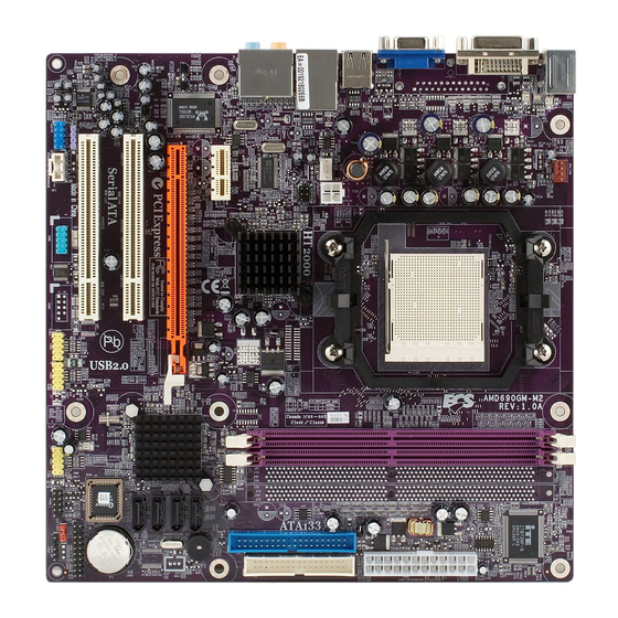
Page 10: Motherboard Components
Motherboard Components Introducing the Motherboard... - Page 11 Table of Motherboard Components LABEL COMPONENTS ™ Socket AM2 for AMD Athlon 64 X2 Dual-Core/ 1.CPU Socket ™ ™ Althlon 64/Sempron processors 240-pin DDR2 SDRAM slots 2.DIMM1~2 Standard 24-pin ATX power connector 3.ATX_POWER Floppy disk drive connector 4.FDD 5.IDE1 Primary IDE connector Wake On LAN Connector 6.WOL1* Serial ATA connectors...
- Page 12 Memo Introducing the Motherboard...
-
Page 13: Installing The Motherboard
Chapter 2 Installing the Motherboard Safety Precautions • Follow these safety precautions when installing the motherboard • Wear a grounding strap attached to a grounded device to avoid dam- age from static electricity • Discharge static electricity by touching the metal case of a safely grounded object before working on the motherboard •... -
Page 14: Checking Jumper Settings
Do not over-tighten the screws as this can stress the motherboard. Checking Jumper Settings This section explains how to set jumpers for correct configuration of the motherboard. Setting Jumpers Use the motherboard jumpers to set system configuration options. Jumpers with more than one pin are numbered. -
Page 15: Checking Jumper Settings
Checking Jumper Settings The following illustration shows the location of the motherboard jumpers. Pin 1 is labeled. Jumper Settings Type Jumper Description Setting (default) 1-2: NORMAL 2-3: CLEAR CMOS CLR_CMOS 3-pin CLEAR CMOS Before clearing the CLR_CMOS CMOS, make sure to turn off the system. -
Page 16: Connecting Case Components
Connecting Case Components After you have installed the motherboard into a case, you can begin connecting the motherboard components. Refer to the following: Connect the CPU cooling fan cable to CPU_FAN. Connect the system cooling fan connector to SYS_FAN. Connect the case switches and indicator LEDs to the PANEL1. Connect the standard power supply connector to ATX_POWER. -
Page 17: Fan Power Connectors
CPU_FAN/SYS_FAN: FAN Power Connectors Signal Name Function System Ground +12V Power +12V Sense Sensor CPU FAN control Users please note that the fan connector supports the CPU cooling fan of 1.1A~2.2A (26.4W max.) at +12V. ATX12V: ATX 12V Power Connector Signal Name Ground Ground... -
Page 18: Front Panel Connector
Front Panel Header The front panel header (PANEL1) provides a standard set of switch and LED con- nectors commonly found on ATX or Micro-ATX cases. Refer to the table below for information: Signal Function Signal Function HD_LED_P Hard disk LED(+) FP PWR/SLP *MSG LED(+) HD_LED_N Hard disk LED(-) FP PWR/SLP *MSG LED(-) -
Page 19: Installing Hardware
Installing Hardware Installing the Processor Caution: When installing a CPU heatsink and cooling fan make sure that you DO NOT scratch the motherboard or any of the surface- mount resistors with the clip of the cooling fan. If the clip of the cooling fan scrapes across the motherboard, you may cause serious damage to the motherboard or its components. -
Page 20: Cpu Installation Procedure
CPU Installation Procedure The following illustration shows CPU installation components. Install your CPU. Pull up the lever away from the socket and lift up to 90-degree angle. Locate the CPU cut edge (the corner with the pin hold noticeably missing). Align and insert the CPU correctly. -
Page 21: Installing Memory Modules
Installing Memory Modules This motherboard accommodates two or four memory modules. It can support two or four 240-pin unbuffered DIMMs, DDR2 800/667/533/400. The maximum memory capacity is 16 GB/32 GB. DDR2 SDRAM memory module table Memory module Memory Bus DDR2 400 200 MHz DDR2 533 266 MHz... - Page 22 Table A: DDR2 (memory module) QVL (Qualified Vendor List) The following DDR2 memory modules have been tested and qualified for use with this motherboard. Type Size Vendor Module Name K4T51163QB-ZCCC Samsung 256 MB DDR2 400 K4T51083QB-GCCC Samsung 512 MB Samsung K4T51083QB-GCCC Twinmos Corsair 4PB11D9CHM...
- Page 23 Table B: Unbuffered DIMM Address Timings and Drive Strength for AM2 Packge DRAM DIMM1 DIMM2 Timing Mode Speed DDR2-400 DDR2-400 DDR2-533 SRx16 SRx16 DDR2-533 SRx16 SRx8 SRx8 SRx16 DDR2-533 SRx8 SRx8 DDR2-533 DRx8 DRx8 DDR2-533 DRx8 SRx16 SRx16 DRx8 DDR2-533 DRx8 SRx8 SRx8...
-
Page 24: Installing A Hard Disk Drive/Cd-Rom/Sata Hard Drive
Installing a Hard Disk Drive/CD-ROM/SATA Hard Drive This section describes how to install IDE devices such as a hard disk drive and a CD- ROM drive. About IDE Devices Your motherboard has one IDE channel interface. An IDE ribbon cable supporting two IDE devices is bundled with the motherboard. -
Page 25: Installing A Floppy Diskette Drive
Refer to the illustration below for proper installation: Attach either cable end to the connector on the motherboard. Attach the other cable end to the SATA hard drive. Attach the SATA power cable to the SATA hard drive and connect the other end to the power supply. -
Page 26: Installing Add-On Cards
Installing Add-on Cards The slots on this motherboard are designed to hold expansion cards and connect them to the system bus. Expansion slots are a means of adding or enhancing the motherboard’s features and capabilities. With these efficient facilities, you can in- crease the motherboard’s capabilities by adding hardware that performs tasks that are not part of the basic system. - Page 27 Follow these instructions to install an add-on card: Remove a blanking plate from the system case corresponding to the slot you are going to use. Install the edge connector of the add-on card into the expansion slot. Ensure that the edge connector is correctly seated in the slot. Secure the metal bracket of the card to the system case with a screw.
-
Page 28: Connecting Optional Devices
Connecting Optional Devices Refer to the following for information on connecting the motherboard’s optional devices: AUDIO1: Front Panel Audio header This header allows the user to install auxiliary front-oriented microphone, line-in and line-out ports for easier access. Signal Name Signal Name PORT 1L AUD_GND PORT 1R... - Page 29 USB3~5: Front Panel USB headers The motherboard has four USB ports installed on the rear edge I/O port array. Additionally, some computer cases have USB ports at the front of the case. If you have this kind of case, use auxiliary USB connector to connect the front-mounted ports to the motherboard.
- Page 30 SATA1~4: Serial ATA connectors These connectors are used to support the new Serial ATA devices for the highest date transfer rates (3.0 Gb/s), simpler disk drive cabling and easier PC assembly. It elimi- nates limitations of the current Parallel ATA interface. But maintains register com- patibility and software compatibility with Parallel ATA.
- Page 31 JLPC1: TPM header Pin No. Symbol Pin No. Symbol CLK_33MHz L_FRAME# PCIRST # L_AD3 L_AD2 VCC3 L_AD1 L_AD0 SM_CLK SM_DAT 3VSB SERIRQ CLKRUN# L_PCPD# Installing the Motherboard...
-
Page 32: Connecting I/O Devices
Connecting I/O Devices The backplane of the motherboard has the following I/O ports: PS2 Mouse Use the upper PS/2 port to connect a PS/2 pointing device. PS2 Keyboard Use the lower PS/2 port to connect a PS/2 keyboard. Parallel Port (LPT) Use LPT to connect printers or other parallel communica (Optional) tions devices. -
Page 33: Using Bios
Chapter 3 Using BIOS About the Setup Utility The computer uses the latest Award BIOS with support for Windows Plug and Play. The CMOS chip on the motherboard contains the ROM setup instructions for con- figuring the motherboard BIOS. The BIOS (Basic Input and Output System) Setup Utility displays the system’s configuration status and provides you with options to set system parameters. -
Page 34: Bios Navigation Keys
Press DEL to enter SETUP Pressing the delete key accesses the BIOS Setup Utility: Phoenix-Award WorkstationBIOS CMOS Setup Utility: Standard CMOS Features Frequency/Voltage Control Advanced BIOS Features Load Fail-Safe Defaults Advanced Chipset Features Load Optimized Defaults Integrated Peripherals Set Supervisor Password Power Management Setup Set User Password PnP/PCI Configurations... -
Page 35: Updating The Bios
Updating the BIOS You can download and install updated BIOS for this motherboard from the manufacturer’s Web site. New BIOS provides support for new peripherals, improve- ments in performance, or fixes for known bugs. Install new BIOS as follows: If your motherboard has a BIOS protection jumper, change the setting to allow BIOS flashing. -
Page 36: Standard Cmos Features
Standard CMOS Features This option displays basic information about your system. Phoenix-Award WorkstationBIOS CMOS Setup Utility Standard CMOS Features Date (mm:dd:yy) Sun, Jan 1 2006 Item Help Time (hh:mm:ss) 21 : 48 : 55 Menu Level IDE Channel 0 Master [None] Change the day, month, IDE Channel 0 Slave... - Page 37 IDE Channel 0 Master (Auto) Leave this item at Auto to enable the system to automatically detect and configure IDE devices on the channel. If it fails to find a device, change the value to Manual and then manually configure the drive by entering the characteristics of the drive in the items described below.
-
Page 38: Advanced Bios Features
Advanced BIOS Features This option defines advanced information about your system. Phoenix-Award WorkstationBIOS CMOS Setup Utility Advanced BIOS Features ATA 66/100 IDE Cable Msg [Enabled] Item Help Removabled Device Priority [Press Enter] Hard Disk Boot Priority [Press Enter] Menu Level Network Boot Priority [Press Enter] CPU Internal Cache... - Page 39 Hard Disk Boot Priority (Press Enter) Scroll to this item and press <Enter> to view the following screen: Phoenix-Award WorkstationBIOS CMOS Setup Utility Hard Disk Boot Priority 1. Bootable Add-in Cards Item Help Menu Level Use < > or < >...
- Page 40 First/Second/Third Boot Device (Hard Disk/Hard Disk/CDROM) Use these three items to select the priority and order of the devices that your system searches for an operating system at start-up time. Boot Other Device (Enabled) When enabled, the system searches all other possible locations for an operating system if it fails to find one in the devices specified under the First, Second, and Third boot devices.
-
Page 41: Advanced Chipset Features
Advanced Chipset Features These items define critical timing parameters of the motherboard. You should leave the items on this page at their default values unless you are very familiar with the technical specifications of your system hardware. If you change the values incor- rectly, you may introduce fatal errors or recurring instability into your system. - Page 42 Timing Mode (Auto) This item allows you to set up the DRAM timing manually or automatically. Memory Clock value or Limi (DDR2 400) When DDR2 Timing Setting by is set to Manual, use this item to set the DRAM frequency. SPD Checksum Restart (Ignore) This item enables or disables SPD Checksum Restart function.
- Page 43 LDT & PCI Bus Control (Press Enter) Scroll to this item and press <Enter> to view the following screen: Phoenix-Award WorkstationBIOS CMOS Setup Utility LDT &PCI Bus Control LDT Configuration [Enabled] Item Help Upstream LDT Bus Width [16 bit] Menu Level Downstream LDT Bus Width [16 bit] LDT Bus Frequency...
-
Page 44: Integrated Peripherals
AGP Aperture Size (128 MB) This item allows users to manually adjust the AGP aperture size, from 32 MB to 2 GB. GFX Clock Mode (Sync) This item allows users to set the GFX Clock Mode to be Sync or Async. When this item is set to Sync, the following 3 item is activated. - Page 45 South OnChip IDE Device (Press Enter) Scroll to this item and press <Enter> to view the following screen: Phoenix-Award WorkstationBIOS CMOS Setup Utility South OnChip IDE Device Item Help IDE DMA transfer access [Enabled] Onchip IDE Channel0 [Enabled] Menu Level Primary Master PIO [Auto] Primary Slave PIO...
- Page 46 South OnChip PCI Device (Press Enter) Scroll to this item and press <Enter> to view the following screen: Phoenix-Award WorkstationBIOS CMOS Setup Utility South OnChip PCI Device Item Help ATI Azalia Audio [Auto] ATI SATA Controller [Enabled] Menu Level ATI SATA Type [Native IDE] SB600 Spread Spectrum [Disabled]...
- Page 47 SuperIO Device (Press Enter) Scroll to this item and press <Enter> to view the following screen: Phoenix-Award WorkstationBIOS CMOS Setup Utility SuperIO Device Item Help Onboard FDC Controller [Enabled] Onboard Serial Port 1 [3F8/IRQ4] Menu Level Onboard Parallel Port [378/IRQ7] Parallel Port Mode [ECP] ECP Mode Use DMA...
-
Page 48: Power Management Setup
LAN Boot ROM (Disabled) Use this item to enable and disable the booting from the onboard LAN or a network add-in card with a remote boot ROM installed. 1. When too many expansion cards occupy the memory size of shadow ram, or the RAID Mode enabled, the function of LAN Boot ROM may not function normally. - Page 49 Soft-Off by PWRBTN (Instant Off) Under ACPI (Advanced Configuration and Power management Interface) you can create a software power down. In a software power down, the system can be resumed by Wake Up Alarms. This item lets you install a software power down that is con- trolled by the power button on your system.
-
Page 50: Pnp/Pci Configurations
Resume By PS2 MS (S3) (Disabled) This option enables or disables you to allow mouse activity to awaken the system from power saving mode. Resume By PS2 KB (S3) (Disabled) This option enables or disables you to allow keyboard activity to awaken the system from power saving mode. -
Page 51: Pc Health Status
If you cannot get a legacy ISA (Industry Standard Architecture) expansion card to work properly, you might be able to solve the problem by changing this item to Manual, and then opening up the IRQ Resources submenu. • IRQ Resources (Press Enter): In the IRQ Resources submenu, if you assign an IRQ to Legacy ISA, then that Interrupt Request Line is reserved for a legacy ISA expansion card. -
Page 52: Frequency/Voltage Control
SMART Fan Control (Auto) Press Ctrl + F1 to show this item. This item allows you to enable/disable the control of the system fan speed by changing the fan voltage. FAN1 START PWM VALUE (63) Press Ctrl + F1 to show this item. This item displays the PWM value smart fan starts. -
Page 53: Load Fail-Safe Settings
NPT Fid controller (Auto) This item allows users to adjust the CPU frequency; the range will be varied according to different CPUs. We strongly recommend you leave this item at its default value. NPTVid controller (Auto) This item allows users to adjust the CPU voltage .We strongly recommend you leave this item at its default value. -
Page 54: Set Supervisor/User Password
Set Supervisor/User Password When this function is selected, the following message appears at the center of the screen to assist you in creating a password. ENTER PASSWORD Type the password, up to eight characters, and press <Enter>. The password typed now will clear any previously entered password from CMOS memory. You will be asked to confirm the password. -
Page 55: Using The Motherboard Software
Chapter 4 Using the Motherboard Software About the Software CD-ROM The support software CD-ROM that is included in the motherboard package contains all the drivers and utility programs needed to properly run the bundled products. Below you can find a brief description of each software program, and the location for your motherboard version. -
Page 56: Running Setup
Setup Tab Setup Click the Setup button to run the software installation program. Select from the menu which software you want to install. Browse CD The Browse CD button is the standard Windows command that allows you to open Windows Explorer and show the contents of the support CD. - Page 57 Click Next. The following screen appears: Check the box next to the items you want to install. The default options are recom- mended. Click Next run the Installation Wizard. An item installation screen appears: Follow the instructions on the screen to install the items. 1.
- Page 58 Method 1. Run Reboot Setup Windows Vista will block startup programs by default when installing drivers after the system restart. You must select taskbar icon Run Blocked Program and run Reboot Setup to install the next driver, until you finish all drivers installation. Method 2.
- Page 59 Select Classic View. Set User Account. Select Turn User Account Control on or off and press Continue. Using the Motherboard Software...
-
Page 60: Manual Installation
Disable User Account Control (UAC) to help protect your computer item and press OK, then press Restart Now. Then you can restart your computer and continue to install drivers without running blocked programs. Manual Installation Insert the CD in the CD-ROM drive and locate the PATH.DOC file in the root directory. -
Page 61: Setting Up Amd Sb600 Raid Configuration
Chapter 5 Setting Up AMD SB600 RAID Configuration Setting Up a bootable RAID Array This section explains how to configure a bootable AMD RAID array. Setting Up the BIOS Start your computer, then press Delete to enter the BIOS setup. The BIOS CMOS Setup Utility screen appears. - Page 62 The South Onchip IDE Device window appears. Figure 1.3 South Onchip IDE Device Screen From the South Onchip IDE Device window, globally set ATI SATA Type to RAID. Press F10 to save the configuration and exit. The PC reboots. Enter the RAID BIOS Setup by pressing Ctrl-F when prompted, and proceed to set up the AMD RAID BIOS as described in the next section.
- Page 63 The Main Menu screen appears (Figure 1.4). Figure 1.4 Main Menu Select [2], then select LD 1 in the following page. The Define LD Menu screen appears (Figure 1.5). Figure 1.5 Define LD Menu Using the Define a New Array Screen If necessary, press the tab key to move from field to field until the appropriate field is highlighted.
- Page 64 • Selecting the Stripe Block Size Stripe block size is given in kilobytes, and affects how data is arranged on the disk. It is recommended to leave this value at the default Optimal, which is 64KB, but the values can be 64 KB and 128 KB. When choose RAID 1, the Stripe block size is unchangable.
- Page 65 Press ESC to exit. The Main Menu screen appears (Figure 1.8). Figure 1.8 Main Menu Press Y to reboot. The following screen appears (Figure 1.9). Figure 1.9 AMD RAID Configuration...
- Page 66 Installing the RAID Drivers Your system may come with a Windows install CD that already includes AMD RAID drivers. If so, then this section is not relevant. If that is not the case (or you are trying to install a new version of Windows), then you will need an AMD RAID driver F6 install floppy.
- Page 67 The following Windows Setup screen appears: Figure 1.12 Windows Setup—Selected SCSI Adapter Select “ATI AHCI Compatible RAID Controller-x86 platform” and press Enter for 32-bit OS or Select “ATI AHCI Compatible RAID Controller-x64 platform” and press Enter for 64-bit OS. The following Windows Setup screen appears listing both drivers:. Figure 1.13 Windows Setup—AMD drives listed Press Enter to continue with Windows XP Installation.
- Page 68 Memo AMD RAID Configuration...
Need help?
Do you have a question about the AMD690GM-M2 and is the answer not in the manual?
Questions and answers