Table of Contents
Advertisement
Quick Links
Instruction Manual
D100307X012
r
Fisher
657 Diaphragm Actuators
Size 80 and 100
Contents
. . . . . . . . . . . . . . . . . . . . . . . . . . . . . . . . .
. . . . . . . . . . . . . . . . . . . . . . . . . . . . .
. . . . . . . . . . . . . . . . . . . . . . . . . . . . . . . . .
. . . . . . . . . . . . . . . . . . . . . . . . . . . . . . .
. . . . . . . . . . . . . . . . . . . . . . . . . . . . . . . . . . .
. . . . . . . . . . . . . . . . . . . . . . . . . . .
. . . . . . . . . . . . . . . . . . . . . . . . . . . . . . . . .
. . . . . . . . . . . . . . . . . . . . . . . . . . . . . . . . . . . . . .
. . . . . . . . . . . . . . . . . . . . . . . . . . . . . . . . . . . . .
. . . . . . . . . . . . . . . . . . . . . . . . . . . . . . . . .
. . . . . . . . . . . . . . . . . . . . . . . . . . . . . . . .
. . . . . . . . . . . . . . . . . . . . . . . . . . . . . . . . .
. . . . . . . . . . . . . . . . . . . . . . . . . . . . . . . . . . .
. . . . . . . . . . . . . . . . . . . . . . . . .
. . . . . . . . . . . . . . . . . . . . . . . . . . . .
. . . . . . . . . . . . . . . . . . . . . . . . . . . . . .
. . . . . . . . . . . . . . . . . . . . . . . . . . . .
. . . . . . . . . . . . . . . . . . . . . . . . . . . . . .
(Adjustable Up Travel Stop)
. . . . . . . . . . . . . . . . . . . . . . . . . . . .
Introduction
Scope of Manual
This instruction manual provides information on installation, adjustment, maintenance, and parts ordering for the
Fisher 657 actuator in sizes 80 and 100. Refer to separate instruction manuals for information about other equipment
and accessories used with these actuators.
Do not install, operate, or maintain 657 actuators without being fully trained and qualified in valve, actuator, and
accessory installation, operation, and maintenance. To avoid personal injury or property damage, it is important to
carefully read, understand, and follow all the contents of this manual, including all safety cautions and warnings. If you
have any questions about these instructions, contact your Emerson Process Management sales office before
proceeding.
www.Fisher.com
. . . . . . . . . . . . . . . . . . . . . .
. . . . . . . . . . . . . . . . . . . . . .
. . . . . . . . . . . . . . . . . . . .
. . . . . . . . . . . . . . . . . . . . . . .
. . . . . . . . . . . . .
. . . . . . . . . . . . . . . . . . . .
. . . . . . . . . . . . . . . .
. . . . . . . . . . . . . . . .
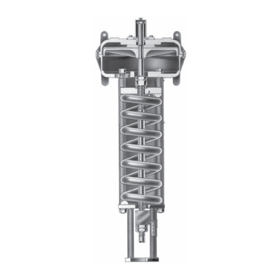
Figure 1. Sectional view of Fisher 657
Size 100 Actuator
1
1
2
3
3
3
4
4
4
5
5
5
7
7
7
8
10
11
12
12
13
13
W0366-1
13
14
14
14
15
. . . . . . . . . . . . . . . . . . . . . . . . . . . . . . . . . . .
657 Size 80 and 100 Actuators
. . . . . . . . . . . . . . . . . . . . . . . . . . . . . .
. . . . . . . . . . . . . . . . . . . . . . . . . . . . . . .
December 2010
15
15
16
Advertisement
Table of Contents

Related Manuals for Fisher 657


Summary of Contents for Fisher 657
-
Page 1: Table Of Contents
Scope of Manual This instruction manual provides information on installation, adjustment, maintenance, and parts ordering for the Fisher 657 actuator in sizes 80 and 100. Refer to separate instruction manuals for information about other equipment and accessories used with these actuators. -
Page 2: Description
Figure 2 shows the operation of these actuators. A 657 actuator can be furnished with either a top‐mounted or side‐mounted (size 80 only) handwheel assembly. A top‐mounted handwheel assembly is normally used as an adjustable‐up travel stop. The size 100 top‐mounted... -
Page 3: Specifications
A side‐mounted handwheel assembly is normally used as an auxiliary manual actuator. Specifications Refer to table 1 for specifications of the 657 actuator. See the actuator nameplate for information about a specific actuator. Maximum Pressure Limitations The casing and diaphragm of 657 actuators are pressure operated. -
Page 4: Loading Connection
657 Size 80 and 100 Actuators December 2010 2. Screw valve stem locknuts (key 16, figure 4) all the way onto valve stem thread. 3. Connect an air supply to the diaphragm casing. 4. For push‐down‐to‐close valves, be sure the valve plug is on its seat. Apply pressure to ensure that the actuator stem is fully extended. -
Page 5: Spring
The actuator must be in the vertical position when adjusting spring to avoid damage to thrust bearing (key 35, figure 5) and to properly position spacers required for adjustment. Remove the shroud plate (key 107, figure 5), and loosen the jam nut (key 115, figure 5). 657 Size 80 and 100 Actuators December 2010... - Page 6 657 Size 80 and 100 Actuators December 2010 Figure 3. Dimension B for Spring Adjustment ADJUSTING NUT A0950‐1 For small spring forces, adjustments can be made by rotating the adjusting nut (key 114, figure 5). Clockwise rotation (when viewed from diaphragm casings) of the adjusting nut will increase the loading pressure required to start actuator stem travel, and counterclockwise rotation will decrease the pressure required to start travel.
-
Page 7: Maintenance
Key numbers refer to figure 4 for size 80 actuators and figure 5 for size 100 actuators. Size 80 Disassembly 1. Bypass the control valve. Reduce the loading pressure to atmospheric, and remove the tubing or piping from the top of the diaphragm casing (key 1). 657 Size 80 and 100 Actuators December 2010... -
Page 8: Size 80 Assembly
657 Size 80 and 100 Actuators December 2010 WARNING To avoid personal injury from the precompressed spring force thrusting the upper diaphragm casing (key 1) away from the actuator, relieve spring compression (step 2, below), and carefully remove casing cap screws (key 22) (step 4, below). - Page 9 9. Repeat this procedure by tightening four hex nuts, diametrically opposed and 90 degrees apart, to the final torque value that is specified in table 2 for the diaphragm material being used. 657 Size 80 and 100 Actuators INITIAL TORQUE...
-
Page 10: Size 100 Disassembly
657 Size 80 and 100 Actuators December 2010 10. Tighten the remaining hex nuts in a clockwise, criss‐cross pattern to the final torque value that is specified in table 2 for the diaphragm material being used. 11. After the last hex nut is tightened complete another tightening sequence, this time in a circular pattern around the bolt circle to the final torque value that is specified in table 2 for the diaphragm material being used. -
Page 11: Size 100 Assembly
When you replace actuator diaphragms in the field, take care to ensure the diaphragm casing bolts are tightened to the proper load to prevent leakage, but not crush the material. Perform the following tightening sequence with a manual torque wrench for size 80 and 100 actuators. 657 Size 80 and 100 Actuators December 2010... -
Page 12: Size 80 Side-Mounted Handwheel
657 Size 80 and 100 Actuators December 2010 CAUTION Over‐tightening the diaphragm casing cap screws and nuts can damage the diaphragm. Do not exceed 68 NSm (50 lbfSft) torque. Note Do not use lubricant on these bolts and nuts. Fasteners must be clean and dry. -
Page 13: Assembly
Size 80 Hydraulic Snubber The size 80 657 is available with a hydraulic snubber, as shown in figure 7, to dampen vertical instability of actuator stem movement. The snubber is adjusted by rotating the adjusting screws (key 83, figure 7) counterclockwise out of the reservoir (key 79, figure 7) to increase damping action and clockwise to decrease damping action. -
Page 14: Disassembly
657 Size 80 and 100 Actuators December 2010 The actuator should be equipped with a side‐mounted handwheel, which is designed for more frequent use as a manual operator. A top‐mounted handwheel assembly is normally used as an adjustable‐up travel stop to limit full retraction of the actuator stem. -
Page 15: Size 100 Top-Mounted Handwheel Assembly
Each actuator has a serial number stamped on the nameplate. Always refer to this number when corresponding with your Emerson Process Management sales office regarding replacement parts or technical information. Also, always refer to the 11‐character part number of each needed part as found in the following parts list. 657 Size 80 and 100 Actuators December 2010... -
Page 16: Parts List
Use only genuine Fisher replacement parts. Components that are not supplied by Emerson Process Management should not, under any circumstances, be used in any Fisher valve, because they may void your warranty, might adversely affect the performance of the valve, and could cause personal injury and property damage. -
Page 17: D100307X012 December
Instruction Manual 657 Size 80 and 100 Actuators D100307X012 December 2010 Figure 4. Size 80 Fisher 657 Actuator APPLY LUB 40A8771‐B... - Page 18 657 Size 80 and 100 Actuators December 2010 Figure 5. Size 100 Fisher 657 Actuator APPLY LUB 50A2621‐F Instruction Manual D100307X012...
- Page 19 25,000 787.9 36,000 1050.6 45,000 58.6 2480 175.1 5630 288.9 7900 367.7 10,600 455.2 10,600 542.8 13,800 657 Size 80 and 100 Actuators PART NUMBER 1J518227082 1H747727082 1H747527082 1H747327082 1H747627082 1H747027082 PART NUMBER 77,840 10A2561X012 111,200 10A2562X012 160,128 10A2563X012 200,160...
-
Page 20: Size 80 Side-Mtd Handwheel
657 Size 80 and 100 Actuators December 2010 Size 80 Side‐Mtd Handwheel Description 7 Travel Stop 17 Machine Screw 28 Machine Screw 40 Set Screw 41 Set Screw 44 Worm Gear 45 Worm Shaft 46 Lower Sleeve 47 48 Front Worm Retainer 49 ... - Page 21 Instruction Manual 657 Size 80 and 100 Actuators D100307X012 December 2010 Figure 7. Size 80 Fisher 657 Actuator with Side‐Mounted Handwheel and Hydraulic Snubber SECTION B‐B VIEW A VIEW A SECTION C‐C APPLY LUB 50A8774‐C...
- Page 22 657 Size 80 and 100 Actuators December 2010 Figure 8. Top‐Mounted Handwheel for Size 100 Actuator APPLY LUB 50A2622‐F SECTION A‐A Instruction Manual D100307X012...
- Page 23 Instruction Manual 657 Size 80 and 100 Actuators D100307X012 December 2010...
- Page 24 December 2010 Fisher is a mark owned by one of the companies in the Emerson Process Management business division of Emerson Electric Co. Emerson Process Management, Emerson, and the Emerson logo are trademarks and service marks of Emerson Electric Co. All other marks are the property of their respective owners.
Need help?
Do you have a question about the 657 and is the answer not in the manual?
Questions and answers