
Related Manuals for HAMPTON BAY Altura


Summary of Contents for HAMPTON BAY Altura
-
Page 1: Ceiling Fan
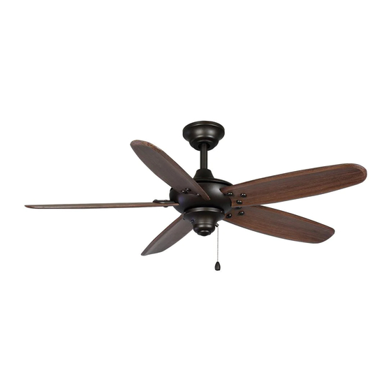
Altura Ceiling Fan Owner’s Manual Altura Ventilador de Techo de 1,72 Manual del Propietario UL model no: 68-ATR... -
Page 2: Table Of Contents
68” Altura Thank you for purchasing this Hampton Bay ceiling fan. This product has been manufactured with the highest standards of safety and quality. The finish Ceiling Fan by Hampton Bay of this fan is weather resistant, but over time will naturally weather and fade. -
Page 3: Safety Rules 1
READ AND SAVE THESE INSTRUCTIONS To avoid personal injury or damage to the fan and To reduce the risk of electric shock, insure electricity other items, be cautious when working around or has been turned off at the circuit breaker or fuse box cleaning the fan. -
Page 4: Parts View
Unpack your fan and check the contents. You should have the following items: Blade attachment hardware Mounting Plate (inside canopy) Switch Box Adaptor (15 screws, 15 decorative screws) Downrod and Ball Assembly Switch Box Mounting & Electrical Hardware Canopy Hand Unit/Receiver (1 hanger pin, 1 locking pin, Decorative Motor Collar Cover 3 plastic wire connectors) -
Page 5: Installing Your Fan 3
Figure 4 TURES ARE NOT ACEPTABLE FOR SUPPORT- ING A FAN, AND MAY NEED TO BE REPLACED. (available at your Hampton Bay retailer). CONSULT A QUALIFIED, LICENSED ELECTRI- CIAN FOR EXACT SPECIFICATIONS. Installing Your Fan 3. -
Page 6: Standard Ceiling Mounting
Hanging the Fan Align the holes at the bottom of the non-slotted screws and loosen the slotted downrod with the holes in the collar screws. This will enable you to remove the REMEMBER on top of the motor housing (Figure 7). turn pow- mounting plate (Figure 6). -
Page 7: Installing To Outlet Box
installed by a licensed electrician. Install the ceiling mounting plate on the out- let box, by sliding the mounting plate over Motor Wires Follow the steps below to connect the fan the two screws provided with the outlet box to your household wiring. Use the wire Ball/Downrod (Figure 8). -
Page 8: Setting The Code
EACH WIRE NUT (WIRE CONNECTOR) SUP- THE FREQUENCIES ON YOUR RECEIVER AND PLIED WITH THIS FAN IS DESIGNED TO ACCEPT TRANSMITTER HAVE BEEN PRESET AT THE UP TO ONE 12 GAUGE HOUSE WIRE AND TWO FACTORY. BEFORE INSTALLING THE RECEIV- WIRES FROM THIS FAN. -
Page 9: Blade Balancing
Attaching the Blade Balancing Fan Blades All blades are grouped by weight. Because nat- ural woods vary in density, the fan may wobble Attach blade to blade arm using decorative even though the blades are weight matched. screws and screws as shown in Figure 10. The following procedure should correct most Start a screw into decorative screws. -
Page 10: Installing Switch Box
Installing the Align the key hole slots in the switch box adaptor with the two serrated head screws in Switch Box the black bracket. Turn the switch box adaptor clockwise until CAUTION - To reduce the risk of electrical the two serrated head screws are situated in shock, disconnect the electrical supply circuit to the narrow end of the keyholes. -
Page 11: Forward/Reverse
Remote Control - Your fan is equipped with a remote control to operate the speed and lights of your new ceiling fan. For more information on how to install the remote control, see the re- mote control instruction along with the remote Warm weather - (Forward) A downward control components. -
Page 12: Operating Your Remote
Remote Control Transmitter Operation Your fan is equipped with a remote control NOTE: This remote is equipped with 16 code combinations. To prevent possible interference to operate the speed and lights of your new from or to other remote units such as garage ceiling fan. -
Page 13: Care Of Your Fan
Troubleshooting Care of Your Fan Here are some suggestions to help you Problem Solution maintain your fan. Fan will not start Check main and branch circuit fuses or breakers Because of the fan’s natural movement, Check line wire connections to the fan and switch wire connections in some connections may become loose. -
Page 14: Specifications 12
FAN POWER AIRFLOW EFFICIENCY AIRFLOW CONSUMPTION FAN SIZE SPEED VOLTS (HIGHER IS BETTER) N.W. G.W. C.F. (WITHOUT CFM/WATT LIGHTS) WATT 3780 33.9 37.8 68” 5453 3.34 High 8752 These are approximate measures. They do not include Amps and Wattage used by the light kit. Distributed by Home Depot U.S.A., Inc. -
Page 15: Warranty Information 13
You must present a copy of the original Hampton Bay also warrants that all other fan parts, excluding any glass or acrylic blades, to be free purchase receipt to obtain warranty service.
Need help?
Do you have a question about the Altura and is the answer not in the manual?
Questions and answers