Table of Contents
Advertisement
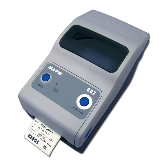
CG208DT
CG212DT
Direct Thermal Type
203 dpi/ 305 dpi
Read this Operator Manual before and during usage of the above product.
Keep this document handy for future reference.
Operator Manual
CG208TT
CG212TT
Thermal Transfer Type
203 dpi/ 305 dpi
www.satoamerica.com
For printer model:
CG2 Series
PN: 9001211B
Advertisement
Table of Contents
Troubleshooting

Related Manuals for SATO CG2 Series


Summary of Contents for SATO CG2 Series
- Page 1 Operator Manual For printer model: CG2 Series CG208DT CG208TT CG212DT CG212TT Direct Thermal Type Thermal Transfer Type 203 dpi/ 305 dpi 203 dpi/ 305 dpi PN: 9001211B Read this Operator Manual before and during usage of the above product. Keep this document handy for future reference.
- Page 2 SATO Corporation reserves the right to change or improve this product and document without notice. Trademarks SATO is a registered trademark of SATO Corporation and/or its subsidiaries in Japan, the U.S and other countries. SATO America, Inc.
- Page 3 If the fluid is drunk, voltage tion could cause a fire or electric immediately consult with a physi- • Do not use other than the specified shock. cian. voltage. Doing so could result in fire or electric shock. CG2 Series Operator Manual Page i...
- Page 4 • Do not operate the power result in injury. Be careful not to switch or plug in/unplug the become injured when replacing power cord with wet hands. paper or cleaning. Doing so could result in electric shock. Page ii CG2 Series Operator Manual...
-
Page 5: Power Supply
Precautions for Installation and Handling Printer operation can be affected by the printer environment. Refer to the following instructions for installation and handling of CG2 Series printer. Select a Safe Location Place the printer on a surface that is flat and level. - Page 6 Safety Precautions Page iv CG2 Series Operator Manual...
-
Page 7: Table Of Contents
5.5 Adjusting Print Quality ....................5 - 6 General Specifications ..................... 6 - 1 6.1 Printer Basic Specifications..................6 - 1 6.2 Optional Accessories Specifications ................6 - 7 Interface Specifications.................... 7 - 1 CG2 Series Operator Manual Page v... - Page 8 8.7 Offset position Adjustment ..................8 - 12 8.8 Paper End ........................8 - 13 8.9 Ribbon End ........................ 8 - 14 SATO Group of Companies ..................9 - 1 SATO Group of Companies ....................9 - 2 Page vi...
-
Page 9: Introduction
1.1 FEATURES OF THE PRINTER The CG2 Series is 2 inch Compact Desktop printer (Thermal Transfer or Direct Thermal). With a 32-bit RISC CPU, 4 ips print speed, and 4MB Flash Memory, the CG2 Series is an economical printer with numerous features making it suitable for a wide range of applications. -
Page 10: Unpacking
4. Set the printer on a solid, flat surface. Inspect the shipping container and printer for any sign of damage that may have occurred during shipping. Please note that SATO shall hold no liability of any damage of any kind sustained during shipping of the product. -
Page 11: Parts Identification
Opening for media output. VR3 potentiometer (Offset/ Pitch) This potentiometer adjusts the option (Cutter, Dispenser, Tear-off) stop position (offset position). Pitch position adjustment is also available in the Pitch adjustment VR mode of Factory Adjustment mode. CG2 Series Operator Manual Page 1-3... - Page 12 Or, to connect the optional wireless LAN interface unit to the printer (This applies only to the Type 1 board). VR2 potentiometer (I-Mark) This potentiometer is used to adjust the sensing level of the I-Mark sensor. Page 1-4 CG2 Series Operator Manual...
- Page 13 This roller feeds the paper. Perform Roll media holder maintenance at regular intervals. To hold the roll media. Media guide slide lever Set to meet the size of the media used. CG2 Series Operator Manual Page 1-5...
- Page 14 Section 1: Introduction This page is intentionally left blank Page 1-6 CG2 Series Operator Manual...
-
Page 15: Installation
The following information is provided: • 2.1 Site Location • 2.2 Media Selection • 2.3 Loading Labels or Tags • 2.4 Loading the Carbon Ribbon (For CG208TT, CG212TT only) • 2.5 Connections CG2 Series Operator Manual Page 2-1... -
Page 16: Site Location
For optimal print performance and durability, please use SATO-certified label and ribbon supplies on this printer. Using supplies not tested and approved for use by SATO can result in unnecessary wear and damage to vital parts of the printer, and may void the warranty. -
Page 17: Loading Labels Or Tags
Media guides Note: Make sure the printed side of the media is facing upwards. Printed side should face upwards CG2 Series Operator Manual Page 2-3... - Page 18 When replacing media, bear in mind that the print head and its surrounding area remain hot. Keep your fingers away from these areas to prevent injury. • Avoid touching even the edge of the print head with your bare hands. Page 2-4 CG2 Series Operator Manual...
- Page 19 • If the optional cutter or dispenser has been purchased, see Section 8.1 Optional Accessories - Cutter and Section 8.2 Optional Accessories - Dispenser on how to route the media. CG2 Series Operator Manual Page 2-5...
- Page 20 Avoid touching even the edge of the print head with your bare hands. 2.3.3 Overview of the Roll media and Fan-folded media loading path Roll media (Face-out) Fan-fold media Roll media (Face-in) (Printed side face up) Page 2-6 CG2 Series Operator Manual...
-
Page 21: Loading The Carbon Ribbon (For Cg208Tt, Cg212Tt Only)
Then simply let down the ribbon unit. There is a stopper midway through its movement range that will prevent the ribbon unit from snapping down. Lever Ribbon unit CG2 Series Operator Manual Page 2-7... - Page 22 . Turn the ribbon roll until the core snaps on the protrusion of the left ribbon supply unit. Note: Use only genuine SATO carbon ribbons for maximum groove print quality and printer durability. protrusion In Mount the empty ribbon core on the ribbon wind-up unit the same manner as in step 3 above.
- Page 23 When replacing carbon ribbon, bear in mind that the print head and its surrounding area remain hot. Keep your fingers away from these areas to prevent injury. • Avoid touching even the edge of the print head with your bare hands. CG2 Series Operator Manual Page 2-9...
-
Page 24: Connections
This section explains the power cable and interface cable connection procedures. 2.5.1 Standard interface connection CG2 Series printers have two types of Main PCBs, and each type of PCB is equipped with a different type of interface to perform data communication with the host. These are described as follows. - Page 25 2.5.2 Connecting the optional keypad The optional keypad can be connected to the RS-232C terminal of the Type 1, CG2 Series printer, thus providing a stand-alone feature. This feature enables users to enter simple commands flashes in red in long intervals for the printer, by the connected keypad, without connecting to a host computer.
- Page 26 Press and hold the POWER button until the ON LINE (POWER) indicator displays red and then turns off. If there is any printed paper remaining in the printer, cut it off. ON LINE (POWER) Page 2-12 CG2 Series Operator Manual...
-
Page 27: Operation And Configuration
Before using the printer, it is best to read this manual thoroughly. Otherwise, you may disturb default settings on which the instructional procedures in this manual are based. Most of the printer’s settings are controlled via standard SBPL commands or by using the provided SATO Utilities Tool application. -
Page 28: Operator Panel
Indicator: Solid red light. Example 2 Indicator: Solid green light. Example 3 Indicator: Blinking red light. Example 4 Indicator: Blinking green light. Example 5 Indicator: Blinking red & green light in turn Example 6 Indicator: off Page 3-2 CG2 Series Operator Manual... -
Page 29: Operating Modes
3.1 OPERATOR PANEL (cont’d) The CG2 Series printer has three potentiometers to change the printer settings. VR1 and VR2 potentiometers are located at the bottom back panel of the printer, while VR3 potentiometer is located at the bottom right of the front side. - Page 30 FEED/LINE button Wireless LAN Setting Print Mode* Blinking red light Holding FEED/LINE * Available only when connected button to Wireless LAN interface. ON LINE (POWER) indicator : Off : Red light : Green light Page 3-4 CG2 Series Operator Manual...
-
Page 31: User Test Print Mode
FEED/LINE button is press again. To terminate the User Test Print mode First, ensure that you have pressed the FEED/LINE button to pause the test printing, then press POWER to turn off the printer. CG2 Series Operator Manual Page 3-5... - Page 32 ON/ OFF Option waiting time Option waiting time ****ms Proto-codes Protocol code setting value Standard / Nonstandard (Standard / Nonstandard) Operation mode Operation mode CONTINUOUS TEAR OFF DISPENSER Head Check Head Check ON/ OFF Page 3-6 CG2 Series Operator Manual...
- Page 33 Multi Protocol Protocol Driver Interface 2 Interface 2(LAN) LAN Ver/Date LAN module **.** / YY.MM.DD F/W version, creation date Buffer Type Buffer type Multi Protocol Protocol Driver(CYC) Driver(ENQ) Status3 MAC Address MAC address **:**:**:**:**:** CG2 Series Operator Manual Page 3-7...
- Page 34 Ad hoc Infrastructure(SSID) SSID SSID 1~32-chr string Channel Channel 1~11 Security Mode Security type WPA2 DynamicWEP Interface 2 Interface 2(RS-232C) RS-232C Buffer Type Buffer type 1 item / Multi Protocol Protocol ER/RS XON/XOF Driver Status3 Page 3-8 CG2 Series Operator Manual...
-
Page 35: Factory Test Print Mode
FEED/LINE button is press again. To terminate the Factory Test Print mode First, ensure that you have pressed the FEED/LINE button to pause the test printing, then press POWER to turn off the printer. CG2 Series Operator Manual Page 3-9... - Page 36 ±45 DOT [305dpi] Option Offset[VR3] Option stop position ±30 DOT [203dpi] ±45 DOT [305dpi] FROM1 CHECK SUM Printer F/W: Font: Check (B)**** (P)**** (F)**** (A)**** LAN(WLAN) CHECK LAN(WLAN) F/W check sum (B)**** (P)**** (A)**** Page 3-10 CG2 Series Operator Manual...
-
Page 37: Operation Setting Mode
FEED/LINE button is held down.) Release FEED/LINE Printer enters Opera- button when ON LINE tion Setting Mode. Blinking green light (POWER) indicator changes to blinking green light. To be continued on the next page. CG2 Series Operator Manual Page 3-11... - Page 38 (NOTE: This step is NOT (For download mode selection, the printer will continue to complete required for download mode.) the downloading process. Refer to section 3.6 and 3.7 for details.) Page 3-12 CG2 Series Operator Manual...
-
Page 39: Program Download Mode
Blinking green light Printer turns off No light Reboot and start in normal mode Printer turns on again Solid red light Test print Solid green light Test printing Online Solid green light CG2 Series Operator Manual Page 3-13... - Page 40 Printer Onboard LAN Wireless LAN Keypad Interface firmware firmware firmware firmware RS-232C – – – Onboard LAN – – Wireless LAN – SD card for Keypad – : Downloadable x: Undownloadable –: Not available Page 3-14 CG2 Series Operator Manual...
-
Page 41: Font Download Mode
• During the process of downloading, if ON LINE (POWER) indicator responds differently from above mentioned procedure, an error may have occurred. Please refer to Section 3.11 Error Occurrence While Downloading for details. CG2 Series Operator Manual Page 3-15... -
Page 42: Default Setting Mode
*1. To be connected by Port1024 and Port1025 (2 port connections) or Port 9100 (1 port connection) Note: LAN and Wireless LAN setting items cannot be reset to factory default even with the default setting mode. Page 3-16 CG2 Series Operator Manual... -
Page 43: Hex Dump Mode
Print start after initial feed to start printing. and print continuously. Solid green light Press FEED/LINE button Wireless LAN Setting to pause the test printing. Blinking green light Print paused. Press again to resume. CG2 Series Operator Manual Page 3-17... - Page 44 Default gateway 000.000.000.000 ~ 255.255.255.255 DHCP DHCP OFF(Auto-IP) RARP RARP W-LAN Mode Wireless LAN mode Ad hoc Infrastructure(SSID) SSID SSID 1 to 32-chr string Channel Channel 1 to 11 Security Mode Security type WPA2 DynamicWEP Page 3-18 CG2 Series Operator Manual...
- Page 45 FTP time-out duration 30 to 500 s RawDiscTimeout Socket connection time-out 0 to 3600 s duration LpdDiscTimeout LPD time-out duration 30 to 500 s (*1) “####” will be printed on a label when passwords are set. CG2 Series Operator Manual Page 3-19...
-
Page 46: Error Occurrence While Downloading
The head check function detects the integrity of the heating elements in the thermal print head. In the CG2 Series printer, the head check range is set as normal (Entire print area) at default. Use the head check command (ESC+HC) to set the head check range to either the entire print area or to the barcode print area. - Page 47 Head check range entire print area, use the head (Barcode print area) check command (ESC+HC) to select the entire print area or execute either default or factory Go to (A) on the next page clear. CG2 Series Operator Manual Page 3-21...
- Page 48 (5 seconds or more) 5 seconds or more Indicator lights red and green in turn. Head error will be released and the printer will enter offline state (Head check function is disabled until turning off the printer) Page 3-22 CG2 Series Operator Manual...
-
Page 49: Printer Configurations Setting
Section 3: Operation and Configuration 3.13 PRINTER CONFIGURATIONS SETTING You can set the printer configuration by sending commands from the host computer or by using the Utilities Tool application provided (SATO Accessory CD-ROM). Category Setting item Setting contents Operation mode... - Page 50 (Available in program download mode only) *1. Available for USB+RS-232C specification only. *2. Available for USB+LAN specification only. *3. Use SATO port or Port 9100 when sending print request from the printer driver. *4. The printer will restart in specified mode. Page 3-24...
-
Page 51: Head Over-Temperature Protection
No print operation will label occur unless the Recheck head temperature head temperature (Lower than 55 ºC, 131 ºF?) becomes lower than 50 ºC (131 ºF). Print processing * Head temperature will be checked per label. CG2 Series Operator Manual Page 3-25... -
Page 52: Protection Function When Using Ac Adapter
3 inch/sec and the pitch size is 80mm. Print ratio Model CG208DT/TT 120 ms 417 ms 713 ms 1010 ms 1307 ms CG212DT/TT 55 ms 335 ms 615 ms 896 ms 1176 ms Page 3-26 CG2 Series Operator Manual... -
Page 53: Measures For Rfid Error (Optional)
• If an “RFID tag error” is detected, the tag will be voided and marked as a defected tag. • After performing the initial feed by the FEED/LINE button, the reprint will be performed.* CG2 Series Operator Manual Page 3-27... - Page 54 Section 3: Operation and Configuration This page is intentionally left blank Page 3-28 CG2 Series Operator Manual...
-
Page 55: Troubleshooting
Section 4: Troubleshooting TROUBLESHOOTING If you are unable to produce printouts on the CG2 Series printer, use this section to make sure the basics have been checked, before deciding you are unable to proceed any further. This section is divided into four parts: •... -
Page 56: Error Signal Troubleshooting
3) Label meandering. Paper end 1) Out of paper. 1) Set the paper properly. Ribbon end 1) Out of ribbon or ripped 1) & 2) Set the ribbon ribbon. properly. 2) Ribbon is not set properly. Page 4-2 CG2 Series Operator Manual... - Page 57 55ºC (131ºF) and below. AC adapter Red-> Green -> Off 1) Going over the 1) Automatically recovers protect maximum print ratio. after pausing a certain period of time. CG2 Series Operator Manual Page 4-3...
-
Page 58: Troubleshooting Table
Troubleshoot interface - refer to the next section. Data input error. Ensure correct data stream. Defective main circuit board. Have SATO authorized servicing personnel replace main board. PRINTER CREATES A BLANK LABEL Data input error. Ensure correct data stream. Incorrect label sensor selection. - Page 59 Defective print head. Replace print head as required. SMEARED PRINT IMAGES Poor media quality Use higher quality media. Use only SATO-certified media. Foreign material on print head and platen roller Clean print head and platen roller. Foreign material on labels Use higher quality media.
-
Page 60: Interface Troubleshooting
Click on System within the new window. Click on the Device Manager tab. Ensure that the View Device By Type is checked. Scroll to SATO-USB Device and ensure that errors do not exist. Reinstall as required. Reboot the PC and the printer. RS232 SERIAL INTERFACE TROUBLESHOOTING STEP Ensure the correct interface module is correctly installed. -
Page 61: Test Print Troubleshooting
Allows the operator to identify specific problems regarding mechanical performance and setup. The test label is designed to assist in the identification of print problems. Refer to Section 3.3 User Test Print Mode for more details to perform this activity. CG2 Series Operator Manual Page 4-7... - Page 62 Section 4: Troubleshooting This page is intentionally left blank Page 4-8 CG2 Series Operator Manual...
-
Page 63: Cleaning And Maintenance
Section 5: Cleaning and Maintenance CLEANING AND MAINTENANCE This section provides information on user maintenance for the CG2 Series printer. The following information is covered here: • 5.1 Cleaning The Print Head, Platen and Rollers • 5.2 How To Clean The Printer (Cleaning Kit) •... -
Page 64: Cleaning The Print Head, Platen And Rollers
Furthermore, dirt can accumulated along the label path, affecting parts like sensors and guides, and reducing their performance. Therefore, it is important to clean these important components periodically. The printer cleaning kit and cleaning sheets can be purchased from your authorized SATO representative. When to clean with a cleaning kit ♦... -
Page 65: How To Clean The Printer (Cleaning Sheet)
Use the cleaning pen from the cleaning kit or use a cotton swab moistened with head cleaner to gently remove any remaining dirt from the print head. CG2 Series Operator Manual Page 5-3... -
Page 66: Easy Replacement Of Parts
Section 5: Cleaning and Maintenance 5.4 EASY REPLACEMENT OF PARTS It is easy to replace the print head and platen roller of the CG2 Series printer. The one-touch, tool-less print head release mechanism enables the print head to be quickly and easily replaced. - Page 67 Replace the side cover to the ribbon unit to fix and hold the new print head in position. Restore power, reload media and ribbon, reset the head counter and perform a test print to ensure that the print head is connected properly. CG2 Series Operator Manual Page 5-5...
-
Page 68: Adjusting Print Quality
If it does not have sufficient time to cool, the bar will be “smeared” on the trailing edge. The adjustment can be made via standard SBPL commands or by the Utilities Tool application. For more information refer to the SBPL Programming Reference. Page 5-6 CG2 Series Operator Manual... -
Page 69: General Specifications
Dots Per Inch) Dots Per Inch) Maximum Print Width 56 mm (2.2”) 56 mm (2.2”) 56 mm (2.2”) 56 mm (2.2”) Maximum Print Length 600 mm (23.6”) 400 mm (15.75”) 600 mm (23.6”) 400 mm (15.75”) CG2 Series Operator Manual Page 6-1... - Page 70 Section 6: General Specifications MODEL NAME CG208 DT/ CG208TT CG212 DT/ CG212TT MEDIA (Be sure to use media manufactured or certified by SATO) Direct Thermal / Thermal Transfer depending on print model (DT or TT) Type Roll stock or Fan-fold Wind Direction Roll stock: Face In or Face out Maximum outer diameter: 130 mm (5.12”) with Inner core diameter: 40 mm (1.5”)
-
Page 71: Printer Language
MODEL NAME CG208 DT CG212 DT CG208 TT CG212 TT MEDIA (Be sure to use media manufactured or certified by SATO) Non-adhesive paper/ Tag Non-adhesive paper/ Tag Continuous Pitch: 9 to 603 mm (0.35” to Continuous Pitch: 9 to 403 mm (0.35” to 23.74”) -
Page 72: Character Font Capabilities
1) Japanese (16 x 16, 22 x 22, 24 x 24/ Kaku Gothic (JIS X 208)) 2) Chinese (24 x24 GB2312) 3) Korean (24 x 24 KSX1001) RASTER FONTS CG Times (Alphanumeric characters and symbols) CG Triumvirate (Alphanumeric characters and symbols) OUTLINE FONTS Alphanumeric characters and symbols Page 6-4 CG2 Series Operator Manual... -
Page 73: Character Control
3) Sequential number function 4) Form overlay function 5) Custom character registration function 6) Black/white inversion function 7) Ruled line function 8) Format registration function 9) Zero slash switching function 10) JIS/Shift JIS switching function CG2 Series Operator Manual Page 6-5... -
Page 74: Regulatory Compliance
IDA TS 10 (Singapore) MIC (Korea) Packing Drop Standard ISTA-2A Chromium: below 0.1% Lead: below 0.1% Mercury: below 0.1% Environmental (RoHS) Cadmium: below 0.01% Polybrominated Bipheny (PBB): below 0.1% Polybrominated Diphenyl Ether (PBDE): below 0.1% Page 6-6 CG2 Series Operator Manual... -
Page 75: Optional Accessories Specifications
Label only * Some restrictions may apply to some label types depending on the substrate, Media Type adhesive, paper size, and environment. Refer to SATO representative on the labels to be used. * Split liner cannot be used for this model. - Page 76 Section 6: General Specifications This page is intentionally left blank Page 6-8 CG2 Series Operator Manual...
-
Page 77: Interface Specifications
7.4 Local Area Network (LAN) Ethernet and Wireless LAN 7.1 INTERFACE TYPES The CG2 Series has two types of Main PCBs. Each type of PCB is equipped with different interface types in order to perform data communication with the host. These are described as follows. -
Page 78: Rs232C Serial Interface
Data bit length 8 bits [Default] EVEN Parity bits NONE [Default] 2 bits Stop bits 1 bit [Default] STATUS 3 Protocol for driver (STATUS 4) [Default] XON/XOFF Protocol READY/BUSY (Multi reception) READY/BUSY (Single item reception) Page 7-2 CG2 Series Operator Manual... - Page 79 [Note] If using 7 bits, b8 will be omitted. Signal level High level : +5 to +12V Low level : -5 to -12V Interface type Use Printer configuration tool or <DI> command. <DI>a Parameter Item Value Description USB/W-LAN [Default] RS-232C Interface Keypad CG2 Series Operator Manual Page 7-3...
- Page 80 For example: When sending [STX+<A>+<V>20+<H>20+<P>2+<L>0202+<X20>, 1234+<Q>2+<Z>+ETX], transfer the appropriate 120 bytes of dummy data shown below. [00H+00H+ ~ +00H+00H+00H+00H] + [STX ~ ETX] Page 7-4 CG2 Series Operator Manual...
- Page 81 When the print data (STX ESC+”A”~ ESC+”Z” ETX) is sent from the host in the conditions below, received data may be incorrect. 1) When the printer is Offline 2) When an error has occurred in the printer CG2 Series Operator Manual Page 7-5...
-
Page 82: Universal Serial Bus (Usb) Interface
Interface type Use Printer configuration tool or <DI> command. <DI>a For Type 1 board, Parameter Item Value Description USB/W-LAN [Default] Interface RS-232C Keypad For Type 2 board, Parameter Item Value Description USB [Default] Interface Keypad Page 7-6 CG2 Series Operator Manual... - Page 83 Be sure to use the instruction manual of your PC, or consult with the PC (host) manufacturer. • Recommended length for USB cable is 1m. • Connect USB type B plug (square form factor) to the printer. • Device name of USB port should be "Serial number". For example: CRGY0032 CG2 Series Operator Manual Page 7-7...
-
Page 84: Local Area Network (Lan) Ethernet And Wireless Lan
[Initializing LAN configuration information] LAN configuration information will be initialized through [All Clear] of Factory Clear Mode. For more details, refer to the authorized SATO servicing personnel. Interface type Use Printer configuration tool or <DI> command. - Page 85 RARP enabled 2-port connection by Port1024 and Port1025 or 1 port connection by Port9100. 1 port connection by Port1024 or Port9100. Maximum receive buffer capacity Near full occurred Remaining 0.25MB Near full released Remaining 0.5MB CG2 Series Operator Manual Page 7-9...
- Page 86 WLAN MODE Green [Mode] - Blinking: Ad hoc mode - Lights up: Infrastructure mode Interface type Use Printer configuration tool or <DI> command. <DI>a Parameter Item Value Decription USB/WLAN [Default] RS-232C Interface Keypad Page 7-10 CG2 Series Operator Manual...
- Page 87 IEEE802.11 (authentication between W-LAN devices) WPA (PSK (Pre-Shared Key) or IEEE 802.1x authentication) WPA2 (PSK (Pre-Shared Key) or IEEE 802.1x authentication) IEEE 802.1x (EAP-LEAP, EAP-TLS, EAP-PEAP, or EAP-TTLS) (Hereafter called “EAP”) Encryption method None WEP key TKIP CG2 Series Operator Manual Page 7-11...
- Page 88 TCP, UDP Application layer LPR, FTP, TELNET, BOOTP, DHCP, HTTP Notes • Send the print data by LPR and FTP of TCP/IP and dedicated socket protocol. • Use socket connection to get the printer status. Page 7-12 CG2 Series Operator Manual...
- Page 89 There are three directory names such as lp, sjis and euc. Queue name Kanji filter applied Input Kanji code Not available sjis Available Shift JIS Available Note It does not support Banner page printing. CG2 Series Operator Manual Page 7-13...
- Page 90 <TELNET command example> In MS-DOS command prompt, type in [TELNET xxx.xxx.xxx.xxx (IP address)] and enter user name and password to advance to the display below. SATO PRINTER ModelName TELNET server. Copyright 2006(C) SATO Corporation. login: root ‘root’ user needs password to login password: User ‘root’...
-
Page 91: Wireless Lan Setting
3: EAP-PEAP 4: Reserved 5: EAP-LEAP 6: EAP-TTLS EAP User Name “”(NULL) 1 ~ 63 characters (*4) EAP Password “”(NULL) 0 ~ 32 characters (*4) EAP Cert Key Password “”(NULL) 0 ~ 32 characters (*4) CG2 Series Operator Manual Page 7-15... - Page 92 : X.509(cer, DER, PEM) • Client certificate : PKCS#12(pfx, p12), X.509(cer, DER, PEM) • Secret key : Key * When the client certificate file is in PKCS#12 format, leave [secret key file name] blank. Page 7-16 CG2 Series Operator Manual...
- Page 93 “Data encryption: AES / TKIP” of [WPA Setting] with data encryption setting of access point. You cannot establish the connection to the access point if data encryption setting is set to “AUTO”(TKIP / AES Auto- detect). CG2 Series Operator Manual Page 7-17...
- Page 94 For Both On-board LAN and Wireless LAN Interface 1) For the detailed On-board LAN/Wireless LAN interface settings, refer to the included [Setup Guide] and the Network Utility of [SATO Accessory CD-ROM]. 2) To open/close Print data port (Port1024), Status port (Port1025) or Sending/Receiving port (Port9100), make sure to close and open the port at intervals of approximately 150ms to 200ms.
-
Page 95: Appendix
8.3 Positions of sensors and options • 8.4 15mm (0.6”) Wide Wristband • 8.5 Operation Mode Selection • 8.6 Base Reference Point • 8.7 Offset position Adjustment • 8.8 Paper End • 8.9 Ribbon End CG2 Series Operator Manual Page 8-1... -
Page 96: Optional Accessories - Cutter
Section 8: Appendix 8.1 OPTIONAL ACCESSORIES - CUTTER The cutter should only be installed by SATO qualified servicing personnel. 8.1.1 To route the media when the cutter is installed Loading of the media for cutter unit is similar to the usual procedure as explained in Section 2.3 Loading Labels or Tags. - Page 97 Over time, the cutter loses its cutting ability and begins to show signs of wear. Replace the cutter unit when the blade becomes blunt and cut edges are rough. (Please contact an authorized SATO Representative for replacement.) CG2 Series Operator Manual...
-
Page 98: Optional Accessories - Dispenser
Section 8: Appendix 8.2 OPTIONAL ACCESSORIES - DISPENSER Dispenser should only be installed by SATO qualified servicing personnel. 8.2.1 To route the label when the dispenser is installed With the power supply off, pull the cover open/close latches on both sides of the printer toward you to unlock Pressure the top cover, and then open the top cover. - Page 99 (0.86” to 3.9”). However, the label size limitation may vary with application conditions. • Labels over 100mm (3.9”) may curl at dispenser due to the For label dispensing stop position adjustment nature of the material. There is no remedy for this. CG2 Series Operator Manual Page 8-5...
-
Page 100: Positions Of Sensors And Options
Only Center hole sensor and Gap sensor are in common use. No sensors interfere with one another. 7.5mm~31.5mm (0.29”~1.24”) Gap sensor 5.5mm (0.22”) (Center hole) I-Mark sensor 47.8mm (paper end) (1.88”) 32.3mm (1.27”) Print head 18.0mm 12.9mm 21.4mm (0.71”) (0.51”) (0.84”) Tear-off Dispenser Cutter Page 8-6 CG2 Series Operator Manual... -
Page 101: 15Mm (0.6") Wide Wristband
When using this type of wristband, please set the Sensor Type to Transmissive sensor 2 (for Wrist band, no die cutting). The usage of this wristband is similar to the one with I-Mark (Die cutting). 7.5mm [0.3”] Print area 4-R 0.5~1 Tag hole Perforation [0.16”] Wristband 15mm [0.6”] CG2 Series Operator Manual Page 8-7... -
Page 102: Operation Mode Selection
This operational mode is specifically applicable to print operations where the label is to be immediately adhered. Page 8-8 CG2 Series Operator Manual... -
Page 103: Base Reference Point
<A3>V+072H0 to correct 6mm in the Print reference print reference position. position (after correction) Tear off Mode I-Mark 1.5mm 1.5mm (0.06”) (0.06”) Print Print reference reference position position Tear off Tear off reference reference position position CG2 Series Operator Manual Page 8-9... -
Page 104: Cutter Mode
<A3>V+072H0 to (after correction) correct 6mm (0.23") in the print reference position. (0.04”) Dispensing Mode I-Mark 1.5mm 1.5mm (0.06”) (0.06”) Print Print reference reference position position Peel off Peel off reference reference position position Page 8-10 CG2 Series Operator Manual... - Page 105 +/-396 dot. You may wish to make a test print after completing the adjustments to ensure they are correct. Refer to Section 3.3 User Test Print Mode for details. CG2 Series Operator Manual Page 8-11...
-
Page 106: Offset Position Adjustment
(+0.15”) (-0.15”) In addition to the above setting, the Offset position can also be adjusted by using SATO Utilities Tool application or by sending command <PO> from the host. The setting range is within ±99 dots.(One exception is for the Tear off mode; for the Tear off mode, the range is -60 dots to +99 dots). This setting is normally not necessary. -
Page 107: Paper End
If an error occurs while printing, label (2) will be printed again after releasing the error. If the print job is completed at the time of error occurrence, label (2) will not be printed again. • In cutter mode, cutting motion will not occur when the printer has a “Paper end error.” CG2 Series Operator Manual Page 8-13... -
Page 108: Ribbon End
If the print job is completed at the time of “Ribbon end error”, the label will not be printed again after releasing the error. • If “Ribbon end error” occurs while printing, the label will be printed again after releasing the error. Page 8-14 CG2 Series Operator Manual... -
Page 109: Sato Group Of Companies
Section 9: SATO Group of Companies SATO GROUP OF COMPANIES CG2 Series Operator Manual Page 9-1... - Page 110 Email: info@ch.satoeurope.com Email: enquiries@satoaustralia.com 1140 Windham Parkway, Romeoville, www.satoeurope.com www.satoaustralia.com Illinois 60446, U.S.A. Tel: +1-800-645-3290 • Extensive contact information of worldwide SATO operations Fax: +1-630-771-4210 can be found on the Internet at www.satoworldwide.com www.satolabeling.com Page 9-2 CG2 Series Operator Manual...
Need help?
Do you have a question about the CG2 Series and is the answer not in the manual?
Questions and answers