Table of Contents
Advertisement
MASTER LEVEL dB
CHANNEL LEVEL dB
CHANNEL 1
-30
-24
-18 -12
-6
0
+6
CLIP
-30
-24
-18 -12
-6
-3
0
CLIP
0
4
5
MUTE / ON
ST / 2CH
8
12
HEADPHONE
HF
MIXER/AMP
4
OFF
10
AUX
MAIN
8
MASTER
VOLUME
12
LF
INJECT
PHONES
AUX IN
HEADPHONE MIXER/AMP
CHANNEL LEVEL dB
CHANNEL 2
-30
-24
-18 -12
-6
-3
0
CLIP
-30
5
0
5
4
4
4
8
MUTE / ON
ST / 2CH
8
8
MUTE / ON
12
0
10
12
12
0
10
VOLUME
HF
VOLUME
4
4
4
8
8
8
12
L
R
12
12
L
R
PAN
LF
PAN
AUX
MAIN
PHONES
AUX IN
AUX
MAIN
PHONES
CHANNEL LEVEL dB
CHANNEL 3
CHANNEL LEVEL dB
-24
-18 -12
-6
-3
0
CLIP
-30
-24
-18 -12
-6
-3
0
CLIP
0
5
4
4
ST / 2CH
8
8
MUTE / ON
ST / 2CH
12
12
0
10
HF
VOLUME
4
4
8
8
12
12
L
R
LF
PAN
AUX IN
AUX
MAIN
PHONES
AUX IN
CHANNEL 4
0
5
4
4
POWER
8
8
12
12
0
10
HF
VOLUME
4
4
8
8
12
12
L
R
LF
PAN
AUX
MAIN
Advertisement
Table of Contents

Related Manuals for Samson S-phone


Summary of Contents for Samson S-phone
- Page 1 MASTER LEVEL dB CHANNEL LEVEL dB CHANNEL 1 CHANNEL LEVEL dB CHANNEL 2 CHANNEL LEVEL dB CHANNEL 3 CHANNEL LEVEL dB CHANNEL 4 -18 -12 CLIP -18 -12 CLIP -18 -12 CLIP -18 -12 CLIP -18 -12 CLIP POWER MUTE / ON ST / 2CH MUTE / ON ST / 2CH...
-
Page 2: Safety Instructions
Safety Instructions Caution: To reduce the hazard of electrical shock, CAUTION do not remove cover or back. FOR CONTINUED PROTECTION AGAINST RISK OF FIRE, REPLACE ONLY WITH SAME TYPE FUSE ATTENTION No user serviceable parts inside. Please refer all ser- UTILISER UN FUSIBLE DE vicing to qualified personnel. -
Page 3: Table Of Contents
Cue Mix Set-up for Multitrack Rhythm section Recording Linking Multiple S•phones Headphone Impedance and Sensitivity ratings S•phone Wiring Guide Specifications 15-16 Block Diagram Copyright 2001, Samson Technologies Corp. Printed May, 2001 Samson Technologies Corp. 575 Underhill Blvd. P.O. Box 9031 Syosset, NY 11791-9031 Phone: 1-800-3-SAMSON (1-800-372-6766) Fax: 516-364-3888 www.samsontech.com... -
Page 4: Channel
Should your unit ever require servicing, a Return Authorization number (RA) must be obtained before shipping your unit to Samson. Without this number, the unit will not be accepted. Please call Samson at 1-800-3SAMSON (1-800-372-6766) for a Return Authorization number prior to shipping your unit. -
Page 5: Master Volume
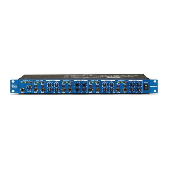
MAIN PHONES AUX IN MAIN INJECT The Samson S•phone headphone amplifier utilizes the latest technology in gain management design. Here are some of it’s features: • Four channel headphone mixer amplifier. • Three headphone outputs; two rear, plus one front panel output per channel. -
Page 6: Controls And Functions
Controls and Functions FRONT PANEL LAYOUT MASTER LEVEL dB CHANNEL LEVEL dB CHANNEL 1 CHANNEL LEVEL dB CHANNEL 2 -18 -12 CLIP -18 -12 CLIP -18 -12 CLIP -30 -24 MUTE / ON ST / 2CH MUTE / ON ST / 2CH MUTE / HEADPHONE VOLUME... - Page 7 Controls and Functions CHANNEL LEVEL dB CHANNEL 3 CHANNEL LEVEL dB CHANNEL 4 -18 -12 CLIP -18 -12 CLIP POWER MUTE / ON ST / 2CH MUTE / ON ST / 2CH VOLUME VOLUME MAIN PHONES AUX IN MAIN PHONES AUX IN MAIN 11 HEADPHONE OUTPUT - A front panel headphone...
-
Page 8: Operating The S•Phone
Operating the S•phone SETTING UP THE S•phone Setting up your S•phone Headphone Amplifier is a simple procedure, which takes only a few minutes. Remove all packing materials (save them in case of need for future service) and plug the provided AC power cord in the rear AC inlet, but don’t plug the power cable into a wall outlet just yet. -
Page 9: S•Phone Master Section
Operating the S•phone SETTING UP THE S•phone - Continued • Repeat the previous step for all Channels that have headphones connected, making sure to start the VOLUME knob completely counterclockwise and then slowly raising it until the desired level is achieved. If you have connected different models of headphones to the various Channel Headphone jacks, you may find that some require more gain than others to achieve the same volume. -
Page 10: S•Phone Channels
Operating the S•phone S • PHONE CHANNELS Headphone Output The S•phone’s Headphone Output jack accepts CHANNEL LEVEL dB CHANNEL 1 a standard 1/4” TRS connector for easy inter- -18 -12 CLIP -30 - face with most professional headphones. Once the MASTER VOLUME has been set, the chan- MUTE / ON ST / 2CH MUTE... -
Page 11: Stereo And Two Channel Modes
Operating the S•phone STEREO AND TWO-CHANNEL MODES Each of the S•phone’s four channels can be set to operate in two different modes: Stereo and 2 Channel. Stereo Mode Stereo mode is a normal operating mode where all mix inputs including MAIN, MASTER INJECT, as well as the Channel AUX input, maintain their stereo image throughout the signal path to each headphone output. -
Page 12: S•Phone Connections
S•phone Connections CUE MIX SET-UP FOR MULTITRACK VOCAL RECORDING SIGNAL FLOW SIGNAL FLOW SIGNAL FLOW SIGNAL FLOW SIGNAL FLOW SIGNAL FLOW SIGNAL FLOW SIGNAL FLOW VOCAL MIX FROM CONSOLE AUX 3 & 4 SIGNAL FLOW SIGNAL FLOW SIGNAL FLOW SIGNAL FLOW RHYTHM SECTION MIX FROM CONSOLE AUX 1 &... -
Page 13: Cue Mix Set-Up For Multitrack Rhythm Section Recording
S•phone Connections CUE MIX SET-UP FOR MULTITRACK RHYTHM SECTION RECORDING SIGNAL FLOW SIGNAL FLOW SIGNAL FLOW SIGNAL FLOW SIGNAL FLOW SIGNAL FLOW SIGNAL FLOW SIGNAL FLOW VOCAL MIX FROM CONSOLE AUX 3 & 4 SIGNAL FLOW SIGNAL FLOW SIGNAL FLOW SIGNAL FLOW RHYTHM SECTION MIX FROM CONSOLE AUX 1 &... -
Page 14: Linking Multiple S•Phones
S•phone Connections LINKING MULTIPLE S•phones Any number of S•phones’ can be linked together (daisy-chained), allowing you to monitor an input signal over more than twelve sets of headphones, or to give individual musicians more control over their own headphone mix. To do this, simply follow these basic steps: •... -
Page 15: Headphone Impedance And Sensitivity Ratings
(or lower sensitivity) headphones at the same channel Volume setting. Samson Technologies has no connection with any of these manufacturers, nor do we endorse any particular models for use with the S•phone. This is simply a reference listing for your convenience. For more information about any of these headphones, contact the manufacturer directly. -
Page 16: S•Phone Wiring Guide
S•phone Wiring Guide Unbalanced 1/4” Connector Signal Signal Tip (signal) Ground Ground Sleeve (ground) Balanced TRS 1/4” Connector Signal (ring) Tip (signal) Signal (tip) Ring (signal) Signal (tip) Ground Signal (ring) Ground Sleeve (ground) Sleeve (ground) Insert Cable 1/4” TRS connector to two 1/4” can be used to connect a stereo signal to the Channel AUX or Master Inject. -
Page 17: Specifications
Specifications Master Section (Rear Panel) Input 2 TRS Balanced 1/4" (Left-Right) or (Left mono) Impedance 15 k Ohms balanced Max. input level +26 dBu balanced CMRR: Min 40dB, >55 dB @ 1 kHz Master Section (Front Panel) Master Volume control 0 - 10 Master Level Meters 5 Segment LED (–30 to Clip) -
Page 18: Block Diagram
S•Phone Block Diagram LOGIC CONTROL LEFT / RIGHT BALANCE AUX / MAIN BLEND... - Page 19 Samson Technologies Corp. 575 Underhill Blvd. P.O. Box 9031 Syosset, NY 11791-9031 Phone: 1-800-3-SAMSON (1-800-372-6766) Fax: 516-364-3888 www.samsontech.com...
Need help?
Do you have a question about the S-phone and is the answer not in the manual?
Questions and answers