Table of Contents
Advertisement
Quick Links
Download this manual
See also:
Service Manual
INSTRUCTION MANUAL
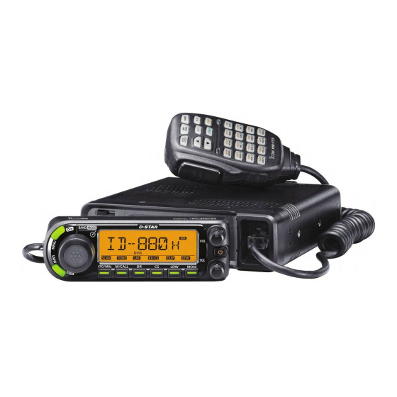
VHF/UHF DIGITAL TRANSCEIVER
ID-E880
This device complies with Part 15 of the FCC Rules. Operation is
subject to the following two conditions: (1) this device may not cause
harmful interference, and (2) this device must accept any interference
received, including interference that may cause undesired operation.
WARNING: MODIFICATION OF THIS DEVICE TO RECEIVE CEL-
LULAR RADIOTELEPHONE SERVICE SIGNALS IS PROHIBITED
UNDER FCC RULES AND FEDERAL LAW.
Advertisement
Table of Contents

Related Manuals for Icom ID-E880


Summary of Contents for Icom ID-E880
- Page 1 INSTRUCTION MANUAL VHF/UHF DIGITAL TRANSCEIVER ID-E880 This device complies with Part 15 of the FCC Rules. Operation is subject to the following two conditions: (1) this device may not cause harmful interference, and (2) this device must accept any interference received, including interference that may cause undesired operation.
-
Page 2: Foreword
We want to take a couple of mo- We want to take a couple of mo- simply ments of your time to thank you for making your ID-E880 your radio of choice, and hope you agree with Icom’s phi- Switchable VHF and UHF transceiver losophy of “technology first.”... -
Page 3: Precautions
NEVER operate or touch the transceiver with wet hands. This may Icom microphones only (supplied or optional). Other manufac- result in an electric shock or damage the transceiver. turers’ microphones have different pin assignments and may damage... -
Page 4: Supplied Accessories
Remote controller bracket ..........1 † Approx. Icom, Icom Inc. and the Icom logo are registered trademarks of Icom Incorporated (Japan) in the United States, the United King- dom, Germany, France, Spain, Russia and/or other countries. Microsoft, Windows and Windows Vista are registered trademarks of Microsoft Corporation in the United States and/or other coun- tries. -
Page 5: Table Of Contents
TABLE OF CONTENTS FOREWORD ····················································································· i Selecting output power ··························································18 EXPLICIT DEFINITIONS ··································································· i Operating mode selection ······················································18 FEATURES ························································································ i Squelch attenuator ·································································19 IMPORTANT ······················································································ i Monitor function ·····································································20 PRECAUTIONS ················································································ ii Audio mute function ·······························································20 SUPPLIED ACCESSORIES ···························································· iii One-touch PTT function·························································21 TABLE OF CONTENTS ······························································iv–vi 3 REPEATER OPERATION ···················································22–27... -
Page 6: Table Of Contents
TABLE OF CONTENTS Simplex operation in the VFO ················································56 8 SCAN OPERATION ························································100–110 Repeater operation in the VFO ··············································58 Scan types ···········································································100 Message operation ································································64 Full/band/programmed scan ···············································102 Automatic reply function ························································66 Scan edges programming ····················································103 EMR communication ······························································67 Memory scan ······································································105 Break-in communication ························································68 Memory bank scan ······························································106 Low-speed data communication ············································70... - Page 7 TABLE OF CONTENTS DTMF speed ········································································145 Clearing a DTMF memory ···················································145 12 TONE SQUELCH AND POCKET BEEP ························146–152 Tone/DTCS squelch (beep) operation ··································146 DTCS polarity setting ··························································149 Tone scan·············································································150 Digital squelch ·····································································151 13 OTHER FUNCTIONS ······················································153–161 Microphone keys ··································································153 All reset ················································································154 Partial reset··········································································154 Data cloning ·········································································155 Auto power OFF···································································157...
-
Page 8: Quick Reference Guide
QUICK REFERENCE GUIDE Installation D Installation methods D Precaution — magnets • Single body installation R CAUTION Magnets are used for the controller’s attachment to a metal Transceiver object. NEVER attach the controller on the main unit’s top cover, particularly around the internal speaker grill. It may cause the contents of the CPU and memory device to be deleted. - Page 9 QUICK REFERENCE GUIDE D Location Select a location which can support the weight of the trans- • Remote installation ceiver and does not interfere with driving. We recommend the locations shown in the diagram below. Controller NEVER place the transceiver or remote controller where normal operation of the vehicle may be hindered or where it could cause bodily injury.
-
Page 10: Microphone Connection
Adjust the angle for your suitable position. Spring washer Mounting bracket Flat washer Mounting nut 25° When using self-tapping screws IMPORTANT! Detailed installation notes for Icom mobile transceivers to be fitted into vehicles are available. Contact your Icom dealer or distributor. - Page 11 QUICK REFERENCE GUIDE D Controller’s attachment/detachment D Separation cable connection You can attach or detach the controller to/from the main unit Using the supplied separation cable the controller can (3.4 m), as below. be separated from the main unit, doubling as a remote con- troller.
- Page 12 QUICK REFERENCE GUIDE D Remote installation e Attach the supplied remote controller bracket as below. The supplied remote controller bracket is used for remote in- stallation. Remote controller • Attach the remote controller These screws bracket onto a flat surface are not supplied.
-
Page 13: Battery Connection
• CONNECTING TO A DC POWER SUPPLY Use a rubber grommet when passing the DC power cable through a metal plate to prevent a short circuit. • CONNECTING TO A DC POWER SOURCE ID-E880 Grommet to an DC power outlet ID-E880 supply 13.8 V... -
Page 14: Antenna Installation
QUICK REFERENCE GUIDE D Antenna installation • Antenna connector • Antenna location To obtain maximum performance from the transceiver, se- The antenna uses a PL-259 connector. lect a high-quality antenna and mount it in a good location. It • PL-259 CONNECTOR is not necessary to use radials on a magnetic mount (“mag q Slide the coupling ring 30 mm... -
Page 15: Your First Contact
2. Selecting the operating frequency band shack, you are probably anxious to get on the air. We would The ID-E880 can use the 2 m or 70 cm amateur bands. like to take you through a few basic operation steps to make your first time “On The Air”... - Page 16 QUICK REFERENCE GUIDE 3. Tune the frequency The tuning dial will allow you to dial in the frequency you want to use. Page 15 will instruct you on how to set the tuning speed. [DIAL] Rotate [DIAL] to tune the frequency. Using the HM-133 You can directly enter the frequency with the HM-133 keypad.
-
Page 17: Repeater Operation
QUICK REFERENCE GUIDE Repeater operation Using the HM-133 1. Setting duplex Plus or minus duplex selection and the repeater tone setting Push [BAND] then rotate [DIAL] to select the frequency can be done easily via the HM-133. band. Push [ 7(TONE)] for minus duplex;... -
Page 18: Programming Memory Channels
QUICK REFERENCE GUIDE Programming memory channels The ID-E880 has a total of 1052 memory channels Using the HM-133 (including q Push [MR/CALL] to select the memory mode. for storing often-used 25 pairs scan edges and 2 call channels) w Push [ operating frequency, repeater settings, etc. -
Page 19: Panel Description
PANEL DESCRIPTION Main unit r PACKET JACK [PACKET] (pgs. 157, 158) Connects a TNC , etc. for data (Terminal Node Controller) communications. The transceiver can support 1200/9600 bps packet communication (AFSK/GMSK) t EXTERNAL SPEAKER JACK [SP] Connects an 8 Ω speaker. •... -
Page 20: Front Panel
PANEL DESCRIPTION Front panel Function display (p. 4) BAND MODE VFO/MHz M/CALL MONI q MENU•LOCK KEY [MENU r BAND•MODE KEY [BAND•MODE] Push to enter the MENU screen indication ON or OFF. Push to enter band selection state. (p. 11) (p. 116) •... - Page 21 PANEL DESCRIPTION o OUTPUT POWER•DUPLEX KEY [LOW•DUP] During FM/FM-N mode operation, push and hold for 1 sec. to enter the tone function selection state. Each push changes the output power selection. (pgs. 23, 146) (p. 18) • Rotating [DIAL] selects the tone function. •...
-
Page 22: Function Display
PANEL DESCRIPTION Function display Function guide (p. 6) q TRANSMIT INDICATOR t OPERATING MODE INDICATOR (p. 18) Appears while transmitting. Shows the selected operating mode. (p. 17) w CALL SIGN TYPE INDICATORS • FM, FMN (FM narrow), AM, NAM (AM narrow) and DV (Digital voice) are available. - Page 23 PANEL DESCRIPTION i MEMORY CHANNEL NUMBER INDICATORS !5 TONE INDICATOR Shows the selected memory channel number. • During FM/FM-N mode operation: (pgs. 12, 88) Shows the selected bank initial. “T” appears while the repeater tone is in use. (p. 93) (p.
-
Page 24: Function Guide Indicator
PANEL DESCRIPTION q CLEAR KEY [CLR](DR) D Function guide indicator During programming state for call signs, repeater list, The function guides give you easy menu access to a variety memory name, etc., push to erase the selected charac- of functions. Two function guides are available. ter. -
Page 25: Microphone
PANEL DESCRIPTION Microphone (HM-133) e UP/DOWN KEYS [Y]/[Z] Push either key to change operating frequency, memory channel, set mode setting, etc. (pgs. 12, 14, 88, 117) Push and hold either key for 1 sec. to start scanning. (p. 107) r ACTIVITY INDICATOR Mic element Lights red while any key, except [FUNC] and [DTMF-S], is pushed, or while transmitting. -
Page 26: Microphone Keypad
PANEL DESCRIPTION Microphone keypad FUNCTION SECONDARY FUNCTION ( +key) OTHER FUNCTIONS Switches between opening and closing the In the VFO mode, selects the operating After pushing squelch. bands. (p. 20) (p. 11) Transmits the appropriate In the memory mode enters bank selection DTMF code. - Page 27 PANEL DESCRIPTION FUNCTION SECONDARY FUNCTION ( +key) OTHER FUNCTIONS Cancels frequency entry. Stores the set frequency, etc., into the (p. 15) After pushing Cancels the scan or priority watch. selected memory channel when pushed Transmits the appropriate and held. (pgs. 107, 114) (p.
-
Page 28: Optional Microphone
PANEL DESCRIPTION Optional Microphone (HM-154) q PTT SWITCH Push and hold to transmit; release to receive. w UP/DOWN KEYS [UP]/[DN] Push either key to change operating frequency, memory channel, set mode setting, etc. (pgs. 12, 14, 88, 117) Push and hold either key for 1 sec. to start scanning. (p. -
Page 29: Basic Operation
D Operating frequency band selection x Push [Y]/[Z] to select the desired frequency band. The ID-E880 has 2 m and 70 cm bands for transmission and c Push [ A(MW)] to exit the state, and return reception. In addition, extra frequency bands 127, 220, 350, to the frequency indication. -
Page 30: Vfo Mode
BASIC OPERATION D VFO mode D Memory mode VFO mode is used to set the desired frequency. Memory mode is used for operation on the memory channels which store programmed frequencies. Push [VFO/MHz] to select the VFO mode. q Push [M/CALL] to select the memory mode. •... -
Page 31: Call Channels
BASIC OPERATION D Call channels D DR (D-STAR Repeater) mode Call channels are used for quick recall of most-often used DR (D-STAR Repeater) mode is used for D-STAR repeater frequencies. operation. In this mode, you can select the pre-programmed repeaters and UR call sign easily. q Push [M/CALL] several times to select call channels. -
Page 32: Using The Tuning Dial
BASIC OPERATION Using the tuning dial Using the [Y]/[Z] keys Push [Y] or [Z] to select the desired frequency. q Rotate [DIAL] to set the frequency. • Pushing and holding [Y]/[Z] for 1 sec. activates a • If the VFO mode is not selected, push [VFO/MHz] to select the scan. -
Page 33: Using The Keypad
BASIC OPERATION Using the keypad Tuning step selection The frequency can be set directly via numeral keys on the Tuning steps are the minimum frequency change increments microphone. when you rotate [DIAL] or push [Y]/[Z] on the microphone. Independent tuning steps for each frequency band can be z Push [VFO/LOCK] to select the VFO mode, if set for your convenience. -
Page 34: Lock Functions
BASIC OPERATION Lock functions D Microphone keypad lock To prevent accidental frequency changes and unnecessary function access, use the lock function. The transceiver has 2 This function locks the microphone keypad. different lock functions. Push [FUNC] then [ SQL Z D(16KEY-L)] to turn D Frequency lock 16KEY-L... -
Page 35: Receiving
Appears when receiving a signal. IMPORTANT! (for 50 W transmission): CONVENIENT! The ID-E880 is equipped with protection circuits to protect The audio and squelch level can also be adjusted with SQL / the power amplifier circuit from high temperature. When... -
Page 36: Selecting Output Power
BASIC OPERATION Selecting output power Operating mode selection The transceiver has 3 output power levels to suit your operat- Operating modes are determined by the modulation of the ing requirements. Low output powers during short-distance radio signals. The transceiver has total 5 operating modes communications may reduce the possibility of interference to . -
Page 37: Squelch Attenuator
BASIC OPERATION Squelch attenuator D Squelch attenuator setting The transceiver has an RF attenuator related to the squelch q Enter “AT-ATT” in FUNC set mode (SET). level setting. Approx. 10 dB attenuation is obtained at maxi- mum setting. MENU FUNC AT-ATT (p. -
Page 38: Monitor Function
BASIC OPERATION Monitor function Audio mute function This function is used to listen to weak signals without disturb- This function temporarily mutes the audio without disturbing ing the squelch setting. the volume setting. (microphone only) Push [FUNC] then [ D(MUTE)] to mute SQL Y MUTE audio signals. -
Page 39: One-Touch Ptt Function
BASIC OPERATION One-touch PTT function The PTT switch can be operated as a one-touch PTT switch (each push toggles between transmit/receive). Using this function you can transmit without pushing and holding the PTT switch. To prevent accidental, continuous transmissions with this function, the transceiver has a time-out timer. -
Page 40: Repeater Operation
REPEATER OPERATION General • Repeater operation flow chart Repeaters allow you to extend the operational range of your radio because a repeater has much higher output power than Step 1: the typical transceiver. Set the desired band to operate the repeater. Usually, a repeater has independent frequencies for receive and transmit. -
Page 41: Accessing A Repeater
REPEATER OPERATION Accessing a repeater y Push and hold [PTT] to transmit. q Set the receive frequency (repeater output frequency). • The displayed frequency automatically changes to the transmit (pgs. 14, 15) w Push and hold [DUP](LOW) for 1 sec. to enter the duplex frequency (repeater input frequency). - Page 42 REPEATER OPERATION Accessing repeater (continued) z Set the receive frequency m Push [ (repeater output fre- 9(TSQL)] to return to simplex opera- SIMP DUP– SIMP quency). (pgs. 14, 15) tion. x Push [ – 7(TONE)] to select minus duplex; • “DUP+” or “DUP–” indicator disappears. push [ + 8(TSQLS)] to select plus du- DUP+...
-
Page 43: Subaudible Tones (Encoder Function)
REPEATER OPERATION Subaudible tones (Encoder function) z Set mode/channel for which you wish to set the D Subaudible tones q Select mode/channel for which you wish to set the subau- subaudible tones, such as the VFO mode or a memory/call channel. (Subaudible tone is avail- dible tones, such as the VFO mode or a memory/call chan- able in FM/FM-N only.) nel. -
Page 44: Dtmf Tones
REPEATER OPERATION D DTMF tones D 1750 Hz tone Push [DTMF-S], then push the keys of the de- The microphone has 1750 Hz tone capability, used for ring DTMF-S sired DTMF digits. tone when calling, etc. • The function indicator lights green. z Push [FUNC]. -
Page 45: Frequency Offset
REPEATER OPERATION Frequency offset z Push [BAND] to select the desired band. When communicating through a repeater, the transmit fre- • Enter the desired frequency via the keypad if neces- quency is shifted from the receive frequency by an amount sary. -
Page 46: Dv Mode Programming
Internet Internet network network About time-out timer function 10 GHz The ID-E880 has a time-out timer function for digital re- Repeater D Repeater C peater operation. The timer limits a continuous transmis- 430 MHz 430 MHz sion to approx. 10 min. Warning beeps will sound approx. - Page 47 DV MODE PROGRAMMING D System description Area 1 Area 2 Area 3 (Gateway) Area 4 Repeater 1 Repeater 2 Repeater 3 Repeater 4 Zone A Internet Internet Network Network Area 8 Area 5 Area 6 (Gateway) Area 7 Repeater 5 Repeater 6 Repeater 7 Repeater 8...
-
Page 48: Call Sign Programming
DV MODE PROGRAMMING Call sign programming e Push [ ](LOW) to enter call sign programming mode. Four types of current call sign memory are available; “MY” (my call sign=your own call sign) “UR” (your call sign=other sta- • The 1st digit blinks. tion call sign) “RPT1”... - Page 49 DV MODE PROGRAMMING u Repeat step r (at previous page) to program the desired 4 character note. i Push [ ](MONI) to store the programmed call sign with note and return to call sign screen. o Push [MENU ] to return to frequency indication.
-
Page 50: Station Call Sign Programming
For your information e Push [ ](LOW) to enter call sign programming mode. The ID-E880 has a call sign edit record function. • The 1st digit blinks. When editing a call sign stored in a call sign memory (or reg- ular memory/call channel), the default setting is to store the edited call sign into a blank channel automatically. -
Page 51: Current Repeater Call Sign Programming
DV MODE PROGRAMMING D Current repeater call sign programming “RPT1” or “RPT2” can store current call sign only, and re- peater call signs must be stored in the repeater list (p. 34). q Enter “RPT1” or “RPT2” in call sign screen. MENU CALL-S RPT1 or RPT2... -
Page 52: Repeater List
NOTE: Repeater lists can be erased by static electricity, elec- tric transients, etc. In addition, they can be erased by mal- The ID-E880 can store up to 300 repeater call signs. The re- function and during repairs. Therefore, we recommend that... -
Page 53: Repeater List Programming
DV MODE PROGRAMMING Repeater list programming D New repeater list programming Repeater call sign programming (CALL S) t Push [ ](MONI) to enter the repeater call sign program- q Enter “ADD-L” in RPT-L menu. ming state. See p. 39 for repeater call sign programming MENU RPT-L ADD-L... - Page 54 Repeater group programming (GROUP) i Push [ ](MONI) to enter the gateway repeater call sign The ID-E880 has a total of 10 groups (0–9). You can assign programming state. See p. 40 for gateway repeater call and organize up to 300 repeater lists in the 10 groups. Group sign programming details.
- Page 55 DV MODE PROGRAMMING Access repeater setting (R1 USE) Frequency programming (FREQ) The programmed repeater lists are assigned to use or not This content appears when R1 USE is selected YES. to use the access repeater (RPT1) in the DR mode. To use !9 Push [ ](MONI) to enter the frequency programming for RPT1, repeater frequency, duplex direction and frequency state.
- Page 56 DV MODE PROGRAMMING Duplex direction setting (DUP) @9 Rotate [DIAL] to select the frequency offset. This content appears when R1 USE is selected YES. • The selected number blinks. @4 Push [ ](MONI) to enter the duplex direction setting • Push [ ](LOW) to move the cursor right; push [ ](CS) to move state.
- Page 57 DV MODE PROGRAMMING Repeater name programming (R-NAME) Repeater call sign programming (CALL S) q Push [ ](MONI) to enter the repeater name programming q Push [ ](MONI) to enter the repeater call sign program- state. ming state. • Repeater name programming screen is displayed. •...
-
Page 58: Changing A Repeater List
DV MODE PROGRAMMING ■ Changing a repeater list ® Gateway repeater call sign programming (GW CAL) q Push [ ](MONI) to enter the gateway repeater call sign programming. This function re-programs a repeater list’s contents. This is useful when already-programmed contents are mistaken or •... -
Page 59: Clearing A Repeater List
DV MODE PROGRAMMING Clearing a repeater list e Rotate [DIAL] to select the desired repeater list to be Contents of programmed list can be cleared (erased). changed. r Push [ ](MONI) to enter the list. q Enter “EDIT-L” in RPT-L menu. MENU RPT-L EDIT-L... -
Page 60: Dv Mode Operation
Digital mode operation Quick entry Push [CS] to enter the current call sign mode. See next The ID-E880 can be operated in digital voice mode and low- page for details. speed data operation for both transmit and receive. It can also be connected to a GPS receiver •... -
Page 61: Receiving A D-Star Repeater
Receiving a D-STAR repeater D Confirming current call sign When the ID-E880 receives a signal from a D-STAR repeater, q Push [CS] to enter the current call sign mode. it receives four call signs: caller’s call sign, called call sign, repeater call sign 1 (the repeater that caller accessed), and •... -
Page 62: Received Call Sign
DV MODE OPERATION Received call sign Call record channel When a call is received in the DV mode, the calling station and the repeater call signs being used can be stored into the received call record. The stored call signs are viewable in the following manner. - Page 63 DV MODE OPERATION D One-touch reply using the call record The stored call signs in the call record can be used to call the Important! other station. Setting call signs with the “One-touch reply using the call record” operation as at left are for temporary operation q After receiving a call, push and hold [RX CS](CS) for only.
-
Page 64: Copying The Call Sign
DV MODE OPERATION Copying the call sign D Copying the call sign memory contents NOTE: Make sure that the “EDIT R (EDIT RECORD)” item in DV This function is convenient when modifying a part of the cur- set mode is set to “AUTO” or “SEL” in advance. rent call sign. -
Page 65: D Copying The Call Record Contents Into Call Sign Memory
DV MODE OPERATION D Copying the call record contents into call sign memory t Rotate [DIAL] to select the desired call sign to be copied This is a way to copy the call record contents (“CALLER,” into call sign memory “RXRPT1”... -
Page 66: Dr (D-Star Repeater) Mode Operation
DV MODE OPERATION DR (D-STAR Repeater) mode operation D Access repeater scan DR (D-STAR Repeater) mode is used for D-STAR repeater operation. In this mode, you can select the pre-programmed q Push [DR] to select the DR mode. repeaters and UR call sign by using [DIAL]. •... - Page 67 DV MODE OPERATION • Skip setting Unwanted access repeater can be skipped for rapid selection or scan. q Enter “EDIT-L” in RPT-L menu. MENU RPT-L EDIT-L (Push [MENU ]), (rotate [DIAL], then push [ ](MONI).) • Programmed repeater name appears. w Rotate [DIAL] to select the desired access repeater to be skipped.
-
Page 68: Calling Cq
DV MODE OPERATION Calling CQ e Rotate [DIAL] to select the access repeater. STEP 1 (RPT1 selection) q Push [DR] to enter the DR mode. • Only repeaters that have access repeater settings programmed are selectable. Appears • Group indicator appears momentarily when rotating [DIAL]. •... - Page 69 DV MODE OPERATION D Calling CQ in the same area (Area CQ) • Calling CQ in another zone (Different zone CQ) Zone Zone A Area Gateway Area My call sign Repeater q Repeater q NARA43 (JP3YHL) NARA43 JA3YUA MY call sign (JP3YHL) JA3YUA Repeater e...
-
Page 70: Calling A Specific Station
DV MODE OPERATION Calling a specific station e Rotate [DIAL] to select the access repeater. STEP 1 (RPT1 selection) q Push [DR] to enter DR mode. • Only repeaters that have access repeater settings programmed are selectable. Appears • Group indicator appears momentarily when rotating [DIAL]. •... - Page 71 DV MODE OPERATION D Calling a specific station in the same area D Calling a specific station in the same zone (Area call) (Zone call) Zone Zone Area Area Repeater q NARA43 (JP3YHL) MY call sign Station call sign Repeater q NARA43 MY call sign Station call sign JA3YUA...
- Page 72 DV MODE OPERATION D Calling a specific station in another zone (Different zone call) Continued instructions from step t on page 52. STEP 3 (RPT2 selection) Zone A y Push and hold [UR](DR) for 1 sec. to enter the linked re- peater (RPT2) selection.
- Page 73 DV MODE OPERATION D Confirming the setting D One-touch reply using the call record in the q Push [CS] to enter the setting confirmation screen. DR mode • Either “UR,” “R1” or “R2” call sign is displayed. The stored call signs in the call record can be used to the call. See p.
-
Page 74: Simplex Operation In The Vfo
DV MODE OPERATION Simplex operation in the VFO D Sending CQ t Release [PTT] to return to receive. q Set the desired frequency. (pgs. 14, 15) • The other station’s call sign will be received. • Select output power, if desired. (p. 18) w Set the current MY call sign to your own call sign. - Page 75 DV MODE OPERATION t Release [PTT] to return to receive. D Calling a specific station • The other station’s call sign will be received. q Set the desired frequency. (pgs. 14, 15) • Received call signs can be stored into the received call record •...
-
Page 76: Repeater Operation In The Vfo
DV MODE OPERATION Repeater operation in the VFO v Rotate [DIAL] to select “R2,” linked repeater’s call sign, then D Calling CQ in the same area (Area CQ) push [ ](MONI) to set the current call sign selection mode. q Set the desired repeater’s frequency, offset and shift direc- •... - Page 77 DV MODE OPERATION D Calling specific station in the same area (Area call) q Set the desired repeater’s frequency, offset and shift direc- v Rotate [DIAL] select “R2,” linked repeater’s call sign, then push tion (pgs. 14, 15, 23, 27), then select the DV mode (p. 18). [ ](MONI) to set the current call sign selection mode.
- Page 78 DV MODE OPERATION D Calling CQ in the same zone (Zone CQ) q Set the desired repeater’s frequency, offset and shift direc- v Rotate [DIAL] to select “R2,” linked repeater’s call sign, then push [ ](MONI) to set the current call sign selection mode. tion (pgs.
- Page 79 DV MODE OPERATION D Calling a specific station in the same zone (Zone call) q Set the desired repeater’s frequency, offset and shift direc- v Rotate [DIAL] to select “R2,” linked repeater’s call sign, then tion (pgs. 14, 15, 23, 27), then select the DV mode (p. 18). push [ ](MONI) to set the current call sign selection mode.
- Page 80 DV MODE OPERATION D Calling CQ in another zone (Different zone CQ) q Set the desired repeater’s frequency, offset and shift direc- m Rotate [DIAL] to select the specified gateway repeater tion (pgs. 14, 15, 23, 27), then select the DV mode (p. 18). call sign in the same zone, then push [ ](MONI).
- Page 81 DV MODE OPERATION D Calling a specific station in another zone (Different zone call) q Set the desired repeater’s frequency, offset and shift direc- m Rotate [DIAL] to select the specified gateway repeater tion (pgs. 14, 15, 23, 27), then select the DV mode (p. 18). call sign in the same zone, then push [ ](MONI).
-
Page 82: Message Operation
DV MODE OPERATION Message operation D TX message programming t Repeat the step r to enter the desired message. TX messages are available for up to 5 channels and each • Up to 20 character messages can be set. channel can be programmed with a message of up to 20 characters. -
Page 83: Message Transmission
• TM1 to TM5 are available. r Push [ ](MONI) to set the message for transmission. NOTE: Only one message can be stored in the ID-E880. The received message is cleared by turning power OFF, t Push [PTT] to transmit. -
Page 84: Automatic Reply Function
DV MODE OPERATION Automatic reply function D RX message indication The automatic reply function replies to calls by a station that specified your call sign. The received message can also be checked in MESSAG (message) screen. D Automatic reply function setting q Select “RX MSG”... -
Page 85: Emr Communication
DV MODE OPERATION EMR communication r Push [MENU The EMR (Enhanced Monitor Receive) communication ] to return to frequency indication. mode is available for digital mode operation. In the EMR communication mode, no call sign setting is necessary. “EMR” appears When an EMR communication mode signal is received, the audio (voice) will be heard at the specified level even if the t Push [PTT] to transmit. -
Page 86: Break-In Communication
DV MODE OPERATION Break-in communication t Push [MENU ] to return to frequency indication. The break-in function allows you to break into a conversa- tion, where the two original stations are communicating with call sign squelch enabled. “BK” appears q While receiving an another station’s communication, push y When both stations are in standby, push [PTT] to transmit and hold [RX CS](CS) for 1 sec. - Page 87 DV MODE OPERATION • How to use break-in? While operating with the digital call sign squelch (p. 151) the squelch never opens even if a call is (no audio sounds) received, unless your own call sign is specified. (“MY”) However, when the call including the “BK ON” signal is received, the squelch will open and audio (break-in call) sounds even if the call is specified for another station.
-
Page 88: Low-Speed Data Communication
DV MODE OPERATION Low-speed data communication D Low-speed data communication application In addition to the digital voice communication, low-speed data communication is available. setting Use the optional OPC-1529R with DATA COMMUNICATION CABLE Configure the serial data communication software as follows. third-party serial data communication software. -
Page 89: Transmission Condition Setting
DV MODE OPERATION D Transmission condition setting q Enter “DATATX” in DV SET mode. MENU DV SET DATATX (Push [MENU ]), (rotate [DIAL], then push [ ](MONI).) w Rotate [DIAL] to select “PTT” or “AUTO.” : The input data from [DATA] are transmitted when pushing [PTT]. -
Page 90: Other Function In The Dv Mode
(poor E880 DV automatic detection switches to monitor in the FM data throughput performance). In such a case, the ID-E880 mode. displays “P-LOSS” instead of frequency indication on the dis- play to indicate Packet Loss has occurred. -
Page 91: Gps/Gps-A Operation
DV* modes. You can also transmit GPS data when in DV mode. To receive GPS data, connect a third-party GPS re- ceiver that has an RS-232C output and NMEA data format. Third-party GPS receivers connect to the ID-E880 [DATA] jack. In addition, the GPS message transmission is also available... -
Page 92: D Sentence Formatter Setting
The GSV sentence is incompatible with them. Those trans- ceivers will not display GPS messages properly if sent as a GSV sentence from the ID-E880. w Rotate [DIAL] to select “DVG.” e Push [ ](MONI) to select GPS sentence screen. -
Page 93: D Gps Message Programming
GPS/GPS-A OPERATION D GPS message programming D GPS message automatic transmission q Enter “TX GPS” in MESSAG screen. q Enter “GPS.ATX” in GPS mode. MENU MESSAG TX GPS MENU GPS.ATX (p. 141) (Push [MENU ]), (rotate [DIAL], then push [ ](MONI).) (Push [MENU ]), (rotate [DIAL], then push [ ](MONI).) •... -
Page 94: Position Indication
GPS/GPS-A OPERATION D Received GPS message indication D Position indication q Enter “RX GPS” in MESSAG screen. q Enter “GPS.POS” in GPS mode. MENU MESSAG RX GPS MENU GPS.POS (Push [MENU ]), (rotate [DIAL], then push [ ](MONI).) (Push [MENU ]), (rotate [DIAL], then push [ ](MONI).) •... - Page 95 GPS/GPS-A OPERATION • Selectable items • Position indication My position My position Received position North or South My position 35°45.00’N 135°35.00’E Elevation S/RF meter indicates the selection Time East or West Distance MONI Push Push Push Depending on the connected GPS receiver, “TIME” indica- Caller tion is not available.
-
Page 96: Displaying Direction And Forward
GPS/GPS-A OPERATION D Saving own/received position data D Displaying direction and forward q Enter “GPS.POS” in GPS mode. Displaying own direction, received station’s direction and set position and direction in the GPS memory. MENU GPS.POS (Push [MENU ]), (rotate [DIAL], then push [ ](MONI).) q Enter “D/F”... - Page 97 GPS/GPS-A OPERATION • Direction indication example (N -- --) (NW --) (NE --) (W -- --) (E -- --) GPS.M (SW --) (SE --) (S -- --)
-
Page 98: Gps Data Addition
GPS/GPS-A OPERATION D GPS data addition q Enter “GPS.MEM” (GPS memory) in GPS mode. r Rotate [DIAL] to select the desired character or number. MENU GPS.MEM (Push [MENU ]), (rotate [DIAL], then push [ ](MONI).) • GPS memory selection screen is displayed. •... -
Page 99: Gps Alarm Setting
GPS/GPS-A OPERATION D GPS alarm setting e Push [ ](MONI), then rotate [DIAL] to select the desired GPS alarm sounds when your own position is close the spec- ified position. This function can be set to use information from memory channel. •... -
Page 100: Gps Alarm Setting In Gps Memory Channel
GPS/GPS-A OPERATION D GPS alarm setting in GPS memory channel r Push [ ](CS) to return to GPS.MEM (GPS memory) GPS alarm setting for a specified GPS memory channel is screen. available on GPS memory channel indication. t Push [MENU ] to return to frequency indication. -
Page 101: Gps Memory Clearing
GPS/GPS-A OPERATION D GPS memory clearing • Clear desired memory channel to be cleared • Clear all memory channels q Enter “GPS.MEM” in GPS set mode as described at left. q Enter “GPS.MEM” in GPS set mode. w Rotate [DIAL] to select the desired GPS memory channel MENU GPS.MEM to be cleared. -
Page 102: Alarm Area
GPS/GPS-A OPERATION D Alarm area 1 Sets GPS alarm active range from 00.08′ to 59.99′ in 00.01′ • Example: Your position : 35°N/135°E steps. (default: 00.25′) ALM AREA1 setting : 00.25’ (default) q Enter “ALM1” in GPS set mode. 00.25’ 00.25’ Point B Point A MENU... - Page 103 GPS/GPS-A OPERATION D Alarm area 2 Selects GPS alarm active range from “BOTH,” “EXTEND” and • Example: “LIMIT” when “CH” or “RX” is selected at GPS alarm setting. q Enter “ALM2” in GPS mode. Extended range (approx. 1 km; 1094 Y) MENU ALM2 (Push [MENU...
-
Page 104: Gps-A Operation
Set the following to activate the GPS-A function. In GPS-A operation, the following codes are transmitted to q Select the DV mode operation (p. 18) the PC connected to the ID-E880. GPS-A code is based on w Select “GPS-TX” (GPS transmission mode) to DVA. ®... -
Page 105: Memory/Call Channels
MEMORY/CALL CHANNELS General description The transceiver has 1050 memory channels, and 2 call chan- NOTE: nels. Memory channels include 50 scan edge memory chan- Memory data can be erased by static electricity, electric nels (25 pairs) for storage of often-used frequencies. transients, etc. -
Page 106: Selecting A Memory Channel
MEMORY/CALL CHANNELS Selecting a memory channel D Using the tuning dial D Using the keypad q Push [M/CALL] several times to select the memory z Push [MR/CALL] to select the memory mode. MR/CALL mode. • “X” indicator appears. x Push [ C(T-OFF)] to activate the keypad w Rotate [DIAL] to select the desired memory channel. -
Page 107: Selecting A Call Channel
MEMORY/CALL CHANNELS Selecting a call channel Call channel is a pre-programmed memory channel that can be accessed by simply pushing call channel button. Push [M/CALL] several times to select the call channel mode, then rotate [DIAL] to select the desired call channel. •... -
Page 108: Memory Channel Programming
MEMORY/CALL CHANNELS Memory channel programming q Push [VFO/MHz] to select the VFO mode. t Push and hold [MW](S.MW) for 1 sec. to program. w Set the desired frequency: • 3 beeps sound. • Memory channel number automatically increases when continu- Select the desired band with [BAND]. - Page 109 MEMORY/CALL CHANNELS D Programming a memory channel via the microphone The microphone can also be used to program mem- ory channels. v Push [VFO/LOCK] to select the VFO mode. z Set the desired frequency in the VFO mode. b Push [FUNC] then push and hold [ A(MW)] for 1 sec.
-
Page 110: Memory Bank Setting
MEMORY/CALL CHANNELS Memory bank setting t Rotate [DIAL] to select the desired bank group from “A” to The ID-E880 has a total of 26 banks . Regular memory (A to Z) channels, 0 to 999, are assigned to any desired bank for easy “Z”. -
Page 111: Memory Bank Selection
MEMORY/CALL CHANNELS Memory bank selection r Rotate [DIAL] to select the bank channel. q Push [M/CALL] several times to select the memory mode. w Push [BAND] to enter the bank selection state. • Only programmed banks are displayed. e Rotate [DIAL] to select the desired memory bank group, then push [BAND] again. -
Page 112: Programming Memory/Bank/Scan Name
MEMORY/CALL CHANNELS Programming memory/bank/scan name i Repeat step u until the desired channel name is pro- Each memory channel can be programmed with an alpha- numeric channel name for easy recognition and can be in- grammed. o Push [ dicated independently by channel. Memory and scan names ](MONI). -
Page 113: Selecting Memory/Bank Name Indication
MEMORY/CALL CHANNELS [EXAMPLE]: Selecting memory/bank Programming the memory name name indication “AIR” into the scan edge channel 3A. [S.MW [DIAL] During memory mode operation, either the programmed memory name or bank name can be displayed. During memory mode, rotate Rotate [DIAL] to enter “A,” [DIAL] to select 3A. -
Page 114: Copying Memory/Call Contents
MEMORY/CALL CHANNELS Copying memory/call contents This function copies a memory channel’s contents to the VFO . This is useful when searching (or another memory/call channel) for signals around a memory channel frequency and for re- calling the frequency offset, subaudible tone frequency etc. D Memory/call VFO z Select the memory/call channel to be copied. - Page 115 MEMORY/CALL CHANNELS D Memory/call call/memory q Select the memory (call) channel to be copied. Push [M/CALL] several times to select the memory mode or call channel mode, then rotate [DIAL] to select the desired channel. w Push [S.MW] to enter the select memory write mode. •...
-
Page 116: Memory Clearing
MEMORY/CALL CHANNELS Memory clearing Contents of programmed memories can be cleared (erased), r Push [MENU ] to the previous indication before enter- if desired. ing the select memory write mode. q Push [S.MW] to enter the select memory write mode. NOTE: Be careful!—... -
Page 117: Erasing/Transferring Bank Contents
MEMORY CHANNEL OPERATION Erasing/transferring bank contents e Push [ The bank contents of programmed memory channels can be ](MONI) to select “BANK” setting, then push [ cleared or reassigned to another memory bank. (MONI) again. INFORMATION: Even if the memory bank contents are cleared, the memory channel contents still remain programmed. -
Page 118: Scan Operation
SCAN OPERATION Scan types Scanning searches for signals automatically and makes it easier to locate new stations for contact or listening pur- poses. FULL SCAN Repeatedly scans all frequen- SELECTED BAND SCAN Repeatedly scans all frequen- (p. 102) cies over the entire band. cies over the entire selected (p. - Page 119 SCAN OPERATION MEMORY (SKIP) SCAN Repeatedly scans memory BAND MEMORY (SKIP) SCAN (p. 105) channels except those set as Repeatedly scans memory channels in the same band as dis- (pgs. 105, 108) skip channel. played band. SKIP This setting can be turned ON or OFF for each memory SKIP channel.
-
Page 120: Full/Band/Programmed Scan
SCAN OPERATION Full/band/programmed scan t Push [SCAN](VFO/MHz) to start the scan. q Push [VFO/MHz] to select the VFO mode • Scan pauses when a signal is received. • Select the desired frequency band with [BAND] and [DIAL], if • Rotate [DIAL] to change the scanning direction. This also desired. -
Page 121: Scan Edges Programming
SCAN OPERATION Scan edges programming r Rotate [DIAL] to select the desired programmed scan Scan edges can be programmed in the same manner as edge channel from 0A to 24A. memory channels. Scan edges are programmed into scan t Push and hold [MW](S.MW) for 1 sec. edges, 0A/0B to 24A/24B, in memory channels. - Page 122 SCAN OPERATION D Programming scan edges via the microphone z Push [MR/CALL] to select the memory mode. v Push [FUNC], then push and hold [ A(MW)] for 1 sec. x Select scan edge channel, 0A to 24A using to program. •...
-
Page 123: Memory Scan
SCAN OPERATION Memory scan t Push [SCAN](VFO/MHz) to start the scan. IMPORTANT: To perform memory scan, 2 or more mem- • Scan pauses when a signal is received. ory channels MUST be programmed, otherwise the scan • Rotate [DIAL] to change the scanning direction. This also will not start. -
Page 124: Memory Bank Scan
SCAN OPERATION Memory bank scan r Rotate [DIAL] to select the desired scanning type. IMPORTANT: To perform memory bank scan, 2 or more • “ALL” for all bank scan; “B-LINK” for bank link scan or “BANK- ” bank channels MUST be programmed, otherwise the scan for bank scan ( = A to Z;... - Page 125 SCAN OPERATION D Scan start/stop via the microphone z Push [VFO/LOCK] to select the VFO mode for • For memory bank scan SCAN full/band/programmed scan; push [MR/CALL] to SCAN “ALL” for all bank scan; “B-LINK” for bank link scan select the memory mode for memory scan. or “BANK- ”...
-
Page 126: Skip Channel/Frequency Setting
SCAN OPERATION Skip channel/frequency setting r Rotate [DIAL] to select “SKIP,” then push [ ](MONI). Memory channels can be set to be skipped during memory skip scan. In addition, memory channels can be set to be skipped during both memory skip scan and frequency skip scan. -
Page 127: Scan Resume Condition
SCAN OPERATION Scan resume condition D Scan resume timer D Scan pause timer The scan restarts after the signal disappears according to the The scan pauses when receiving signals according to the resume time. It can be set from 0–5 sec. or unlimited. scan pause time. - Page 128 SCAN OPERATION Skip channel/frequency setting (continued) Setting Pause timer via the microphone z Push [BAND] to select the desired band. x Enter “PAUSE” in SCAN menu. MENU SCAN PAUSE (p. 123) (Push [ B(D-OFF)] to enter MENU screen), (Push [Y] or [Z], then push [ B(D-OFF)].) c Push [Y]/[Z] to select the scan resume condi- tion, then push [...
-
Page 129: Priority Watch
PRIORITY WATCH Priority watch types MEMORY SCAN WATCH While operating on a VFO fre- 5 sec. Mch 0 Priority watch checks for signals on the frequency every quency, priority watch checks Mch 1 SKIP 5 sec. while operating on a VFO frequency or scanning (ex- for signals on each memory Mch 2 frequency... -
Page 130: Priority Watch Operation
PRIORITY WATCH Priority watch operation D Memory/call channel and memory scan watch y Push [MENU ] to cancel the watch. q Select the VFO mode; then, set an operating frequency. w Select the channel(s) to be watched. • During priority watch For memory channel watch: Select the desired memory channel. - Page 131 PRIORITY WATCH D VFO scan watch q Select the channel(s) to be watched. u Push [SCAN](VFO/MHz) to start the VFO scan watch. For memory channel watch: • The transceiver checks the memory/bank channel(s) or call Select the desired memory channel. channel every 5 sec.
- Page 132 PRIORITY WATCH D Memory/call channel and memory scan watch D VFO scan watch via the microphone via the microphone z Select the VFO mode; then, set the desired fre- PRIO z Select the VFO mode; then, set the desired fre- quency.
- Page 133 PRIORITY WATCH D VFO scan watch via the microphone (Continued) n Push [ 2(T-SCAN)] to start the VFO scan SCAN PRIO watch. • The transceiver checks the memory/bank channel(s) or call channel every 5 sec. • The watch resumes according to the selected scan resume condition.
-
Page 134: Menu Screen Operation
MENU SCREEN OPERATION General e Rotate [DIAL] to select “SOUNDS,” then push [ MENU screen is used for programming infrequently changed values or conditions of functions. (MONI).* • Push [Ω](CS) to select the previous indication. r Rotate [DIAL] to select “KEY B,” then push [ ](MONI).* D Entering MENU screen and operation •... - Page 135 MENU SCREEN OPERATION D Entering MENU screen via the microphone c Push [Y] or [Z] to select “SOUNDS,” then push [ The microphone can also be used to set the MENU B(D- screen settings. OFF)]. • Push [ C(T-OFF)] to select the previous indication. z Push [ v Push [Y] or [Z] to select “KEY B,”...
-
Page 136: Menu Screen Indication And Arrangement
MENU SCREEN OPERATION MENU screen indication and arrangement MENU screen shows one of the following indication. • TS mode • DV SET mode Independent items Setting (see p. 15) (see p. 134) • DUP.T mode • CALL-S mode Independent items Independent items (see p. -
Page 137: Items List
MENU SCREEN OPERATION Items list Items list D SET mode D TS mode See page 15 for details. - FUNC mode - SOUNDS mode Item Item Item Item Ref. Ref. Ref. Ref. indication indication indication indication D DUP.T mode p. 127 p. - Page 138 MENU SCREEN OPERATION D CALL-S mode D GPS mode • GPS.SET mode Item Item Item Item Ref. Ref. Ref. Ref. indication indication indication indication Item Item Ref. Ref. p. 32 p. 33 p. 138 p. 84 indication indication p. 138 p.
-
Page 139: D Repeater Tone Frequency
MENU SCREEN OPERATION DUP.T mode items D TSQL frequency D Frequency offset Selects tone frequency for tone squelch or pocket beep oper- Sets the frequency offset for duplex operation within (repeater) ation from one of 50 available frequencies a 0 to 159.995 MHz range. (67.0–254.1 Hz) (default: 88.5) During 1 MHz step setting... -
Page 140: D Dtmf Speed
MENU SCREEN OPERATION D Digital code DTCS code Selects DTCS code for DTCS squelch Sets the desired digital code for digital code squelch opera- (both encoder/decoder) operation. Total of 104 codes (023–754) are available. tion. Total of 100 codes (00–99) are available. (default: 00) (default: 023) D DTMF speed... -
Page 141: D Scan Resume Timer
MENU SCREEN OPERATION SCAN mode items D Scan resume timer D Priority watch Selects the scan resume time from a pause after the received Activates priority watch or priority watch with alert (Bell) signal disappears. • OFF : The priority watch is turned OFF. (default) •... -
Page 142: Memory Bank Link Function
MENU SCREEN OPERATION D Memory bank link function D Program scan link function Sets the memory bank link function ON or OFF . The Sets the program scan link function. The link function pro- (default) link function provides continuous bank scan, scanning all vides continuous program scan in the selected program contents in the selected banks during bank scan. - Page 143 MENU SCREEN OPERATION • Program scan link name programming • Program scan link setting (ADD) q Rotate [DIAL] to select the program scan link number for q Rotate [DIAL] to select the program scan link number that which you want to program a name. you want to add.
- Page 144 MENU SCREEN OPERATION • Program scan link setting (CLEAR) q Rotate [DIAL] to select the program scan link number that you want to delete. w Push [ ](MONI) to enter program scan link setting. e Rotate [DIAL] to select “CLEAR.” r Push [ ](MONI) then rotate [DIAL] to select the desired programmed scan number to be deleted from the link.
-
Page 145: Set Mode - Func Items
MENU SCREEN OPERATION SET mode — FUNC items D Mic sens level D Squelch delay timer Selects the microphone sensitivity from HIGH and LOW to Selects squelch delay from short and long to prevent re- suit your preference. peated opening and closing of the squelch during reception (default : HIGH) of the same signal. -
Page 146: Busy Lockout
MENU SCREEN OPERATION D Busy lockout D Fan control Turns the busy lockout function ON or OFF. Selects the cooling fan control condition from AUTO, FAST, This function inhibits transmission while receiving a signal or MID and SLOW. when the squelch is open. (default: OFF) •... -
Page 147: D Auto Power Off
MENU SCREEN OPERATION D Mic UP/DN D Data speed Sets the assigning function to the Selects the data speed of [DATA] jack between 4800 bps [UP]/[DN] keys on the optional HM-103/HM-154. and 9600 bps for low-speed data communication in (default) the DV mode or GPS receiving. -
Page 148: Display Dimmer
MENU SCREEN OPERATION SET mode — DISP items D Display dimmer D Display color Sets backlighting brightness. The display color can be set to amber, yellow or green (de- The levels 1 (dark) to 4 (bright: default) are available. fault) D Auto dimmer D LCD contrast Sets backlighting brightness when no operation is performed... -
Page 149: Opening Message
D Opening message The opening message indication that is displayed at power ON is selectable from “ICOM” logo, my call sign or skipped. • OFF : Opening message indication is skipped. • LOGO : “ICOM” is displayed at power ON. -
Page 150: Set Mode - Sounds Items
MENU SCREEN OPERATION Set mode — SOUNDS items D Noise filter D Audio filter - Appears only when the FM/N or AM/N mode is selected. - Appears only when AM/N mode is selected. The noise filter selects audio signal filter width to reduce high- The AF filter suppresses high-pitch tone during AM mode op- pitch noise in analog mode (FM/N, AM/N) operation—... - Page 151 MENU SCREEN OPERATION D Key-touch beep D Band edge beep Turns the key-touch beep ON or OFF. Turns the beep emission capability ON or OFF when the fre- (default: ON) quency is changed over the band edge. (default: OFF) D Scan stop beep Turns the scan stop beep function ON or OFF.
-
Page 152: Dv Set Mode Items
This function activates to transmit au- ing the repeater’s downlink signal. The previously stored re- tomatically when the PC software sends data to the ID-E880 peater’s call sign can be recalled when selecting the repeater via the [DATA] jack. -
Page 153: Call Sign Edit Record
MENU SCREEN OPERATION D RX call sign auto write D DV auto detect When your own individual station call is received, the calling When a signal other than the DV mode is received during DV station call sign can be automatically set in “UR” of the cur- mode operation, the transceiver can automatically select the rent call sign. -
Page 154: Scroll Speed
MENU SCREEN OPERATION D Auto gateway setting D TX call sign display Turn the gateway auto set function ON or OFF for calling a Selects call sign display function from YOUR, MY and OFF. specific station in the DR mode. This function enables the When this setting is set to YOUR or MY, the transceiver au- transceiver to set the pre-programmed gateway repeater as tomatically displayed the set station or your own call sign dur-... - Page 155 MENU SCREEN OPERATION D Break-in function D EMR function The break-in function allows you to break into a conversation The EMR communication mode is available for digital mode where the two original stations are communicating with call operation. In the EMR communication mode, no call sign set- sign squelch enabled.
-
Page 156: Gps Mode Items
MENU SCREEN OPERATION GPS mode items D GPS set - GPS indication Sets the GPS indicator ON or OFF. (default : ON) The following individual settings are available in GPS set. Set • OFF : “GPS” indicator does not appear. them to suit your GPS operation. -
Page 157: Gps-A Set Mode
MENU SCREEN OPERATION Sentence formatter setting GPS-A set mode q Select “DVG” in GPS transmission item, then push [ Enter GPS-A set mode by selecting “DVA” in GPS TX mode, (MONI) to enter the sentence formatter selection. then push [ ](MONI). - Page 158 MENU SCREEN OPERATION - DATA extension - GPS-A symbol Sets the data extension capability to “CUR.SPD” or OFF (de- Selects the desired GPS-A symbol. fault). Available symbols: AMBU (Ambulance), BUS (Bus), FIRE The transceiver’s course and speed information is addition- (Fire Truck), BICYCL (Bicycle), YACHT (Yacht), HELI (He- ally transmitted with position data when “CUR.SPD”...
- Page 159 MENU SCREEN OPERATION t Push [ r Push [ ](MONI) to program the comment and exit com- ](MONI) to program the symbol code, then exit programming. ment programming. y Push [ ](CS) to return to GPS-A set mode screen. t Push [ ](CS) to return to GPS-A set mode screen. When “OTHER”...
-
Page 160: Dtmf Memory Encoder
DTMF MEMORY ENCODER Programming a DTMF tone sequence r Rotate [DIAL] to select the desired code. DTMF tone sequences are used for autopatching, accessing t Push [ ](LOW) to select the next digit. repeaters, controlling other equipment, etc. The transceiver has 16 DTMF memory channels (d0–d9, dA, dB, dC, dD, dE, •... -
Page 161: Transmitting A Dtmf Tone Sequence
DTMF MEMORY ENCODER Transmitting a DTMF tone sequence D Automatic transmission (DTMF memory) z Push [FUNC] then [ q Push and hold [DTMF](MONI) for 1 sec. to enter the DTMF 6(DTMF)] to turn the DTMF DTMF memory encoder ON. set screen. w Rotate [DIAL] to select •... - Page 162 DTMF MEMORY ENCODER D Transmitting a DTMF memory directly D Manual transmission z Push [FUNC] then [ z Deactivate the DTMF memory encoder by 6(DTMF)] to turn the DTMF-S DTMF-S DTMF memory encoder ON. pushing [FUNC] then [ B(D-OFF)]. x Push [DTMF-S] to turn the DTMF direct selec- •...
-
Page 163: Dtmf Speed
DTMF MEMORY ENCODER DTMF speed Clearing a DTMF memory The rate at which DTMF values in memory send individual An unwanted DTMF memory can be cleared (erased). DTMF characters can be set to accommodate operating q Push and hold [DTMF](MONI) for 1 sec. to enter the DTMF needs. -
Page 164: Tone Squelch And Pocket Beep
TONE SQUELCH AND POCKET BEEP Tone/DTCS squelch (beep) operation q Set the desired operating frequency and the desired oper- z Set the operating frequency. TSQL x Push [FUNC] then push one of following keys ating mode. w Set the desired CTCSS tone or DTCS code. to turn the desired squelch system ON. - Page 165 TONE SQUELCH AND POCKET BEEP D Reverse tone/DTCS squelch D Setting tone squelch frequency q Enter “C TONE” in the DUP.T menu. The reverse tone/DTCS squelch is convenient if you want to ignore a specific signal. MENU DUP.T C TONE (p. 121) (Push [MENU ]), (rotate [DIAL], then push [ ](MONI).) q Set the desired operating frequency and the desired oper-...
- Page 166 TONE SQUELCH AND POCKET BEEP D Setting DTCS code q Enter “CODE” (DTCS code) in the DUP.T menu. z Enter “CODE” (DTCS code) in DUP.T menu. MENU DUP.T CODE (p. 122) MENU DUP.T CODE (p. 122) (Push [ B(D-OFF)] to enter MENU screen), (Push [MENU ]), (rotate [DIAL], then push [ ](MONI).) (Push [Y] or [Z], then push [...
-
Page 167: Dtcs Polarity Setting
TONE SQUELCH AND POCKET BEEP DTCS polarity setting q Enter “DTCS-P” (DTCS polarity) in the DUP.T menu. z Enter “DTCS-P” (DTCS polarity) in DUP.T menu. MENU DUP.T DTCS-P (p. 122) MENU DUP.T DTCS-P (p. 122) (Push [MENU ]), (rotate [DIAL], then push [ ](MONI).) (Push [ B(D-OFF)] to enter MENU screen), (Push [Y] or [Z], then push [... -
Page 168: Tone Scan
TONE SQUELCH AND POCKET BEEP y When the CTCSS tone frequency or 3-digit DTCS code Tone scan is matched, the squelch opens and the tone frequency is temporarily programmed into the selected feature, such as By monitoring a signal that is being operated with pocket beep, memory or call channel. -
Page 169: Digital Squelch
TONE SQUELCH AND POCKET BEEP Digital squelch t When the received signal includes a matching call sign/ NOTE: Use digital code squelch when operating with two or code, the squelch opens and the signal can be heard. more stations, because the digital call sign squelch function •... -
Page 170: Digital Code Setting
TONE SQUELCH AND POCKET BEEP D UR and MY call signs setting D Digital code setting q Enter “UR” in call sign screen. q Enter “ D CODE” (DTCS CODE) in the DUP.T menu. MENU CALL-S MENU DUP.T D CODE (p. 122) (Push [MENU ]), (rotate [DIAL], then push [ ](MONI).) (Push [MENU... -
Page 171: Other Functions
OTHER FUNCTIONS Microphone keys The supplied HM-133’s [F-1] and [F-2] keys memorize the Programming the band condition [F-1]/[F-2] Set the desired contents of each condition, transceiver conditions. The [UP]/[DN] keys of the standard or an optional micro- then push and hold [F-1]/[F-2] for 1 sec. •... -
Page 172: All Reset
OTHER FUNCTIONS All reset Partial reset POWER ON POWER ON The function display may occasionally display erroneous in- If you want to initialize the operating conditions (VFO frequency, formation . This may be caused without clearing the mem- (e.g. when first applying power) VFO settings, menu group’s contents) externally by static electricity or by other factors. -
Page 173: Data Cloning
The ID-E880 has transceiver-to-transceiver data cloning ca- for sub-transceiver) pability. This function is useful when you want to copy all of • “CLONE” appears and the transceivers enter the clone standby the programmed contents from one ID-E880 to another. condition. • A optional OPC-474 is required. -
Page 174: D Cloning Using A Personal Computer
OTHER FUNCTIONS D Cloning using a personal computer NOTE: If you want to clone by connecting the optional data The CS-80/880 (free download) is also CLONING SOFTWARE ® available to clone/edit contents with a PC (for Microsoft Win- communication cable (OPC-1529R) to the [DATA] jack, set ®... -
Page 175: Auto Power Off
OTHER FUNCTIONS Auto power OFF Auto power OFF Packet operation D Data speed The transceiver can be set to automatically turn OFF after a For packet operation, the transceiver can be set to one of specified period with a beep when no switch is pushed. two data speeds: 1200 bps or 9600 bps. - Page 176 OTHER FUNCTIONS D 1200 bps packet operation D Packet jack pin assignment q Connect the transceiver and a TNC as illustrated below. TNC side q DATA IN TX AUDIO w GND Rear panel view e PTT P y P SQL q DATA IN Input terminal for data transmit.
- Page 177 OTHER FUNCTIONS • Read the instructions supplied with your TNC carefully before attempting packet operation with the transceiver. • Pin t AF OUT is for 1200 bps operation only. This pin cannot be used for 9600 bps operation. • Over modulation may degrade signal quality. If you find that many transmissions are failing, re-adjust the modulation level.
- Page 178 OTHER FUNCTIONS D 9600 bps high speed packet operation • When using the PTT-P terminal for packet operation, no The transceiver supports 2 modes of 9600 bps packet voice signals are transmitted from the microphone. operation: G3RUH and GMSK. • When pushing [PTT] during data transmission, data q Connect the transceiver and a TNC as illustrated below.
- Page 179 OTHER FUNCTIONS D Adjusting the transmit signal output from the TNC When setting data transmission speed to 9600 bps, the data signal coming from the TNC is applied exclusively to the internal limiter circuitry to automatically maintain band width. NEVER apply data levels from the TNC of over 0.6 V p-p, otherwise the transceiver will not be able to maintain the band width and may possibly interfere with other stations.
-
Page 180: Maintenance
MAINTENANCE If your transceiver seems to be malfunctioning, please check Troubleshooting the following points before sending it to a service center. PROBLEM POSSIBLE CAUSE SOLUTION REF. Does not turn on. • Power connector has a poor contact. • Check the connector pins. —... -
Page 181: Fuse Replacement
MAINTENANCE PROBLEM POSSIBLE CAUSE SOLUTION REF. Scan does not operate. • The squelch is open. • Set the squelch to the threshold point. p. VIII • Only one memory channel is programmed or • Program other memory channels or cancel the pgs. -
Page 182: Specifications
SPECIFICATIONS Specifications D TRANSMITTER D GENERAL • Modulation system • Frequency coverage (unit: MHz) Variable reactance frequency modulation Version GMSK reactance frequency modulation (DIgital) 144–146, 430–440 118–173.995* • Output power : 50/15/5 W (approx.) 230–549.995* • Max. frequency deviation : ±5.0 kHz (wide) 810–999.990* ±2.5 kHz... - Page 183 SPECIFICATIONS • Sensitivity (for RX bands— FM/AM; for your reference only) FM (μV) typical AM (μV) typical Frequency range (12dB SINAD) (10dB S/N) 118–136.995 MHz 0.16 137–173.995 MHz 0.16 230–259.995 MHz 0.56 260–299.995 MHz 0.32 300–349.995 MHz 0.22 0.79 350–399.995 MHz 0.22 0.63 400–499.995 MHz...
-
Page 184: Options
OPC-478UC : USB type 478UC is required. OPC-589 MIC ADAPTOR CABLE This software can be downloaded from the Icom home page Allows you to connect a regular 8-pin microphone. via the Internet. Access the following URL to download the software and the manual. - Page 185 • List of Country codes (ISO 3166-1) IMPORTANT CE Versions of the ID-E880 which display Country Codes Country Codes the ‘CE’ symbol on the serial number seal, Austria Liechtenstein comply with the essential requirements of Belgium Lithuania the European Radio and Telecommunication...
- Page 186 DECLARATION OF CONFORMITY We Icom Inc. Japan 1-1-32, Kamiminami, Hirano-ku Osaka 547-0003, Japan Düsseldorf 28th Jan. 2009 Declare on our sole responsibility that this equipment complies with the Place and date of issue essential requirements of the Radio and Telecommunications Terminal...
-
Page 187: Index
INDEX – 1 – Automatic transmission (DTMF memory) ·····································143 1200 bps packet operation ···························································158 Available characters··································································64, 94 1750 Hz tone ··················································································26 Available DTCS codes ··························································122, 148 9600 bps high speed packet operation ·········································160 Available tone frequencies ····················································121, 148 – A – –... - Page 188 INDEX Calling CQ in another area (Zone CQ) ···········································51 DATA speed (SPEED) ···································································129 Calling CQ in another zone (Different zone CQ) ······················51, 62 Data speed for packet operation ···················································157 Calling CQ in the same area (Area CQ) ···································51, 58 DC power supply connection ·························································· VI Calling CQ in the same zone (Zone CQ) ··································51, 60 Desired call record indication ·························································44 ·························································································167...
- Page 189 INDEX DV mode operation ·········································································42 – G – DV mode programming ···································································28 Gateway repeater call sign programming (GW CAL) ···············36, 40 DV SET mode items (DV SET) ·····················································134 General (MENU screen) ·······························································116 General (Repeater operation) ·························································22 – E – General description ········································································87 EMR communication ······································································67 GPS alarm setting ··········································································81 EMR function (EMR) ·····································································137...
- Page 190 INDEX – I – Memory channel watch via the microphone ·································114 Important ··························································································· i Memory clearing ·············································································98 Important (CE) ··············································································167 Memory mode ················································································12 Installation ·························································································I Memory scan ···············································································105 Installation methods ···········································································I Memory scan watch······································································112 Items list ·······················································································119 Memory scan watch via the microphone ·····································114 Memory/call channels ·····································································87 –...
- Page 191 INDEX One-touch reply using the call record in the DR mode ···················55 Programming memory channels····················································· XI Opening message (OPN.MSG) ····················································131 Programming memory name ··························································94 Operating frequency band selection ···············································11 Programming scan edges via the microphone ·····························104 Operating mode selection ·······························································18 Programming scan name ·······························································94 Optional microphone (HM-154) ······················································10 PTT lock (PTT LK) ········································································127...
- Page 192 INDEX Reverse tone squelch ···································································147 Sending CQ (in the VFO)································································56 RPT1/RPT2 call sign programming ················································33 Sentence formatter setting (GGA) ··········································74, 139 RX call sign auto write (CALL W) ·················································135 Sentence formatter setting (GLL) ···········································74, 139 RX call sign display (RX CS) ························································136 Sentence formatter setting (GSA) ··········································74, 139 RX message display (RX MSG) ···················································136 Sentence formatter setting (GSV) ··········································74, 139...
- Page 193 INDEX Station call sign programming ························································32 UR and MY call signs setting ························································152 Storing the repeater list (ADD W) ···················································38 “UR” call sign programming ····························································32 Subaudible tones (Encoder function) ·············································25 Using the [ ]/[ ] keys ···································································14 Supplied accessories······································································· iii Using the [ ]/[ ] keys (Memory selection) ···································88 System description (D-STAR) ·························································30 Using the keypad ············································································15...
- Page 194 MEMO...
- Page 195 MEMO...
- Page 196 ■ ■ ■ ■ ■ ■ ■ ■ ■ ■ ■ ■ ■ ■ ■ ■ ■ ■ ■ A-6729D-1EU-0b Printed in Japan 2009 Icom Inc. © 1-1-32 Kamiminami, Hirano-ku, Osaka 547-0003 Japan Printed on recycled paper with soy ink.
Need help?
Do you have a question about the ID-E880 and is the answer not in the manual?
Questions and answers