Icom IC-PW1 Instruction Manual
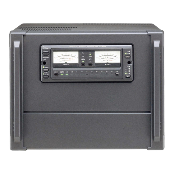
Hf/50 mhz all band 1 kw linear amplifier
Hide thumbs
Also See for IC-PW1:
- Service manual addendum (201 pages) ,
- Service manual (178 pages) ,
- Instruction manual (20 pages)
Table of Contents
Advertisement
Quick Links
Advertisement
Table of Contents

Subscribe to Our Youtube Channel
Related Manuals for Icom IC-PW1


Summary of Contents for Icom IC-PW1
- Page 1 INSTRUCTION MANUAL HF/50 MHz ALL BAND 1 kW LINEAR AMPLIFIER iPW1 iPW1EURO...
-
Page 2: Important
[ALC adj1] and [ALC adj2] pots properly on the rear panel of the linear amplifier. Icom, Icom Inc. and the are registered trademarks of Icom Incorporated (Japan) in the United States, the United Kingdom, Germany, France, Spain, Russia and/or other countries. -
Page 3: Table Of Contents
I Grounding ............6 I Antenna ............6 ABOUT CE ..........20 SUPPLIED ACCESSORIES Accessories included with the IC-PW1/EURO: Qty. q Accessory cable (OPC-104B) ......1 w Coaxial cable (OPC-125B) ........1 e Separation cable (OPC-730) ....... 1 r Remote control (CI-V) cable (OPC-718) ....1 t Remote controller feet ......... -
Page 4: Panel Description
PANEL DESCRIPTION I Front panel and remote controller HF/50MHz ALL BAND 1kW LINEAR AMPLIFIER POWER 1.5K 20 30 40 INPUT TRANSMIT ∞ ALC ad j TEMP TEMP METER-1 METER-2 TUNER DOWN AUTO AMP/ PROTECT HF/50MHz ALL BAND 1kW LINEAR AMPLIFIER POWER 1.5K 20 30 40... - Page 5 (p. 17) - When the linear amplifier is OFF, the [AMP/PROTECT] does not light and the exciter’s signal is applied to one of the output connectors or the IC-PW1/EURO’s anten- na tuner. y LOWER BAND SELECTOR [DOWN] (p. 16)
-
Page 6: I Rear Panel
[ALC adj2] pots properly. This may damage the final r ALC OUTPUT JACKS [ALC1]/[ALC2] (p. 12) FETs. Connect to the ALC input jack of a non-Icom exciter i CIRCUIT BREAKERS (p. 17) (transceiver). Cut off the AC input when over current occurs. -
Page 7: Panel Description
Sets the connected exciter number. Accept a 50 Ω antenna with a PL-259 connector. - Select [1] when 1 exciter is connected. [ACC-2] outputs the received [ACC-1] signal to another Icom option such as the EX-627 AUTOMATIC ANTENNA SELECTOR - Select [1&2] when 2 exciters or 1 exciter with 2 speci- fied band antenna connectors is connected. -
Page 8: Installation And Connections
IC-PW1/EURO, see SUP- PLIED ACCESSORIES on p. ii of this manual. The IC-PW1/EURO can accept either 100–120 V AC or 200–240 V AC power.* However, we recommend using 200–240 V AC rather than 100–120 V AC for I Ferrite core installation better power supply efficiency and longer periods of... -
Page 9: I Grounding
Low SWR allows full power for transmitting even when using the antenna When using 1 antenna, use the [ANT1] connector. tuner. The IC-PW1/EURO has an SWR meter to CAUTION: Protect your linear amplifier from monitor the antenna SWR continuously. -
Page 10: I System Interconnections
INSTALLATION AND CONNECTIONS I System interconnections 1 or 2 Icom 100 W HF transceivers can be connected See the following diagrams for making connections as exciters to the IC-PW1/EURO. Non-Icom trans- between the IC-PW1/EURO and an exciter (transceiv- ceivers can be used, however, band selection will not er). - Page 11 Ground AC outlet (IC-PW1 : 100–120/220–240 V IC-PW1EURO : 230 V) • Using 2 Icom exciters (transceivers) The following connections also apply to trans- ceivers having multiple antenna connectors for specified bands (e.g. IC-726, IC-729, etc.) Remote control cable (supplied)
- Page 12 Non-Icom exciter (IC-PW1 : 100–120/220–240 V IC-PW1EURO : 230 V) • Using 1 Icom and 1 non-Icom exciters NOTE: The specifications for the SEND relay are 5 V DC 0.1 A. If this level is exceeded, a large (transceivers) external relay must be used.
-
Page 13: Installation And Connections
• Jumper location of controller These diagrams show the factory defaults. NOTE: When using the antenna selector of the IC-PW1/EURO while the power is OFF, as above, tuner intial- ization of the IC-PW1/EURO may not be performed correctly if the applied voltage is insufficient. -
Page 14: I Separating The Remote Controller
INSTALLATION AND CONNECTIONS I Separating the remote controller y Replace the control cable with the supplied sepa- The control section of the linear amplifier can be sep- arated from the main body, doubling as a remote con- ration cable through the cable hole. Use the short- troller. -
Page 15: Operation
I When first applying power (CPU resetting) Before first applying power, make sure all connec- If the controller’s power is supplied from non-Icom tions required for your system are complete by refer- exciters or auxiliary power supply (p. 10), turn the ring to chapter 2. -
Page 16: I Programming The Ci-V Address
- Refer to the instruction manual for details. - The band indicators, [1.8]–[50], light continuously. - When using the same baud rate, the exciters’ fre- r Rotate the 1st Icom exciter’s tuning dial until the quencies are synchronized. [INPUT z] light continuously lights. -
Page 17: I Initial Settings For Ci-V Remote Control Operation
‘ Initial settings for CI-V remote control operation Before setting the remote control operation, refer to the following operating procedure. ï ï When using one (1) Icom exciter with one (1) ï ï When using two (2) Icom exciters; ANT line;... - Page 18 OPERATION ‘ Initial settings for CI-V remote control operation (continued) t Push [DOWN] to turn the position memory function ï ï When using one (1) Icom and one (1) non- for the [INPUT] select switch ON. Icom exciter; • The band indicators, [1.8]–[50], light continuously.
-
Page 19: I Operation
METER-1 METER-2 antenna tuner and linear amplifier according to the TUNER DOWN AUTO operating band when at least 1 Icom exciter is con- AMP/ PROTECT nected to the [INPUT1] connector. [AMP/PROTECT] [TUNER] The set conditions may not be stored when the lin- ear amplifier is turned OFF immediately after set-... -
Page 20: I Antenna Tuner Operation
OPERATION I Antenna tuner operation The built-in automatic antenna tuner can match the This antenna tuner is also used when the linear antenna feed line impedance to 50 Ω when the feed amplifier is turned OFF. line impedance is within 16.7 to 150 Ω for HF bands ➥... -
Page 21: Maintenance
The following chart is designed to help you correct If you are unable to locate the cause of a problem or problems which are not equipment malfunctions. solve it through the use of this chart, contact your nearest Icom Dealer or Service Center. PROBLEM POSSIBLE CAUSE SOLUTION REF. -
Page 22: Specifications
( ⁄ ") DECLARATION OF CONFORMITY We Icom Inc. Japan 1-1-32, Kamiminami, Hirano-ku Osaka 547-0003, Japan Declare on our sole responsibility that this equipment complies with the essential requirements of the Radio and Telecommunications Terminal Equipment Directive, 1999/5/EC, and that any applicable Essential Test Düsseldorf 1st Dec. -
Page 23: About Ce
SPECIFICATIONS INSTALLATION NOTES For amateur base station installations it is recom- EIRP clearance heights by frequency band mended that the forwards clearance in front of the an- 1 Watts 2.1 m tenna array is calculated relative to the EIRP (Effective 10 Watts 2.8 m Isotropic Radiated Power). - Page 24 A-5449G-1EX-r Printed in Japan © 1997–2007 Icom Inc. 1-1-32 Kamiminami, Hirano-ku, Osaka 547-0003, Japan Printed on recycled paper with soy ink.
Need help?
Do you have a question about the IC-PW1 and is the answer not in the manual?
Questions and answers