
Related Manuals for Honda EM3800SX


Summary of Contents for Honda EM3800SX
- Page 1 EM3800SX•EM5000SX•EM6500SX See page 60 for instructions on assembling your generator.
- Page 2 The engine exhaust from this product contains chemicals known to the State of California to cause cancer, birth defects or other reproductive harm. Exhaust contains poisonous carbon monoxide gas that can build up to dangerous levels in closed areas. Breathing carbon monoxide can cause unconsciousness or death. Never run the generator in a closed, or even partly closed area where people may be present.
- Page 3 Congratulations on your selection of a Honda generator. We are certain you will be pleased with your purchase of one of the finest generators on the market. We want to help you get the best results from your new generator and to operate it safely.
- Page 4 A FEW WORDS ABOUT SAFETY Your safety and the safety of others are very important. And using this generator safely is an important responsibility. To help you make informed decisions about safety, we have provided operating procedures and other information on labels and in this manual.
-
Page 5: Table Of Contents
CONTENTS GENERATOR SAFETY ................Safety Label Locations ............... Important Safety Information ............COMPONENT IDENTIFICATION .............. CONTROLS ....................10 Engine Switch ..................10 Starter Grip ..................10 Fuel Valve Lever ................. 11 Choke Rod ................... 11 Voltage Selector Switch (Dual Voltage System) ...... - Page 6 MAINTENANCE ..................35 The Importance of Maintenance ............35 Maintenance Safety ................36 Maintenance Schedule ..............37 Engine Oil Change ................38 Air Cleaner Service ................39 Fuel Sediment Cup Cleaning ............40 Spark Plug Service ................
-
Page 7: Generator Safety
GENERATOR SAFETY SAFETY LABEL LOCATIONS These labels warn you of potential hazards that can cause serious injury. Read them carefully. If a label comes off or becomes hard to read, contact your Honda generator dealer for a replacement. Non-California type California type... -
Page 8: Important Safety Information
IMPORTANT SAFETY INFORMATION Honda generators are designed to give safe and dependable service if operated according to instructions. Read and understand this owner’s manual before operating your generator. You can help prevent accidents by being familiar with your generator’s controls and by observing safe operating procedures. - Page 9 Electric Shock Hazards The generator produces enough electric power to cause a serious shock or electrocution if misused. Using a generator or electrical appliance in wet conditions, such as rain or snow, or near a pool or sprinkler system, or when your hands are wet, could result in electrocution.
-
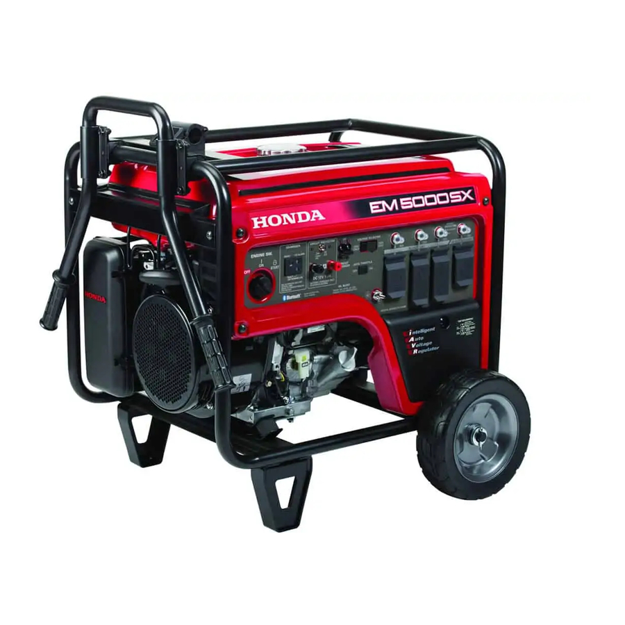
Page 10: Component Identification
COMPONENT IDENTIFICATION ENGINE SWITCH CONTROL PANEL CHOKE ROD AIR CLEANER FUEL VALVE LEVER STARTER GRIP OIL FILLER CAP/DIPSTICK ENGINE SERIAL NUMBER FUSE OIL DRAIN PLUG CONTROL PANEL 1:Except EM3800SX 120 ONLY 120/240 VOLTAGE SELECTOR SWITCH AC CIRCUIT PROTECTORS AC CIRCUIT BREAKER 120/240V AC RECEPTACLE DC CIRCUIT... - Page 11 TRANSPORT HANDLE FUEL TANK CAP FUEL GAUGE SPARK PLUG CAP FRAME SERIAL NUMBER STAND WHEEL MUFFLER Record the engine and frame serial numbers and date of purchase for your future reference. Refer to these serial numbers when ordering parts and when making technical or warranty inquiries (see page Engine serial number: Frame serial number:...
-
Page 12: Controls
CONTROLS Engine Switch To start and stop the engine. Key position: OFF: To stop the engine. Key can be removed/inserted. To run the engine after starting. START: To start the engine by operating the starter motor. ENGINE SWITCH Starter Grip To start the engine, pull the starter grip lightly until resistance is felt, and then pull briskly. -
Page 13: Fuel Valve Lever
Fuel Valve Lever The fuel valve is located between the fuel tank and carburetor. When the valve lever is in the ON position, fuel is allowed to flow from the fuel tank to the carburetor. Be sure to return the fuel valve lever to the OFF position after stopping the engine. -
Page 14: Voltage Selector Switch (Dual Voltage System)
Voltage Selector Switch (Dual Voltage System) The voltage selector switch switches the main power carrying windings of the generator to produce ‘‘120V ONLY’’ or ‘‘120/240V’’. If a 240V appliance is connected to the 4-prong receptacle, the switch must be in the ‘‘120/240V’’ position. If only a 120V appliance is being connected to any of the 120V 3-prong receptacles, select the ‘‘120V ONLY’’... -
Page 15: Dc Terminals
DC Terminals The DC terminals may ONLY be used for charging 12-volt automotive type batteries. The terminals are colored red to identify the positive ( ) terminal and black to identify the negative ( ) terminal. The battery must be connected to the generator DC terminals with the proper polarity (battery positive to generator red terminal and battery negative to the generator black terminal). -
Page 16: Oil Alert System
Oil Alert System The Oil Alert system is designed to prevent engine damage caused by an insufficient amount of oil in the crankcase. Before the oil level in the crankcase can fall below a safe limit, the Oil Alert system will automatically stop the engine (the engine switch will remain in the ON position). -
Page 17: Ac Circuit Breaker
AC Circuit Breaker The AC circuit breaker will automatically switch OFF if there is a short circuit or a significant overload of the generator at the receptacle. If the AC circuit breaker is switched OFF automatically, check that the appliance is working properly and does not exceed the rated load capacity of the circuit before switching the AC circuit breaker ON again. -
Page 18: Ac Circuit Protector
AC Circuit Protector The AC circuit protectors will automatically switch OFF if there is a short circuit or a significant overload of the generator at the 20A 120V, 30A 120V locking plug, or 120/240V locking plug receptacle. If an AC circuit protector switches OFF automatically, check that the appliance is working properly and does not exceed the rated load capacity of the circuit before resetting the AC circuit protector ON. -
Page 19: Generator Use
GENERATOR USE Connections to a Building’s Electrical System Connections for standby power to a building’s electrical system must be made by a qualified electrician. The connection must isolate the generator power from utility power, and must comply with all applicable laws and electrical codes. A transfer switch, which isolates generator power from utility power, is available through authorized Honda generator dealers. -
Page 20: Ac Applications
AC Applications Before connecting an appliance or power cord to the generator: Make sure that it is in good working order. Faulty appliances or power cords can create a potential for electrical shock. If an appliance begins to operate abnormally, becomes sluggish, or stops suddenly, turn it off immediately. -
Page 21: Ac Operation
AC Operation Start the engine (see page Turn the voltage selector switch to either position. With the voltage selector switch in the ‘‘120/240V’’ position, you can use the 120V and 120/240V receptacles simultaneously. If you are NOT using the 120/240V receptacle, then select the ‘‘120V ONLY’’ position. -
Page 22: Ac Receptacle Selection
AC Receptacle Selection The control panel, shown below, has a voltage selector switch and four receptacles. Receptacle 4, the 240-volt receptacle, has two powered terminals, 4A and 4B. EM3800SX: 120V 30A 120V 20A (in total) 120V 20A (in total) & 120/240V 20A Power Producing Circuits This generator is equipped with two power generating circuits. - Page 23 Voltage Selector Switch The power available to each receptacle depends on the position of the voltage selector switch. Switch Position Receptacle Available Power 120V ONLY 27.5A at 120V 20A at 120V 20A at 120V 20A at 120V None 120V/240V 13.8A at 120V 13.8A at 120V 13.8A at 120V 4A-4B...
- Page 24 The control panel, shown below, has a voltage selector switch and four receptacles. Receptacle 4, the 240-volt receptacle, has two powered terminals, 4A and 4B. EM5000SX: 120V 30A 120V 20A (in total) 120V 20A (in total) & 120/240V 30A Power Producing Circuits This generator is equipped with two power generating circuits.
- Page 25 Voltage Selector Switch The power available to each receptacle depends on the position of the voltage selector switch. Switch Position Receptacle Available Power 120V ONLY 30A at 120V 20A at 120V 20A at 120V 30A at 120V None 120V/240V 18.8A at 120V 18.8A at 120V 18.8A at 120V 4A-4B...
- Page 26 The control panel, shown below, has a voltage selector switch and four receptacles. Receptacle 4, the 240-volt receptacle, has two powered terminals, 4A and 4B. EM6500SX: 120V 30A 120V 20A (in total) 120V 20A (in total) & 120/240V 30A Power Producing Circuits This generator is equipped with two power generating circuits.
- Page 27 Voltage Selector Switch The power available to each receptacle depends on the position of the voltage selector switch. Switch Position Receptacle Available Power 120V ONLY 30A at 120V 20A at 120V 20A at 120V 30A at 120V None 120V/240V 22.9A at 120V 20A at 120V 20A at 120V 4A-4B...
-
Page 28: Dc Operation
DC Operation The DC terminals may ONLY be used for charging 12-volt automotive type batteries. Connecting the battery charging cables: Before connecting the battery charging cables to a battery that is installed in a vehicle, disconnect the vehicle ground battery cable from the battery negative ( ) terminal. - Page 29 An overloaded DC circuit, excessive current draw by the battery, or a wiring problem will trip the DC circuit protector (PUSH button extends out). If this happens, wait a few minutes before pushing in the circuit protector to resume operation. If the DC circuit protector continues to go OFF, discontinue charging and see your authorized Honda generator dealer.
-
Page 30: Auto Throttle System
Auto Throttle System With the switch in the AUTO position, engine speed is automatically reduced when ALL loads are turned OFF or disconnected. When appliances are turned ON or reconnected, the engine returns to rated speed. In the OFF position, the Auto Throttle system does not operate. The Auto Throttle system will not respond to electrical loads of less than 1 ampere or intermittent loads such as a staple gun. -
Page 31: High Altitude Operation
High Altitude Operation At high altitude, the standard carburetor air/fuel mixture will be too rich. Performance will decrease, and fuel consumption will increase. A very rich mixture will also foul the spark plug and cause hard starting. Operation at an altitude that differs from that at which this engine was certified, for extended periods of time, may increase emissions. -
Page 32: Pre-Operation Check
PRE-OPERATION CHECK Engine Oil Check the oil level BEFORE EACH USE with the generator on a level surface and the engine stopped. Use 4-stroke motor oil that m e e t s o r e x c e e d s t h e requirements for API service c a t e g o r y S J o r l a t e r ( o r equivalent). -
Page 33: Refueling
Refueling With the engine stopped, check the fuel level gauge. Refill the fuel tank if the fuel level is low. Gasoline is highly flammable and explosive. You can be burned or seriously injured when handling fuel. Stop engine and keep heat, sparks, and flame away. Refuel only outdoors. -
Page 34: Fuel Recommendations
Fuel can damage paint and plastic. Be careful not to spill fuel when filling your fuel tank. Damage caused by spilled fuel is not covered under warranty. After refueling, reinstall the fuel tank cap securely. Fuel Recommendations This engine is certified to operate on regular unleaded gasoline with a pump octane rating of 86 or higher. -
Page 35: Starting The Engine/Stopping The Engine
STARTING THE ENGINE/STOPPING THE ENGINE Starting the Engine For your safety, do not operate the generator in an enclosed area such as a garage. Your generator’s exhaust contains poisonous carbon monoxide gas that can collect rapidly in an enclosed area and cause illness or death. - Page 36 With electric starter: Connect the battery cables to the generator. (page Turn the engine switch to the START position and hold it there for 5 seconds or until the engine starts. Operating the starter motor for more than 5 seconds can damage the motor.
-
Page 37: Maintenance
MAINTENANCE The Importance of Maintenance Good maintenance is essential for safe, economical, and trouble free operation. It will also help reduce air pollution. Improper maintenance, or failure to correct a problem before operation, can cause a malfunction in which you can be seriously hurt or killed. -
Page 38: Maintenance Safety
Maintenance Safety Some of the most important safety precautions follow. However, we cannot warn you of every conceivable hazard that can arise in performing maintenance. Only you can decide whether or not you should perform a given task. Failure to properly follow maintenance instructions and precautions can cause you to be seriously hurt or killed. -
Page 39: Maintenance Schedule
Maintenance Schedule REGULAR SERVICE PERIOD (3) First Every Every Every ITEM Each month 3 months 6 months year Performed at every indicated month or operating hour interval, 20 Hrs. 50 Hrs. 100 Hrs. 300 Hrs. whichever comes first. Engine oil Check level Change Air cleaner... -
Page 40: Engine Oil Change
Engine Oil Change Drain the oil while the engine is warm to assure rapid and complete draining. Place a suitable container below the engine to catch the oil, then remove the oil drain plug and sealing washer, remove the oil filler cap/dipstick, and drain the oil. -
Page 41: Air Cleaner Service
Air Cleaner Service A dirty air cleaner will restrict air flow to the carburetor. To prevent carburetor malfunction, service the air cleaner regularly. Service more frequently when operating the generator in extremely dusty areas. Operating the engine without an air filter or with a damaged air filter will allow dirt to enter the engine, causing rapid engine wear. -
Page 42: Fuel Sediment Cup Cleaning
Fuel Sediment Cup Cleaning The sediment cup prevents dirt or water that may be in the fuel tank from entering the carburetor. If the engine has not been run for a long time, the sediment cup should be cleaned. Turn the fuel valve lever to the OFF position. Remove the sediment cup, O-ring, and filter. -
Page 43: Spark Plug Service
Spark Plug Service In order to service the spark plug, you will need a spark plug wrench (commercially available). Recommended spark plugs: BPR5ES (NGK) W16EPR-U (DENSO) To ensure proper engine operation, the spark plug must be properly gapped and free of deposits. An incorrect spark plug can cause engine damage. -
Page 44: Spark Arrester Maintenance
Check that the spark plug sealing washer is in good condition, and thread the spark plug in by hand to prevent cross-threading. After the spark plug is seated, tighten with a spark plug wrench to compress the washer. If installing a new spark plug, tighten 1/2 turn after the spark plug seats to compress the washer. -
Page 45: Fuse Replacement
Fuse Replacement If the fuse is blown, the starter motor won’t operate. Turn the engine switch to the OFF position. Remove the fuse holder cover and replace the fuse. The specified fuse is 10A. FUSE HOLDER If frequent fuse failure occurs, determine the cause and correct the problem before attempting to operate the generator further. -
Page 46: Storage
STORAGE Storage Preparation Proper storage preparation is essential for keeping your generator trouble-free and looking good. The following steps will help to keep rust and corrosion from impairing your generator’s function and appearance, and will make the engine easier to start when you use the generator again. - Page 47 Service according to the table below: STORAGE TIME RECOMMENDED SERVICE PROCEDURE TO PREVENT HARD STARTING Less than 1 month No preparation required 1 to 2 months Fill with fresh gasoline and add gasoline stabilizer *. Fill with fresh gasoline and add gasoline 2 months to 1 year stabilizer *.
- Page 48 Draining the Fuel Tank and Carburetor Gasoline is highly flammable and explosive. You can be burned or seriously injured when handling fuel. Stop the engine and keep heat, sparks, and flame away. Handle fuel only outdoors. Wipe up spills immediately. Drain the carburetor by loosening the drain screw.
-
Page 49: Engine Oil
Engine Oil Change the engine oil (see page Remove the spark plug (see page Pour a teaspoon (5 10 cc) of clean engine oil into the cylinder. Pull the starter grip several times to distribute the oil in the cylinder. Reinstall the spark plug. -
Page 50: Storage Precautions
Storage Precautions If your generator will be stored with gasoline in the fuel tank and carburetor, it is important to reduce the hazard of gasoline vapor ignition. Select a well ventilated storage area away from any appliance that operates with a flame, such as a furnace, water heater, or clothes dryer. Also avoid any area with a spark-producing electric motor, or where power tools are operated. -
Page 51: Transporting
TRANSPORTING When transporting the generator, turn the engine switch and the fuel valve OFF. Keep the generator level to prevent fuel spillage. Fuel vapor or spilled fuel may ignite. Contact with a hot engine or exhaust system can cause serious burns or fires. -
Page 52: Troubleshooting
TROUBLESHOOTING When the engine will not start: Is there fuel in the Refill the fuel tank tank? (page 31). Is there enough oil Add the recom- in the engine? mended oil (page 30). Is the spark plug in Readjust gap and good condition? dry the spark plug. - Page 53 No electricity at the AC receptacles: Is the AC circuit breaker Turn the AC circuit breaker ON (page 15). NO DEFECTS Check the electrical ap- Take the generator to an pliance or equipment for authorized Honda generator any defects. dealer. Replace the electrical ap- pliance or equipment.
-
Page 54: Technical Information
TECHNICAL INFORMATION Emission Control System Information Source of Emissions The combustion process produces carbon monoxide, oxides of nitrogen, and hydrocarbons. Control of hydrocarbons and oxides of nitrogen are very important because, under certain conditions, they react to form photochemical smog when subjected to sunlight. Carbon monoxide does not react in the same way, but it is toxic. - Page 55 Problems That May Affect Emissions If you are aware of any of the following symptoms, have your engine inspected and repaired by your servicing dealer. Hard starting or stalling after starting. Rough idle. Misfiring or backfiring under load. Afterburning (backfiring). Black exhaust smoke or high fuel consumption.
-
Page 56: Air Index
Air Index (Models certified for sale in California) An Air Index Information label is applied to engines certified to an emission durability time period in accordance with the requirements of the California Air Resources Board. The bar graph is intended to provide you, our customer, the ability to compare the emissions performance of available engines. -
Page 57: Wiring Diagram
WIRING DIAGRAM EM3800SX... - Page 58 EM5000SX, EM6500SX...
-
Page 59: Specifications
SPECIFICATIONS Dimensions Model EM3800SX Type California type Non-California type (AC type) (AN type) Description code EAMC Length 40.9 in (1,040 mm) Width 27.2 in (691 mm) Height 28.4 in (721 mm) Dry mass [weight] 193.1 lbs (87.6 kg) 192.0 lbs (87.1 kg) Engine Model GX240... - Page 60 Dimensions Model EM5000SX Type California type Non-California type (AC, ACH type) (AN, ANH type) Description code EANC Length 41.3 in (1,049 mm) Width 27.2 in (691 mm) Height 28.4 in (721 mm) Dry mass [weight] 222.9 lbs (101.1 kg) 221.8 lbs (100.6 kg) Engine Model GX340...
- Page 61 Dimensions Model EM6500SX Type California type Non-California type (AC, ACH type) (AN, ANH type) Description code EAPC Length 41.9 in (1,064 mm) Width 27.2 in (691 mm) Height 28.4 in (721 mm) Dry mass [weight] 228.4 lbs (103.6 kg) 227.3 lbs (103.1 kg) Engine Model GX390...
-
Page 62: Assembly
ASSEMBLY The Importance of Proper Assembly Proper assembly is essential to operator safety and the reliability of the machine. Any error or oversight made by the person assembling and servicing a unit can easily result in faulty operation, damage to the machine, or injury to the operator. - Page 63 Important Safety Precautions Make sure you have a clear understanding of all basic shop safety practices and that you are wearing appropriate clothing and safety equipment. When performing this assembly, be especially careful of the following: Read the instructions before you begin, and be sure you have the tools and skills required to perform the tasks safely.
- Page 64 Unpacking Remove the generator and loose parts box from the carton. Compare the loose parts with the inventory list below. Tools Required: 12 mm wrench (2), pliers Loose Parts (Wheel kit and handle) Check all loose parts against the following list. Contact your dealer if any of the loose parts shown below are not included with your generator.
- Page 65 Handle Installation Install the right and left handles on the generator upper frame using the handle brackets and four flange bolts. TORQUE: 17 22 lbf·ft (24 29 N·m , 2.4 3.0 kgf·m) 8 16 mm FLANGE BOLT (4) RIGHT UPPER HANDLE ASSY LEFT UPPER HANDLE ASSY RIGHT HANDLE BRACKET...
- Page 66 Wheel Kit Installation Apply grease to the axle shaft as shown below, and install the two wheels on the axle shaft using the washers and split pins. Install the axle assembly on the generator using four 8 16 mm flange bolts and 8 mm flange nuts. Install the two stands on the under frame using four 8 16 mm flange bolts.
- Page 67 Hanger Kit Installation (optional) Position the hanger at the generator’s balance point as shown below. Fit the end tabs of the hanger through the bracket slots, and bolt the brackets to the hanger and tighten securely. TORQUE: 17 22 lbf·ft (24 29 N·m , 2.4 3.0 kgf·m) 8 16 mm FLANGE BOLT (4) HANGER HANGER BRACKET (2)
- Page 68 Remote Control Kit (optional) Remove the blind 6-P connector from the back of the control panel. Connect the remote control cable to the back of the control panel and remote control box. Install the two cable ties as shown. REMOTE CONTROL CABLE CABLE TIES REMOTE CONTROL...
- Page 69 Remote Control Box PILOT LAMP START BUTTON STOP BUTTON Starting the engine with remote control Turn the fuel valve on the generator to the ON position. Turn the Auto Throttle switch on the generator to the OFF position. Turn the engine switch on the generator to the ON position. Press the start button until engine starts and the pilot lamp comes Stopping the engine with remote control Press the stop button.
- Page 70 Battery Tray Kit (optional) Follow the instructions that come with the battery tray kit and install the kit on the generator frame. Route the starter cable under the tank and connect it to the starter solenoid. Connect the ground cable to the generator rear housing. Set the battery on the battery tray and secure with the battery bracket.
- Page 71 CABLE TIE STARTER SOLENOID STARTER CABLE (positive) GROUND CABLE STARTER GROUND CABLE CABLE CABLE BATTERY BRACKET BATTERY Use a battery rated at BATTERY GUARD BATTERY GUARD BATTERY TRAY BATTERY GUARD PLATE...
- Page 72 Engine Oil The generator is shipped WITHOUT OIL in the engine. Place the generator on a level surface. Add enough of the recommended oil to bring the oil level to the top of the oil filler neck. AMBIENT TEMPERATURE Use a 4-stroke motor oil that meets the requirements for API service category SJ or OIL FILLER HOLE...
- Page 73 BEFORE OPERATION Before using your generator, you should become familiar with information contained in the following chapters and sections: GENERATOR SAFETY (page CONTROLS (page GENERATOR USE (page STARTING THE ENGINE (page STOPPING THE ENGINE (page...
-
Page 74: Warranty Service Information
General Manager can help. Almost all problems are solved in this way. If you are dissatisfied with the decision made by the dealership’s management, contact the Honda Power Equipment Customer Relations Office. You can write to: American Honda Motor Co., Inc. -
Page 75: Honda Publications
292-5395 or visit www.hondapowerequipment.com Parts Catalog This manual provides complete, illustrated parts lists. Available through your Honda dealer. Accessories Catalog Your authorized Honda power equipment dealer offers a wide selection of accessories (optional equipment) to make your generator even more useful. Visit www.hondapowerequipment.com... -
Page 76: Index
INDEX ASSEMBLY ....................60 COMPONENT IDENTIFICATION .............. CONTENTS ....................CONTROLS ....................10 AC Circuit Breaker ................15 AC Circuit Protector ................16 Auto Throttle System ............... 14 Choke Rod ................... 11 DC Circuit Protector ................ - Page 77 PRE-OPERATION CHECK ............... . 30 Engine Oil ................... 30 Fuel Recommendations ..............32 Refueling .................... . 31 SPECIFICATIONS ..................57 STARTING THE ENGINE/STOPPING THE ENGINE ....... 33 STORAGE ....................44 Storage Precautions ................48 Storage Preparation ................
- Page 78 MEMO...
- Page 79 K2:EM5000SX 00X31-Z21-6050...
Need help?
Do you have a question about the EM3800SX and is the answer not in the manual?
Questions and answers