Grizzly G8689 Owner's Manual
Mini mill
Hide thumbs
Also See for G8689:
- Parts breakdown (5 pages) ,
- Instruction manual (44 pages) ,
- Owner's manual (44 pages)

Related Manuals for Grizzly G8689


Summary of Contents for Grizzly G8689
- Page 1 MODEL G8689 MINI MILL OWNER'S MANUAL WARNING: NO PORTION OF THIS MANUAL MAY BE REPRODUCED IN ANY SHAPE OR FORM WITHOUT THE WRITTEN APPROVAL OF GRIZZLY INDUSTRIAL, INC.
-
Page 3: Table Of Contents
Table of Contents INTRODUCTION ..........2 SECTION 5: ACCESSORIES ......24 SECTION 6: MAINTENANCE ......27 SECTION 1: SAFETY ........6 SECTION 7: SERVICE ........29 SECTION 2: CIRCUIT REQUIREMENTS ..10 SECTION 3: SET UP ........11 WARRANTY AND RETURNS ......41 SECTION 4: OPERATIONS ...... -
Page 4: Introduction
INTRODUCTION Manual Accuracy Contact Info your machine may not exactly match the manual Machine Description www.grizzly.com... -
Page 5: Machine Data Sheet
Machine Data Sheet MACHINE DATA SHEET Customer Service #: (570) 546-9663 · To Order Call: (800) 523-4777 · Fax #: (800) 438-5901 MODEL G8689 MINI MILLING MACHINE Product Dimensions: Weight................................101 lbs. Length/Width/Height........................20 x 20 x 30-1/4 in. Foot Print (Length/Width)........................12-1/2 x 8-1/2 in. Shipping Dimensions: Type................................ - Page 6 Table Info Table Length............................15-3/4 in. Table Width............................3-5/8 in. Table Thickness............................. 1-1/4 in. No. Of T Slots..............................2 T Slots Width............................0.465 in. T Slots Height............................5/8 in. T Slots Centers............................1-1/8 in. Stud Size..............................5/8 in. Spindle Info Spindle Taper.............................MT#3 End Milling Cap............................
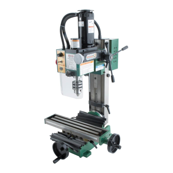
- Page 7 Identification Figure 1.
-
Page 8: Section 1: Safety
SECTION 1: SAFETY For Your Own Safety, Read Instruction Manual Before Operating this Machine The purpose of safety symbols is to attract your attention to possible hazardous conditions. This manual uses a series of symbols and signal words which are intended to convey the level of importance of the safety messages. -
Page 9: Safety Instructions For Machinery
Safety Instructions for Machinery 7. ONLY ALLOW TRAINED AND PROP- 17. REMOVE ADJUSTING KEYS ERLY SUPERVISED PERSONNEL TO WRENCHES. OPERATE MACHINERY. 18. CHECK DAMAGED PARTS 8. KEEP CHILDREN AND VISITORS AWAY. BEFORE USING MACHINERY. 9. MAKE WORKSHOP CHILD PROOF. 19. USE RECOMMENDED ACCESSORIES. 10. - Page 10 Additional Safety Instructions for Mini Mill UNDERSTANDING CONTROLS. 10. MACHINE CARE AND MAINTENANCE. SAFETY ACCESSORIES. 11. DISCONNECT POWER. WORK HOLDING. CHUCK KEY SAFETY 12. AVOIDING ENTANGLEMENT SPINDLE SPEEDS. 13. TOOL HOLDING. POWER DISRUPTION. 14. CLEAN-UP. SPINDLE DIRECTION CHANGES. 15. CUTTING TOOL INSPECTION. STOPPING SPINDLE.
-
Page 11: Glossary Of Terms
Glossary Of Terms VERY Arbor: Facing: Backlash: Feed: Fixture: Collet: Cross Feed: Gib: Cross Slide: Headstock: Cutting Speed: Leadscrew: Dial Indicator: Spindle: Turret: Dividing Head: Ways: Down Milling or Climb Milling: End Mill:... -
Page 12: Section 2: Circuit Requirements
SECTION 2: CIRCUIT REQUIREMENTS Power Connection Device 110V Operation Figure 2 Serious personal injury could occur if you connect the machine to power before com- pleting the setup process. DO NOT connect the machine to the power until instructed later in this manual. Figure 2. -
Page 13: Section 3: Set Up
SECTION 3: SET UP Needed for Set Up This machine presents serious injury hazards to untrained users. Read through this entire manu- al to become familiar with Description the controls and opera- tions before starting the machine! Wear safety glasses dur- ing the entire set up pro- cess! The Model G8689 is a... - Page 14 Bag Contents: (Figure 4) Inventory Box 1: (Figure 3) Figure 3. Figure 4.
- Page 15 Hardware Recognition Chart...
-
Page 16: Site Considerations
Clean Up Site Considerations Workbench Load Figure 5 For optimum performance, clean all moving parts or sliding contact surfaces. Working Clearances Figure 6 Gasoline and petroleum products have low flash points and can explode or cause fire if used to clean machinery. -
Page 17: Mounting To Workbench
Mounting to Installing Handwheel Workbench Handles Components and Hardware Needed: Components and Hardware Needed: Tools Needed: Tools Needed: To attach the handles to the handwheels: To mount the mini mill to the workbench: Note: For the best performance, make sure the cross feed and the longitudinal hand- wheels extend out beyond the edge of the table surface. -
Page 18: Drill Chuck Removal
Drill Chuck Removal NOTICE DO NOT completely unscrew the drawbar before striking it with the hammer. You will damage the threads on the drawbar and the arbor. Tools Needed: Figure 8 To remove the chuck and arbor from the spindle: Figure 8. -
Page 19: Section 4: Operations
OMMEND that you read books, trade maga- zines, or get formal training before begin- ning any projects. Regardless of the con- tent in this section, Grizzly Industrial will not be held liable for accidents caused by lack of training. Note: After using the EMERGENCY STOP Button it will be necessary to reset the SPINDLE ON &... - Page 20 Test Run and Spindle Break-in NOTICE To begin the start up and break-in procedure: DO NOT attempt to change speed ranges with the spindle ON. Damage to the spindle gearing will occur. Lubrication Section 6: MAINTENANCE Page 28. OFF. Figure 11 Steps 4–6 Note: If the lever will not drop into gear at NOTICE...
-
Page 21: Power Shutdown
Power Shutdown Rapid & Micro Downfeed Controls To completely shut the system power OFF: To use the rapid downfeed: OFF. OFF. Figure 13. Note: The EMERGENCY STOP Button is a flap style button that lays over the switch. Closing the flap shuts OFF power to the system. -
Page 22: Table Travel
Limit Block Table Travel Longitudinal Feed: To set the limit block: Figure 15 Cross Feed: Figure 14 Figure 15 Figure 14. Note: The limit block can lose its position after repeated contact with the head. To limit this pos- Figure 15. sibility make sure the head only makes gentle contact with the limit block. -
Page 23: Graduated Dials
Graduated Dials Column Angle Adjustment To adjust the angle: Example: Page 15. Backlash Figure 16 Note: If a high degree of accuracy is required, use additional methods for confirming the angle. A falling head can crush or pinch. Keep the To correct for backlash: head supported when loosening the lock- ing bolt and positioning head. - Page 24 MT#3 Collets To install the MT#3 collet: Figure 17. To remove the collet: Figure 17 Note: Do not overtighten the drawbar. Overtightening makes collet removal difficult Note: When not in use, always remove and causes damage to the drawbar threads, collets and cutting tools from the spindle collet, and the spindle taper.
-
Page 25: Setting Rpm
Setting RPM Cutting Speeds for High Speed Steel (HSS) Cutting Tools To determine the needed RPM: Figure 18 Note: MACHINERY'S HANDBOOK Figure 18 (Cutting Speed x 4) / Tool Diameter = Failure to follow RPM and Feed Rate Guidelines may threaten operator safety from ejected parts or broken tools NOTICE Failure to follow RPM and Feed Rate... -
Page 26: Section 5: Accessories
SECTION 5: ACCESSORIES G7895—Citrus Degreaser G9002—2 ⁄ " Swivel Base Milling Vise G5971 — 3 ⁄ " Swivel Base Milling Vise G5972—4" Swivel Base Milling Vise G5973—5" Swivel Base Milling Vise G5974—6" Swivel Base Milling Vise G5975—8" Swivel Base Milling Vise Figure 19. - Page 27 G9765—9-PC. Ball End Mill Set H3022—Measurement Tool Set Figure 23. Figure 25. ® G9610—Test Indicator G2871—Boeshield T-9 12 oz Spray " " G2870—Boeshield ® T-9 4 oz Spray G9611—Test Indicator G9612—Test Indicator Figure 24. Figure 26.
- Page 28 G7314—700 lb. Capacity Stand H2690—MT#3 Quick Change Collet Set Figure 27. G2861—2 ⁄ " Face Mill G2863 —MT#3 Arbor Figure 29. H5685—4 Rotary Table Figure 28. Figure 30.
-
Page 29: Section 6: Maintenance
SECTION 6: MAINTENANCE Cleaning Always disconnect power to the machine before Cleaning the Model G8689 is relatively easy. performing maintenance. Remove excess cutting fluid and chips, and wipe Failure to do this may off the remaining moisture with a dry cloth. Treat result in serious person- all unpainted cast iron and steel with a non-stain- al injury. - Page 30 Lubrication Figures 31 & 32 Figure 31. Note: You will need to move the covers out of the way to gain access to the A & E lubrication points. Figure 32. NOTICE Lack of lubrication causes poor machine performance. Keep your mill lubricated to reduce wear on parts and discourage oxi- dation..
-
Page 31: Section 7: Service
SECTION 7: SERVICE About Service Troubleshooting page 30... -
Page 32: Adjusting Gibs
Adjusting Gibs Replacing Motor Brushes Tools Needed: To replace the motor brushes: Tools Needed: To adjust the gibs: (see Figure 33) Figure 34. Figure 33. - Page 33 Fuse Replacement Head Counterbalance Spring Tools Needed: To replace the fuse: Figure 35 This spring is under high tension! DO NOT remove the cover or the spring. THE SPRING WILL RAPIDLY UNCOIL CAUSING PERSONAL INJURY. Figure 35.
-
Page 34: Electrical Components
Electrical Components Printed Circuit Board ON/RPM Switch Caution System ON Light Switch Transformer Motor Fuse Power Light E-Stop Button Cooling Figure 36. Figure 38. Figure 37. Figure 39. - Page 35 G8689 Table Assembly Parts Breakdown...
- Page 36 G8689 Parts List PART # DESCRIPTION PART # DESCRIPTION P8689001 BASE P8689048 COOLING FAN P8689002 X-AXIS FEEDING SCREW P8689049 SPINDLE BOX PK37M KEY 4 X 4 X 16 P8689050 PINION P8689004 DIAL PK30M KEY 4 X 4 X 25 P8689005 HANDWHEEL P8689052 BEVEL GEAR...
- Page 37 G8689 Head Assembly -35- G8689 Mini Mill (Mfg. 8/06+)
- Page 38 G8689 Parts List PART # DESCRIPTION PART # DESCRIPTION P8689100 CHIP GUARD P8689145 HIGH/LOW LABEL P8689101 KNURLED SCREW M6-1 X 12 P8689146 MOTOR COVER P8689102 SPACER P8689147 MOTOR FLANGE PSB01M CAP SCREW M6-1 X 16 PS68M PHLP HD SCR M6-1 X 10 PSS02M SET SCREW M6-1 X 6 P8689149...
- Page 39 G8689 Column Assembly...
-
Page 43: Warranty And Returns
WARRANTY AND RETURNS... - Page 44 ® Buy Direct and Save with Grizzly – Trusted, Proven and a Great Value! ~Since 1983~ Visit Our Website Today For Current Specials! ORDER 24 HOURS A DAY! 1-800-523-4777...
Need help?
Do you have a question about the G8689 and is the answer not in the manual?
Questions and answers