Table of Contents
Advertisement
Advertisement
Table of Contents

Subscribe to Our Youtube Channel
Related Manuals for QSC Q-SYS PS-1600


Summary of Contents for QSC Q-SYS PS-1600
- Page 1 Page Stations Networked Page Station User Manual PS‑1600(H/G) – Sixteen-Button Page Station PS‑1650(H/G) – Sixteen Command-Button Page Station PS‑800(H/G) – Eight Command-Button Page Station PS‑400(H/G) – Four Command-Button Page Station TD-000324-00-A *TD-000324-00*...
-
Page 2: Important Safety Precautions And Explanation Of Symbols
IMPORTANT SAFETY PRECAUTIONS AND EXPLANATION OF SYMBOLS WARNING! WARNRNG!: The term “ WARNRNG” indicates instructions regarding personal safety. Nf the instructions are not followed the result may be bodily injury or death. WATNIRG!: The term “ WATNIRG” indicates instructions regarding possible damage to physical equipment. Nf these instructions are not followed, it may result in damage to the equipment that may not be covered under the warranty. -
Page 3: Rohs Statement
RoHS STATEMENT The Q-Sys Page Station products are in compliance with European Directive 2002/95/EC – Restriction of Hazardous Substances (RoHS). The Q-Sys Page Station products are in compliance with “China RoHS” directives. The following chart is provided for product use in China and its territories: Unpacking Package ontents... - Page 4 Introduction Q-Sys is a platform of software and hardware products providing system designers and operators with the tools necessary to design, configure, and manage medium to large scale audio systems. In addition to the primary signal processing and system management components that make up a Q-Sys audio system, the Q-Sys solution includes peripheral components that offer services such as remote management and paging.
- Page 5 If service is required and the original packing material is not available, ensure that the unit is adequately protected for shipment (use a strong box of appropriate size, sufficient packing/padding material to prevent load shifting or impact damage) or call QSC’s Technical Services Group for replacement packing material and a carton.
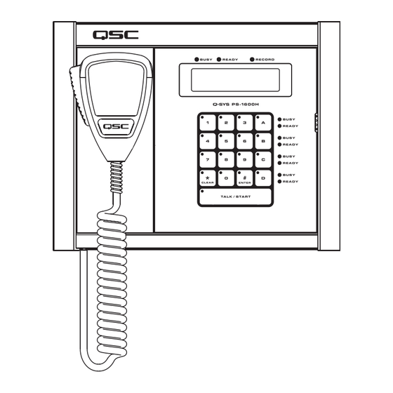
- Page 6 Features Q-Sys PS-1600H Front Panel Refer to Figure 2. To see the keypad configurations of Page Station models PS-1650, PS-800, and PS-400 , see page 15. — Figure 2 — a. LED touch indicators f. Global Busy, Ready and Record Indicators b.
- Page 7 LED Touch Nndicators When a key is pressed, the LED on that key illuminates to indicate that it was pressed. apacitive Touch Keypad • Command buttons can be assigned one of several different types of Commands using the Q-Sys Designer Administration Interface. Once assigned, you just have to press the appropriate Command button to initiate the action.
- Page 8 Q-Sys Page Station Aear Panel Refer to Figure — Figure 3 — a. MIC LINE (In) (three-pin Euro connector) f. Q-Sys LAN B (RJ45 connector) b. AUX POWER (two-pin Euro connector) g. Q-Sys LAN A (RJ45 connector) c. Connector labels h.
-
Page 9: Aux Power
MN /LNRE Nn The Page Station rear panel includes an auxiliary MIC/LINE input for support of a secondary microphone or other audio source. The MIC/LINE accepts a Euro style (Phoenix) three-terminal plug, included in the Page Station package. Follow the Page Station rear panel pin-out labels (Figure 4) for wiring. - Page 10 NPNI onnector The Page Station rear panel includes a six-terminal receptacle (Figure 10, and Figure 12) that provides various GPIO (General Purpose Inputs and Outputs) that allows the Page Station to control or be controlled by a variety of external products. The Page Station GPIO receptacle accepts Euro style (Phoenix) two, three or six-terminal plugs.
- Page 11 • Firmware Version • 2.0.111 • Copyright (C) 2010 • QSC Audio Products, LLC. Aeset the Page Station to Factory Defaults 1. If the Page Station is part of a running design, do the following: a. In Q-Sys Designer, from the main menu, select File > Load from Core and Connect. Select the design containing the Page Station you wish to reset.
- Page 12 4. Insert a reset tool (a paperclip works) into the small hole on the right side of the Page Station to press the reset button. "Clear settings in 10, 9, ..." displays on the Page Station LCD. 5. Hold the reset button until the count down gets to 0. 6.
- Page 13 Mounting tabs on back of Page Station — Figure 16 — 6. Tilt the top of the Page Station back and install the Page Station onto the Mounting Plate by aligning the two tabs on the Page Station with the two slots on the Mounting Plate.
-
Page 14: Specifications
Specifications Hardware Dimensions (H/W/D) 10.37” x 8.3” x 1.5” (263.4 mm x 210.8 mm x 38.1 mm) Line voltage requirements IEEE 802.3af power or +24 VDC/500 mA Accessories included Hardware User Manual, Accessory ship kit, Warranty card Audio Channel Capacity Line Inputs Line Outputs Front Panel Controls... -
Page 15: Keypad Configurations
Keypad Configurations — Figure 17 — — Figure 18 — — Figure 19 — — Figure 20 —... - Page 16 © 2010, QSC Audio Products, LLC. QSC is a registered trademark of QSC Audio Products, LLC. QSC and the QSC logo are registered with the US Patent and Trademark office. Q‑Sys is a trademarks of QSC Audio Products, LLC. Windows is a trademark of Microsoft Corp. All other trademarks are the property of their respective owners.
Need help?
Do you have a question about the Q-SYS PS-1600 and is the answer not in the manual?
Questions and answers