
Summary of Contents for Fluke 54200
- Page 1 ® 54200 TV Signal Generator Users Manual 4822 872 10182 November 1996, Rev. 4 4/98 © 1996 Fluke Corporation, All rights reserved. Printed in the Netherlands. All product names are trademarks of their respective companies.
- Page 3 Fluke's warranty obligation is limited, at Fluke's opinion, to refund of the purchase price, free of charge repair, or replacement of a defective product which is returned to an Fluke authorized service center within the warranty period.
- Page 4 Service Centers To locate an authorized service center, visit us on the World Wide Web: http://www.fluke.com or call Fluke using any of the phone numbers listed below: +1-888-993-5853 in U.S.A. and Canada +31-402-675-200 in Europe +1-425-446-5500 from other countries...
- Page 5 DECLARATION OF CONFORMITY Fluke TV Signal Generator 54200 Manufacturer Fluke Industrial B.V. P.O. Box 90 7600 AB Almelo The Netherlands Statement of Conformity Based on test results using appropriate standards, the product is in conformity with Electromagnetic Compatibility Directive 89/336/EEC...
-
Page 7: Table Of Contents
Title Page Installation and Safety Instructions ........... 1-1 Shipment Note ....................1-5 Initial Inspection....................1-5 Available built-in options Fluke 54200............. 1-5 Introduction...................... 1-9 Safety Instructions.................... 1-9 Maintenance and Repair ................1-9 Grounding (Earthing) ................... 1-9 Power Cable, Line Voltage Range, and Fuses..........1-10 Operating Position of the Instrument .............. - Page 8 54200 Users Manual Aarding ......................1-21 Stroomkabel, netspanningsgebied en zekeringen .......... 1-22 Bedrijfsstand van het toestel ................1-23 Ontstoring radio-interferentie................1-24 Scheidingstransformator ................... 1-24 Inledande anvisningar och säkerhetsanvisningar ..........1-25 Säkerhetsanvisningar ..................1-25 Underhåll och reparation ................1-25 Jordning ....................... 1-25 Nätkabel, nätspänningsområde och säkringar..........
- Page 9 Contents (continued) Description and Applications of the Test Patterns ..........4-40 Circle ......................4-42 Center Cross with Border Castellations ............4-43 Dots ......................4-45 Crosshatch ....................4-46 Checkerboard ....................4-47 White Pattern ....................4-48 Multiburst ....................4-48 Greyscale ..................... 4-49 DEM Pattern ....................
- Page 10 54200 Users Manual Video Recorder Programming by Teletext with PSF ........ 5-7 Contents of Teletext Pages TOP/FLOF ............ 5-9 DIDON ANTIOPE Teletext ................. 5-10 Contents of DIDON ANTIOPE Text Pages ..........5-10 Operating ....................5-12 Checking and Adjusting ................5-13 Wide Screen Signalling (WSS).................
- Page 11 Contents (continued) Remote Control ..................6-1 Introduction...................... 6-3 IEEE-488 Interface ................... 6-3 Instrument Address ..................6-3 Interface Functions..................6-6 RS-232 Interface ....................6-7 Instrument Configuration ................6-7 Interface Functions and Wiring..............6-11 Interface Functions..................6-12 Remote Control Commands ................6-13 Program Message Syntax ................
- Page 12 54200 Users Manual Audio and Euro AV ................. 7-10 BTSC MPX and FM Stereo Pilot ............. 7-10 NICAM Data and NICAM Clock ............. 7-11 Inputs ......................7-11 Audio, Euro AV and MTS Multiplex ............7-11 Mono ......................7-11 Sound Carrier................... 7-11 Modulation ....................
- Page 13 Contents (continued) Teletext, VPS, PDC, and WSS (Digital Services)........8-12 Wide Screen Signalling Bits (WSS ............8-14 TV Standard NTSC ..................8-15 Video Part, using RF Connection ............. 8-15 Video Part, using Y/C Connection (S-VHS, Hi-8)........8-17 Sound Part ....................8-18 Closed Caption (Digital Service CC)............
- Page 15 List of Tables Table Title Page 1-1. Display Indication of built-in Options..............1-8 1-2. Delivered Power Cable ..................1-10 1-3. Cable suministrado ....................1-14 1-4. Cavo di alimentatione fornito in dotazione............1-18 1-5. Meegelverde netkabel ..................1-22 1-6. Medleverera nätkabel................... 1-26 3-1.
- Page 16 Sound Operating Modes (cont) ................5-59 5-18. External Video Modulation Modes ..............5-60 5-19. External Sound Mode ..................5-62 6-1. Fluke 54200 'Status Byte Register'............... 6-14 6-2. Instrument Default Settings after Reset (*RST) ........... 6-17 6-3. Telephone Country Code ..................6-23 6-4.
- Page 17 Installation and Safety Instructions Title Page Shipment Note ....................1-5 Initial Inspection....................1-5 Available built-in options Fluke 54200............. 1-5 Introduction...................... 1-9 Safety Instructions.................... 1-9 Maintenance and Repair ................1-9 Grounding (Earthing) ................... 1-9 Power Cable, Line Voltage Range and Fuses..........1-10 Operating Position of the Instrument ..............
- Page 18 54200 Users Manual Opstellings- en veiligheidsinstructies ............... 1-21 Veiligheidsinstructies..................1-21 Onderhoud en reparatie................1-21 Aarding ....................... 1-21 Stroomkabel, netspanningsgebied en zekeringen.......... 1-22 Bedrijfsstand van het toestel ................1-23 Otnstoring radio-interferentie................1-24 Scheidingstransformator .................. 1-24 Inledande anvisningar och säkerhetsanvisningar..........1-25 Säkerhetsanvisningar ..................1-25 Underhåll och reparation................
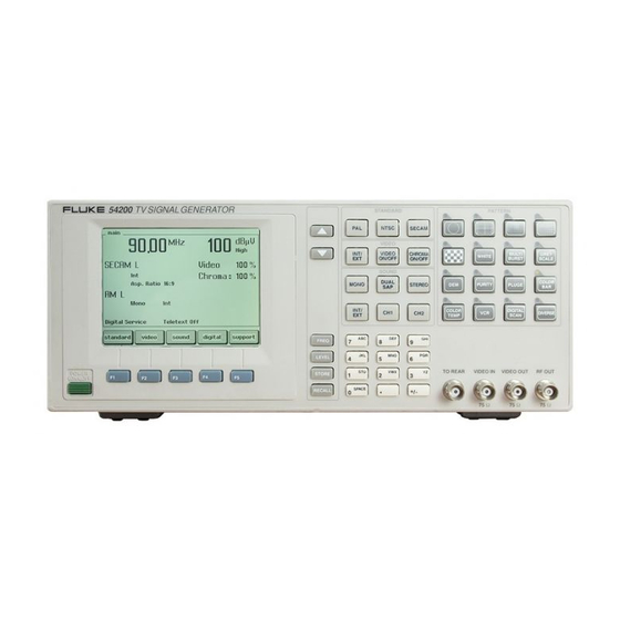
- Page 19 Installation and Safety Instructions Shipment Note Figure 1-1. Front Panel Figure 1-2. Rear Panel...
- Page 20 54200 Users Manual...
-
Page 21: Installation And Safety Instructions
Check that the shipment is complete and note whether any damage has occurred during transport. If the contents are incomplete or there is damage, file a claim with the carrier immediately, and notify the Fluke Sales and Service organization to facilitate the repair or replacement of the instrument. - Page 22 54200 Users Manual The instrument shows the main screen with the current settings: Figure 1-3. Main Screen • Press the softkey (F5). support • The display shows the submenu. support Figure 1-4. Support Submenu • Press the edit softkey (F3). •...
- Page 23 Installation and Safety Instructions Available built-in options Fluke 54200 Figure 1-5. Support System Info Submenu • Press the softkey (F3). view • A popup menu appears, showing the options. Figure 1-6. Popup Menu showing installed Options é ê • Use the or the softkey (F1 or F2) to scroll through the table.
- Page 24 (F5) to return to the submenu. enter support • Press the softkey (F5) again to return to the screen. enter main If you want additional options that are not built-in in your instrument at the moment, please contact you local Fluke Sales Organization.
-
Page 25: Introduction
Installation and Safety Instructions Introduction Introduction This chapter should be read before unpacking, installing, and operating the instrument. It describes grounding, power cables, and fuses. It also contains the Installation and Safety Instructions in the following languages: Spanish, Italian, Dutch and Swedish. Safety Instructions Upon delivery from the factory the instrument complies with the required safety regulations, see Chapter 7. -
Page 26: Power Cable, Line Voltage Range, And Fuses
54200 Users Manual Power Cable, Line Voltage Range, and Fuses Different power cables are available for the local line connectors. On delivery from the factory the instrument is supplied with the ordered power cable: Table 1-2. Delivered Power Cable Type No. Delivered Power Cable 54200/XX1... -
Page 27: Operating Position Of The Instrument
Installation and Safety Instructions Operating Position of the Instrument Operating Position of the Instrument The instrument can be operated on a horizontal surface in a flat position or in a sloping position with the tilting feet folded down. Ensure that the ventilation holes are free of obstruction. - Page 28 54200 Users Manual 1-12...
-
Page 29: Instrucciones De Instalación Y De Seguridad
Installation and Safety Instructions Instrucciones de instalación y de seguridad Instrucciones de instalación y de seguridad Instrucciones de seguridad El aparato sale de fábrica, técnicamente, en perfectas condiciones de seguridad (ver cap. 7). Para que se conserven estas condiciones, y para evitar riesgos en el uso, hay que seguir cuidadosamente las indicaciones siguientes. -
Page 30: Cable De Conducción Eléctrica, Rango De Tensiones De La Linea Y Fusibles
54200 Users Manual Los contactos exteriores de los casquillos BNC tienen el potencial del neutro y están conectados a la carcasa. La puesta a terra a través de los contactos exteriores de los casquillos BNC es inadecuada. Cable de conducción eléctrica, rango de tensiones de la linea y fusibles Existen diferentes cables de conducción eléctrica para los terminales de la conexión a la red. -
Page 31: Posición De Uso Del Instrumento
Installation and Safety Instructions Posición de uso del instrumento Advertencia Asegúrese que el nuevo fusible sea del tipo y de la potencia especificada. El uso de fusibles reparados y/o el cortocircuito de portafusibles está prohibido. No pase por alto esta indicación de seguridad importante. - Page 32 54200 Users Manual 1-16...
-
Page 33: Istruzioni Di Installazione E Di Sicurezza
Installation and Safety Instructions Istruzioni di installazione e di sicurezza Istruzioni di installazione e di sicurezza Istruzioni di sicurezza L'apparecchio viene fornito dalla fabbrica perfettamente sicuro e funzionante dal punto di vista tecnico (vedi Cap. 7). Per preservarlo in condizioni ottimali e garantirne un corretto funzionamento, attenersi scrupolosamente alle seguenti istruzioni. -
Page 34: Cavo Elettrico, Zona Della Tensione Di Rete Et Fusibili
54200 Users Manual Avvertimento E' estremamente pericoloso interrompere il conduttore di protezione interno o esterno all'apparecchio o i contatti di messa a terra. Evitare quindi di farlo intenzionalmente. I contatti esterni delle prese BNC trasferiscono il potenziale del punto neutro del circuito e sono collegate all'incvolucro dell'apparecchio. -
Page 35: Posizione Di Uso Dell'apparecchio
Installation and Safety Instructions Posizione di uso dell’apparecchio Avvertimento Quando si sostituisce un fusibile, l’apparecchio deve essere disinserito da ogni fonte di energia. I fusibili si trovano nel portafusibili sul quadro posteriore del modulo della potenza di entrata. Per sostituire i fusibili del circuito, procedere come segue: •... -
Page 36: Schermatura Contro I Radiodisturbi
54200 Users Manual Schermatura contro i radiodisturbi L'apparecchio è stato realizzato per garantire un funzionamento esente da interferenze. Se viene utilizzato congiuntamente a unità base e unità periferiche non dotate delle stesse protezioni, ne possono derivare interferenze che richiederanno ulteriori intervenu. Trasformatore di separazione Poiché... -
Page 37: Opstellings- En Veiligheidsinstructies
Installation and Safety Instructions Opstellings- en veiligheidsinstructies Opstellings- en veiligheidsinstructies Veiligheidsinstructies Het apparaat heeft de fabriek in een onberispelijke veiligheidstechnische toestand verlaten (zie hoofdstuk 7). Voor het behoud van deze toestand en het risicoloze gebruik dienen de onderstaande instructies nauwkeurig te worden opgevolgd. Onderhoud en reparatie Storingen en uitzonderlijke omstandigheden Wanneer verondersteld moet worden dat een risicoloos gebruik niet meer mogelijk is,... -
Page 38: Stroomkabel, Netspanningsgebied En Zekeringen
54200 Users Manual Waarschuwing Elke onderbreking van de beschermende aardleiding, hetzij binnen of buiten het apparaat, of de scheiding ten opzichte van de aardleiding zijn gevaarlijk. Een opzettelijke onderbreking is verboden. Op de externe contacten van de BNC-bussen is het schakelnulpunt-potentiaal aanwezig. Deze contacten zijn met het huis verbonden. -
Page 39: Bedrijfsstand Van Het Toestel
Installation and Safety Instructions Bedrijfsstand van het toestel Waarschuwing Wanneer een zekering vervangen moet worden, dient het toestel van alle spanningsbronnen te worden losgekoppeld. De zekeringen zitten in de zekeringshouder op het achterpaneel van het ingangsstroom- moduul. Bij het vervangen van de kabelzekeringen als volgt te werk gaan: •... -
Page 40: Ontstoring Radio-Interferentie
54200 Users Manual Ontstoring radio-interferentie Wat radio-ontstoring betreft is het apparaat zorgvuldig ontstoord en gecontroleerd. Bij het schakelen in combinatie met basisunits die niet correct onstoord zijn en met andere perifere apparatuur, kan radiostoring optreden. In de desbetreffende gevallen maakt dit aanvullende maatregelen op radio-ontstoringsgebied noodzakelijk. -
Page 41: Inledande Anvisningar Och Säkerhetsanvisningar
Installation and Safety Instructions Inledande anvisningar och säkerhetsanvisningar Inledande anvisningar och säkerhetsanvisningar Säkerhetsanvisningar Instrumentet har lämnat tillverkningen när det innehållsmässigt var i ett säkerhetstekniskt gott skick (Se kap. 7). För att bibehålla detta skick och en riskfri drift måste man följa nedanstående anvisningar noggrant. -
Page 42: Nätkabel, Nätspänningsområde Och Säkringar
54200 Users Manual Nätkabel, nätspänningsområde och säkringar Det finns nätkablar anpassade till olika länders nätuttag. Instrumentet kan beställas för leverans med en av nedanstående kabeltyper. Table 1-6. Medleverera nätkabel Instrumenttyp Medleverera nätkabel 54200/XX1 Europa 54200/XX3 Nordamerika 54200/XX4 Storbrittannien (U.K.) 54200/XX5 Schweiz 54200/XX8 Australien... -
Page 43: Instrumentets Driftsläge
Installation and Safety Instructions Instrumentets driftsläge Instrumentets driftsläge Instrumentet kan användas horisontalt eller, med fötterna utfällda, i en luttande position. När de nedfällbara fötterna fällts nedåt kan instrumentet användas i ett snedplacerat läge. Den tekniska specifikationen i kapitel 7 är tillämplig för de specificerade användningslägena. - Page 44 54200 Users Manual 1-28...
-
Page 45: Main Features
Chapter 2 Main Features Title Page Introduction...................... 2-3 Main Features....................2-3... -
Page 47: Introduction
SECAM with their subsystems as well as sound standards and data transmission standards. The Fluke 54200 with its menu-driven control makes it easy for you to work with the instrument and allows a large choice and configuration of the provided test signals. The instrument offers the complete RF range from 32 MHz to 900 MHz, so covering the IF-, VHF I-, VHF III-, S-, Hyper- and UHF-Band. - Page 48 Closed Captioning (CC) is a subtitling system which is transmitted using either field of line 21. In the Fluke 54200 Closed Caption and Text Service (T1 to T4) are available for the TV systems NTSC, PAL 625 and 525 line systems, and SECAM.
-
Page 49: Getting Started
Chapter 3 Getting Started Title Page Introduction...................... 3-3 Getting Started ....................3-3 General Information ..................3-3 Turning the Instrument on ................3-3 Self-test Routine....................3-3 Brief Checking Procedure................. 3-4 Test Equipment .................... 3-4 Instrument Settings and Checks..............3-4 Operation and Application................3-13 Control Elements, Display and Connectors........... -
Page 51: Introduction
Getting Started Introduction Introduction This chapter starts with the general procedures and precautions necessary for operation followed by a brief checking procedure. It contains a summary of controls and connectors on the front and rear panels and the display. Getting Started General Information This section outlines the procedure and precautions necessary for operation. -
Page 52: Brief Checking Procedure
54200 Users Manual Brief Checking Procedure This procedure checks the instrument functions with a minimum of steps. It is assumed that the operator doing the test is familiar with the instrument and its specifications. After POWER ON, the instrument is automatically set to the operating mode to which it was set before POWER OFF. - Page 53 Getting Started Brief Checking Procedure • A submenu with the selected country and its default settings appears, in this example, United Kingdom. Figure 3-2. Current Country with Video Standard and Sound System • Press the softkey (F3). edit • A popup menu with a pre-defined country list appears. é...
- Page 54 54200 Users Manual • The display shows the video standard and the sound system according to the selected country. Figure 3-4. Selected Country with Video Standard and Sound System • If your TV equipment does not support the TV system, select the required video é...
- Page 55 Getting Started Brief Checking Procedure The display shows the video submenu with the complete current settings: Figure 3-6. Video Submenu with Current Setting • Press the softkey (F3). edit • A popup menu for numerical entries appears. Figure 3-7. Video Amplitude Setting •...
- Page 56 54200 Users Manual Figure 3-8. Main Menu with changeed Settings • Press the key on the right of the display to select an appropriate RF carrier FREQ frequency, for example, 203.25 MHz. • A popup menu for numerical inputs appears: Figure 3-9.
- Page 57 Getting Started Brief Checking Procedure Figure 3-10. Selected Carrier Frequency • Set your TV to the same frequency or to the corresponding TV channel, in this example channel 9. For the relationship between carrier frequency and TV channel number, see Appendix B. •...
- Page 58 54200 Users Manual Figure 3-12. Final Settings • Press the softkey (F3) to check the sound settings. sound • submenu appears: sound Figure 3-13. Sound Parameter Settings Check if the sound modulation is set to internal ( ) and if an appropriate modulation frequency is selected, for example, If not: CH 1 1.0 kHz .
- Page 59 Getting Started Brief Checking Procedure The popup menu with the selectable modulation frequencies appears: Figure 3-14. Modulation Frequency Setting é ê • Select an appropriate frequency with the softkey (F1 or F2). • Press the softkey (F5) to confirm your selection. enter •...
- Page 60 54200 Users Manual • Connect the RF OUTPUT on the front panel of the 54200 to the antenna input of your TV. Use an appropriate RF connection cable, for example, the attached RF cable BNC to TV. • Check the correct video and sound reproduction on the TV. In this example, you get the following combined test pattern and a mono sound with 1 kHz modulation.
-
Page 61: Operation And Application
Getting Started Operation and Application Operation and Application Control Elements, Display and Connectors The controls and connectors are listed according to their functional sections, and a brief description of each is given. Front Panel Control/connector Function Power switch Five softkeys used to change or select functions or parameters. - Page 62 54200 Users Manual Keys used to select: TV systems PAL, NTSC, or SECAM. Keys used to select: - Internal or external video modulation - Video signal ON/OFF - Chroma signal ON/OFF Keys used to select: - Sound modes MONO, DUAL or SAP, STEREO (SAP = Second Audio Program for BTSC Sound).
-
Page 63: Rear Panel
Getting Started Operation and Application Full graphic display with backlight, 1/4 VGA. Feed through capability from or to the TO FRONT BNC connector at the rear panel. Video input for external CVBS (75 Ω), BNC connector. Video output of CVBS (75 Ω), BNC connector. Radio Frequency output (75 Ω), BNC connector. -
Page 64: Rear Panel
54200 Users Manual Rear Panel Input power module with fuses. For details, see Chapter 1, Power Cable, Line Voltage Range, and Fuses. IEEE-488 bus connector for remote control. RS-232 connector for remote control. R G B output (75 Ω), 3 BNC connectors: Red, Green, and Blue signals. - Page 65 Getting Started Operation and Application Output of NICAM sound (50 Ω), 2 BNC connectors: - DATA = NICAM Data - CLOCK = NICAM Clock MTS IN: MTS multiplex input for the BTSC baseband signal (0.1 MΩ), BNC connector. MTS/PILOT OUT: Output of BTSC baseband signal and output of FM Stereo pilot signal (600 Ω), BNC connector.
- Page 66 54200 Users Manual Audio/Video input, SCART/Euro-AV connector, standard connection for TV and video systems. Table 3-1. EURO AV IN Signal Audio channel 2, right Audio channel 1, left CVBS input 4, 18, 21 Ground Audio/Video output, SCART/Euro-AV connector, standard connection for TV and video systems.
-
Page 67: How To Use The Instrument
Chapter 4 How to Use the Instrument Title Page Introduction...................... 4-3 Operating via Keyboard..................4-3 General Information ..................4-3 Display ....................4-3 Keyboard ....................4-6 Instrument Settings ..................4-7 TV Standard..................... 4-7 Video Settings..................4-10 Sound Settings ..................4-12 Teletext, VPS, PDC, CC, and WSS............4-14 Vision Carrier Frequency Settings (RF Carrier)........ - Page 68 54200 Users Manual DEM 1 (PAL) ..................4-49 DEM 1 (NTSC)..................4-51 DEM 1 (SECAM) ................... 4-52 DEM 2 (PAL) ..................4-53 DEM 2 (NTSC)..................4-53 DEM 2 (SECAM) ................... 4-54 Purity ....................... 4-55 PLUGE ....................... 4-56 Color Bar..................... 4-57 Full Field Color Bar ................
-
Page 69: Introduction
How to Use the Instrument Introduction Introduction Chapter 4 explains the TV Signal Generator and describes the different test patterns and application examples for test patterns. Operating via Keyboard General Information This section describes the principle of the user interface and the submenus. It explains, by means of examples, how to use the keys and popup menus to select parameters and settings. -
Page 70: Tv Standard Submenu
54200 Users Manual TV Standard Submenu Country with standard settings: USA * TV system: NTSC M * TV lines per frame: Field frequency: 60 Hz Group delay: On * Residual carrier: Low * Sound system: BTSC * Sound mode: Mono Sound carrier frequency: 4.50 MHz * Parameter can be changed in this submenu. -
Page 71: Sound Submenu
How to Use the Instrument Operating via Keyboard Sound Submenu Sound system: BTSC * TV system: NTSC M Sound mode: Mono * Sound source: Internal * Second Audio Program (SAP): Off * Audio frequency for channel 1: 1.0 kHz * Pre-emphasis: 75 µs * Sound carrier frequency:... -
Page 72: Keyboard
54200 Users Manual Support Submenu System information: Real time clock: Date * and time * Remote control interface: RS232 * Baud rate: 9600 * Data bits: Stop bits: Parity: None * Hardware handshake: No * * Parameter can be changed in this submenu. ** If you select , an popup menu System Info... -
Page 73: Instrument Settings
How to Use the Instrument Operating via Keyboard • Keys that prepare the instrument for numerical inputs using popup menus on the display: − FREQ − LEVEL − STORE − RECALL • Keys to enter digits or characters: − The keys in the numerical keypad •... - Page 74 54200 Users Manual • Press the standard softkey (F1). • Press the edit softkey (F3). • A popup menu with twenty countries appears. Figure 4-8. Country List é ê • Press the softkey (F1 or F2) to select the required country, in this example Germany.
- Page 75 How to Use the Instrument Operating via Keyboard Additional Manual Settings • Select the submenu. standard é ê • Press the softkey (F1 or F2) in the submenu to select the setting standard you want to change, for example, the TV system. Figure 4-10.
-
Page 76: Video Settings
54200 Users Manual Figure 4-12. Selected TV System The display shows the selected TV system and the main default settings. Further default settings, for example, the pre-emphasis, are shown in the assigned submenus. For details, see Appendix C, ‘Default Settings for Countries’. You can also select the TV system directly with the keys , and... - Page 77 How to Use the Instrument Operating via Keyboard • A popup menu appears. Figure 4-14. Video Source Settings é ê • Press the softkey (F1 or F2) to select the required video source, for example, SCART • Press the softkey (F5) to confirm your selection. enter Figure 4-15.
-
Page 78: Sound Settings
54200 Users Manual Sound Settings • Select the submenu. sound é ê • Press the softkey (F1 or F2) in the submenu to select the setting you sound want to change, for example, the sound mode Mono Figure 4-16. Sound Settings •... - Page 79 How to Use the Instrument Operating via Keyboard é ê • Press the softkey (F1 or F2) to select the required sound mode. • Press the enter softkey (F5) to confirm your selection. Figure 4-18. Selected Sound Mode é ê •...
-
Page 80: Teletext, Vps, Pdc, Cc, And Wss
54200 Users Manual Teletext, VPS, PDC, CC, and WSS (Digital Services) Select the digital menu. é ê Press the softkey (F1 or F2) in the digital submenu to select the setting you want to change, for example, the field Teletext Auto Figure 4-19. -
Page 81: Vision Carrier Frequency Settings (Rf Carrier)
How to Use the Instrument Operating via Keyboard Figure 4-21. Selected Digital Services How to program the VPS and PDC Data Sets, see Chapter 5, ‘PDC’ and ‘VPS.’ Vision Carrier Frequency Settings (RF Carrier) You can directly key in a certain value for the carrier frequency using the numerical keypad or you can change the frequency with step keys, if the step function is selected for the frequency, see Section ‘Step Function.’... - Page 82 54200 Users Manual • Key in the requested value using numerical keypad, for example, 2 0 3 2 5 . For frequencies <100 MHz, use the decimal point key "•", for example, 8 9 . 2 5 • Keyed in digits can be erased with the softkey (F2).
- Page 83 How to Use the Instrument Operating via Keyboard Step Function • Press the key. FREQ • A popup menu for numerical input appears, showing the current frequency. Figure 4-25. Carrier Frequency • Press the step softkey (F3). • The symbol for the stepping function appears in front of the RF Frequency label.
-
Page 84: Vision Carrier Level Setting (Rf Level)
54200 Users Manual You can select the stepping function for the: − Vision carrier frequency − Vision carrier level / amplitude − Video amplitude − Chroma amplitude You cannot select more than one parameter for the stepping function at the same time. Vision Carrier Level Setting (RF Level) You can directly key in a certain value for the carrier level in dBµV or in mV for the amplitude using the numerical keypad or you can change the value stepwise with the... - Page 85 How to Use the Instrument Operating via Keyboard • Key in directly the requested value using the numerical keypad for the parameter indicated in inverse video, for example for 0.02 mV. 0 . 0 2 • Keyed in digits can be erased with the softkey (F2).
- Page 86 54200 Users Manual If you key in a value >100.0 mV or >100 dBµV, or <0.01 mV or <20 dBµV, the display shows the message: Figure 4-31. Level Out of Range Message • Press the softkey (F5) for acknowledgment. The instrument returns to the last enter setting.
- Page 87 How to Use the Instrument Operating via Keyboard • Press the edit softkey (F3). • The popup menu for numerical input appears. Figure 4-33. Vision Carrier Level / Amplitude • Press the step softkey (F3). • The symbol for the stepping function appears in front of the label.
-
Page 88: Video Amplitude Setting
54200 Users Manual You can select the stepping function for the: − Vision carrier frequency − Vision carrier level / amplitude − Video amplitude − Chroma amplitude You cannot select more than one parameter for the stepping function at the same time. Video Amplitude Setting You can directly key in a certain value for the video amplitude using the numerical keypad or you can change the amplitude stepwise with L and M step keys, if the step... - Page 89 How to Use the Instrument Operating via Keyboard Figure 4-37. Value Input for the Video Amplitude • If you want to skip your input, press the softkey (F4). • Press the softkey (F5) to confirm your input. enter If you key in a value >150%, the display shows the message: Figure 4-38.
- Page 90 54200 Users Manual • Press the enter softkey (F5) again to return to the main screen. Figure 4-39. Changed Video Amplitude Step Function • Select the submenu from the screen. video main • Press the softkey (F3). edit • A popup menu for numerical input appears. Figure 4-40.
- Page 91 How to Use the Instrument Operating via Keyboard Figure 4-41. Video Amplitude Stepping Function Indicator • Press the softkey (F5) to confirm and to return to the screen. enter main • Press the key to increase or decrease the amplitude in 1% increments. Keeping a key pressed, effects continuous stepping with increasing stepwidth.
-
Page 92: Chroma Amplitude Setting
54200 Users Manual Chroma Amplitude Setting You can directly key in a certain value for the chroma amplitude using the numerical keypad or you can change the amplitude stepwise with step keys, if the step function is selected for the chroma amplitude, see Section ‘Step Function.’ Numerical Input •... - Page 93 How to Use the Instrument Operating via Keyboard • A popup menu for numerical input appears. • Key in the requested value, for example , 1 1 0 . You can also directly key in the value without pressing the softkey (F3).
- Page 94 54200 Users Manual • Press the enter softkey (F5) again to return to the main screen. Figure 4-46. Changed Chroma Amplitude Step Function • Select the submenu from the screen. video main é ê • Press the softkey (F1 or F2) to select the amplitude.
- Page 95 How to Use the Instrument Operating via Keyboard • The symbol for the stepping function appears in front of the Chroma Amplitude label. Figure 4-48. Chroma Amplitude Stepping Function Indicator • Press the enter softkey (F5) to confirm and to return to the main screen.
-
Page 96: Test Patterns
54200 Users Manual Test Patterns You can switch a test pattern on or off by briefly pressing the assigned key in the PATTERN field of the keyboard. The LED above the key indicates that the pattern is switched on. Pressing a key longer than one second calls up a popup menu for parameter or additional pattern selection. - Page 97 How to Use the Instrument Operating via Keyboard Pattern Combinations • Select the first pattern, for example the , as described before. CHECKERBOARD • Press the key to select the second pattern. CIRCLE • The LED above the key lights up. CIRCLE •...
- Page 98 54200 Users Manual é ê • Press the softkey (F1 or F2) to select the purity, for example, PUR_Cyan • Press the enter softkey (F5) to confirm your selection. This setting is stored for the purity key function until you select a different purity using the popup menu.
- Page 99 How to Use the Instrument Operating via Keyboard • An additional popup menu appears to select the center size for the pattern. Figure 4-55. Center Size Selection é ê • Press the softkey (F1 or F2) to select the size, for example, Medium •...
- Page 100 54200 Users Manual • Press the key again longer than one second. COLOR TEMP • popup menu appears again. CTA_ADJ é ê • Press the softkey (F1 or F2) to select the next parameter you want to change, for example, the luminance for the center, CTA_Center 100%.
-
Page 101: Storing And Recalling Of Settings
How to Use the Instrument Operating via Keyboard Storing and Recalling of Settings Ninety-nine complete instrument settings can be stored in the non-volatile memory registers 1 to 99. When you switch off the instrument, the current settings are automatically saved separately. - Page 102 54200 Users Manual • Key in the register number using the numerical keypad you want to store your é ê settings. You can also use the softkey (F1 or F2) to select the register number. Note that the current memory contents will be overwritten. •...
-
Page 103: Recalling Of Instrument Settings
How to Use the Instrument Operating via Keyboard Recalling of Instrument Settings • To recall stored settings, press the key. RECALL • A popup menu appears, showing the last used register. Figure 4-60. Memory Register of Stored Settings é ê •... - Page 104 54200 Users Manual • You can also key in the requested memory location number using the numerical keypad, for example , 3 4 • Keyed in digits can be erased with the softkey (F3). rubout Figure 4-62. Numerical Input of Memory Register Number •...
-
Page 105: Digital Data And Text
How to Use the Instrument Operating via Keyboard Digital Data and Text Programmed data and text for PDC, VPS, and WSS are stored in separate memories, see Chapter 5. If you store the instrument settings, you automatically store the selected mode into the memory register for the instrument settings, for example, PDC Data Set 4 on , not the... -
Page 106: Description And Applications Of The Test Patterns
Users Manual Description and Applications of the Test Patterns The Fluke 54200 TV Signal Generator provides 16 basic test patterns. Most of these are provided in different versions. It is also possible to combine several test patterns. The test patterns are used for checking and alignment of monochrome and color television sets, VCRs, and video equipment. - Page 107 How to Use the Instrument Description and Applications of the Test Patterns • Purity Eight patterns with colors: Red, Green, Blue, Magenta, Yellow, Cyan, Black, and White. • PLUGE • Color Bar Full Field Color Bar, different primary color signal levels Split Field Color Bar, 75% or 100% white SMPTE Color Bar Horizontal Color Bar...
-
Page 108: Circle
54200 Users Manual Circle Description: White Circle on a black background in the screen center. In the 16:9 format small circles are shown in the corners. The white circle changes automatically to black when used with the white pattern. The circle can be added with all patterns and combined patterns except Progressive Scan Check 3. -
Page 109: Center Cross With Border Castellations
How to Use the Instrument Description and Applications of the Test Patterns Figure 4-64. Circle, Aspect Ratio 4:3 Figure 4-65. Circle, Aspect Ratio 16:9 Applications: Circle on a black background is suited for checking the overall linearity and geometry of the screen of a monitor or TV. - Page 110 54200 Users Manual Table 4-2. Center Cross Aspect Ratio 4 : 3 16 : 9 Line System Line System Overscan indication • Horizontal/vertical direction alternating black / white border Position of border castellations • Horizontal direction 2% / 3% 2% / 3% 2% / 3% 2% / 3% of active line...
-
Page 111: Dots
How to Use the Instrument Description and Applications of the Test Patterns Dots Description: Dots is a full field B/W pattern with white dots on a black background with additional center indication. For further details, see table below. The pattern can be switched over to black dots on a white background by selecting in the Dots popup menu. -
Page 112: Crosshatch
54200 Users Manual Crosshatch Figure 4-70. Crosshatch, Aspect Ratio 4:3 Figure 4-71. Crosshatch, Aspect Ratio 16:9 Description: Crosshatch is a full field B/W pattern with either 18 (4:3) or 24 (16:9) vertical and 14 horizontal lines. The pattern has a center indication and a selectable top-left (TL) indication. -
Page 113: Checkerboard
How to Use the Instrument Description and Applications of the Test Patterns Table 4-4. Crosshatch Aspect Ratio 4 : 3 16 : 9 Line System Line System Level Y • White 100% 100 IRE 100% 100 IRE • Black 7.5 IRE 7.5 IRE Position of crosshatch lines •... -
Page 114: White Pattern
54200 Users Manual White Pattern Description: White is a fullfield pattern with color burst. In 625 line systems the white level is selectable: Y = 0%, 5%, 15% to 100% in 5% steps. In 525 line systems: Y = 7.5 IRE, 15 IRE to 100 IRE in 5 IRE steps. Applications: White pattern is designed for a proper white setting and for an overall check of purity. -
Page 115: Greyscale
How to Use the Instrument Description and Applications of the Test Patterns Greyscale Description: Greyscale with color burst is a full screen linear staircase signal with ten vertical steps from black to white, Y = 0% to 100% (7.5 IRE to 100 IRE). Applications: The Greyscale pattern is used to locate faulty linearity of the video amplifier or greyscale setting. - Page 116 54200 Users Manual 2 rectangles: colored / grey 4 colored squares (PAL coded) 4 colorless squares (anti-PAL coded) 1 grey square ÿ ÿ ∆ U = 0 V = 0 Figure 4-77. DEM 1 (PAL, 625 Line System) 2 rectangles: colored / grey 4 colored squares (PAL coded) 4 colorless squares (anti-PAL coded) 1 grey square...
-
Page 117: Dem 1 (Ntsc)
How to Use the Instrument Description and Applications of the Test Patterns Demodulator Check: This pattern can also be used to pick up faults in other important parts of the color TV, the demodulators. The subcarrier frequency should be applied to the R-Y and B-Y demodulators in the correct phase;... -
Page 118: Dem 1 (Secam)
54200 Users Manual DEM 1 (SECAM) W = White, Y = Yellow, C = Cyan, G = Green M = Magenta, R = Red, B = Blue, Bk = Black Figure 4-80. DEM 1 (SECAM) DEM 1 for SECAM is a test pattern divided into six horizontal bars. •... -
Page 119: Dem 2 (Pal)
How to Use the Instrument Description and Applications of the Test Patterns DEM 2 (PAL) DEM 2 for PAL is a fullfield pattern and shows four colorless vertical bars that are 'anti- PAL' coded. The V and U levels are different for 625 or 525 line systems. The luminance is set to 50% for 625 and to 53.8% for 525 line systems. -
Page 120: Dem 2 (Secam)
54200 Users Manual DEM 2 (SECAM) DEM 2 for SECAM is a full field pattern with a horizontal frequency sweep with 'bell frequency’ as center frequency. The luminance is 50% and the chrominance is according to the bell filter shape. Chrominance subcarrier: Start frequency 4.033 MHz... -
Page 121: Purity
How to Use the Instrument Description and Applications of the Test Patterns Purity Description: Purity offers eight different full field patterns: • Primary colors: Red, Green, Blue • Complementary colors: Magenta, Yellow, Cyan • Black, White The primary color signal levels are 100/0/75/0* for 625 line systems respectively 100/7.5/75/7.5* for Figure 4-85. -
Page 122: Pluge
54200 Users Manual PLUGE Description: The PLUGE signal (Picture Line-Up Generating Equipment) is an international standardized B/W test pattern with color burst according to CCIR Rep. 1221 and comprises three vertical bars on a black background. Figure 4-86. PLUGE Table 4-5. PLUGE Line System Line System Background... -
Page 123: Color Bar
How to Use the Instrument Description and Applications of the Test Patterns Color Bar Color Bar offers four different test patterns: • Full Field Color Bar • Split Field Color Bar • SMPTE Color Bar • Horizontal Color Bar Full Field Color Bar The full field Color Bar shows from left to right eight vertical bars for the 625 line systems: White, Yellow, Cyan, Green, Magenta, Red, Blue, and Black. -
Page 124: Split Field Color Bar
54200 Users Manual Applications: The color bar pattern in fact provides sufficient information for a good overall check on color performance. This includes the checks on burst keying, subcarrier regeneration, RGB amplifiers, the delay chrominance/luminance and saturation check. For VCRs this pattern is mainly used for checking the delay chrominance to luminance, saturation, or to adjust the AFC and balance of the chrominance. -
Page 125: Smpte Color Bar
How to Use the Instrument Description and Applications of the Test Patterns SMPTE Color Bar The SMPTE Color Baris according to SMPTE EG 1-1990. Three horizontal bars comprises: Bar 1: Color bar, from left to right: Grey, Yellow, Cyan, Green, Magenta, Red, Blue. Bar 2: Chroma set signal, from left to right: Blue, Black, Magenta, Black, Cyan, Black, Grey. -
Page 126: Horizontal Color Bar
54200 Users Manual Horizontal Color Bar This pattern shows eight horizontal bars of the color bar signal with primary color signal levels 75/0/75/0 for 625 line systems and 75/7.5/75/7.5 for 525 line systems, (respectively). Beginning from the top: White, Yellow, Cyan, Green, Magenta, Red, Blue, and Black. Figure 4-91. - Page 127 How to Use the Instrument Description and Applications of the Test Patterns Table 4-7. Color Temperature Adjustment (continuous) Color Temperature Adjustment 625 Line System 525 Line System CTA_Size Medium (for 28" picture tubes) of active picture area of active picture area •...
-
Page 128: Vcr Test
54200 Users Manual VCR Test The VCR test offers five different test patterns which are specially designed to check the bandwidth, linearity, sensitivity, and AGC of the chroma amplifiers in color video recorders. These test patterns are: • VCR 1 •... - Page 129 How to Use the Instrument Description and Applications of the Test Patterns VCR 2 VCR 2 is a combined test pattern and is divided into the following four horizontal bars: • Horizontal 100% white bar (100 IRE) covering 1/6 field for exact level adjustment. •...
-
Page 130: Standard Resolution Test
54200 Users Manual Standard Resolution Test Standard Resolution Test is a full field B/W pattern of two vertical bars with color burst,. The first bar is 100% white followed by the second bar which contains a 2.8 MHz frequency burst. 2.8 MHz Applications: This pattern can be used for VHS recorders to check... -
Page 131: Adc Check 1
How to Use the Instrument Description and Applications of the Test Patterns ADC Check 1 ADC Check 1 is a combined B/W and color pattern with eight horizontal bars. The color contents are matched to 625 or 525 line systems. •... -
Page 132: Adc Check 2
54200 Users Manual ADC Check 2 ADC Check 2 is a combined B/W and color pattern with 15 horizontal bars on a black background. The color contents are matched to 625 or 525 line systems. • Background: Black • Bar 1, 4, 7, 10, 13: Luminance ramp •... -
Page 133: Moving Block
How to Use the Instrument Description and Applications of the Test Patterns Moving Block Moving Block is a full field B/W pattern with color burst. A vertical white block with Y = 100% (100 IRE) moves smoothly from left to right on a black background. Duration of one moving cycle is 4.7 s for 625 line systems and 4.0 s for 525 line systems. -
Page 134: Progressive Scan Check 2
54200 Users Manual This test pattern will be shown differently on a normal or a double scan rate TV receiver. In general, the double scan rate TV will display a stable picture on the screen when using this test signal, while a normal TV set will show a very unstable picture with line and image flicker. -
Page 135: Diverse
How to Use the Instrument Description and Applications of the Test Patterns DIVERSE key offers two different test patterns: DIVERSE EHT Test IRS17 EHT Test EHT Test is a B/W pattern with white border lines (Y = 95% or 95 IRE) forming a rectangle with a white window (Y = 100% or 100 IRE) in the center of the screen on a black background. -
Page 136: Irs17
54200 Users Manual IRS17 Description: The IRS17 test pattern (Insertion-Reference Signal) is generated only for PAL 625 line systems in the visible part of the TV lines. The IRS17 signal is according to EBU Rec. R26- 1981 (1995 edition) and serves to detect, measure, and correct distortion in TV signals. Details IRS17: •... -
Page 137: Combined Test Patterns
How to Use the Instrument Description and Applications of the Test Patterns Combined Test Patterns You can combine different test patterns to twofold, threefold, or fourfold patterns. Pattern combinations are directly accessible using the pattern keys. CIRCLE The white circle can be added to all patterns and pattern combinations except Progressive Scan Check 3. - Page 138 54200 Users Manual CROSSHATCH can be combined with: • DOTS as standard dots but additionally with Crosshatch Figure 4-109. Crosshatch / Dots GREYSCALE can be combined with: • WHITE 4/6 field Greyscale 2/6 field White • MULTIBURST 3/6 field Greyscale 3/6 field Multiburst •...
-
Page 139: Threefold Combinations Of Patterns
How to Use the Instrument Description and Applications of the Test Patterns Threefold Combinations of Patterns • CIRCLE with all twofold combinations • GREYSCALE 2/6 field Greyscale + COLOR BAR, vertical full field 2/6 field Color Bar + MULTIBURST 2/6 field Multiburst •... -
Page 140: Insertion-Reference Signal (Irs)
54200 Users Manual Insertion-Reference Signal (IRS) Description: The Insertion-Reference Signal (IRS) is available for PAL 625 line systems in the field- blanking interval in the TV line 17 and additionally line 330. The IRS is according to EBU Rec. R26-1981 (1995 edition) and serves to detect and correct distortion in TV signals, so that the program signal may be restored to virtually its original form. - Page 141 How to Use the Instrument Description and Applications of the Test Patterns Figure 4-114. Video Menu with Reference Line Popup Switching off IRS: • Call up the popup menu, as described above. Reference Line é ê • Select by the softkey (F1, F2) •...
- Page 142 54200 Users Manual 4-76...
-
Page 143: Function Reference
Chapter 5 Function Reference Title Page TELETEXT...................... 5-3 General ......................5-3 UK-Teletext ..................... 5-3 TOP (Table of Pages)................5-3 FLOF (Full Level-One Features) / FASTEXT .......... 5-5 VPT (Video Recorder Programming by Teletext)........5-5 Video Recorder Programming by Teletext with PSF ........ 5-7 Contents of Teletext Pages TOP/FLOF ............ - Page 144 54200 Users Manual Memory Contents..................5-35 Analog Mono Sound..................5-38 General ....................... 5-38 Operating ....................5-38 Analog Stereo/Dual Sound................5-39 General ....................... 5-39 Operating ....................5-40 NICAM Sound ....................5-42 The NICAM-728 Transmission Mode ............. 5-42 Operating ....................5-44 Applications .................... 5-46 Test functions..................
-
Page 145: Teletext
Teletext information can be transmitted in lines 7 to 22 for the first field, and in lines 320 to 335 for the second field. Fluke 54200 generates the Teletext B in lines 13, 14, 20, 21 and 326, 327, 333, 334 (8 line mode) but can be changed to lines 20, 21, 333, and 334. In the Antiope system the text data are generated only in lines 20, 21, 333, and 334 (4 line mode). - Page 146 54200 Users Manual Table 5-1. TOP Teletext Remote Control Key color Remarks White ( i ) = Index page Survey of pages (INDEX) = − Leads back to the previous page Green = e.g. subject block Leads to the next block Yellow = e.g.
-
Page 147: Flof (Full Level-One Features) / Fastext
These data can be copied directly to the VCR from the corresponding program survey of the teletext service. Fluke 54200 offers in the Teletext B TOP1 and FLOF1 mode a VPT test facility on teletext Page 300. This is indicated on Page 300 by . - Page 148 Special function: Recording inhibit Special function: Interruption code Special function: Continuation code Fluke 54200 without the VPS/PDC option contains fixed VPT data, time, and date on Teletext Page 300, see Figure below. Figure 5-3. Teletext Page 300 with VPT/VPS Additional for Fluke 54200 with VPS/PDC Option: The displayed VPT data, time, and date on Page 300 are identical to the contents of the same VPS memory locations 1 to 9.
-
Page 149: Video Recorder Programming By Teletext With Psf
X/26) automatically enable correct recording of the required program. Fluke 54200 offers in the Teletext B FLOF2 or TOP2 mode a PDC test facility on Teletext Page 300 to check the Preselection Function of a VCR. This is indicated on... - Page 150 54200 Users Manual Additional for Fluke 54200 with VPS/PDC Option: The displayed PDC test data, date, and time on Page 300, are identical to the contents of the same PDC memory locations 1 to 9. When you have programmed the PDC memory lo- cations 1 to 4, automatically the timer data are changed on Teletext Page 300 if the instrument is in the Teletext TOP2 or FLOF2 mode.
-
Page 151: Contents Of Teletext Pages Top/Flof
Function Reference TELETEXT Contents of Teletext Pages TOP/FLOF The instrument offers different teletext pages with the following contents: Page Contents Remarks/Application Index page Notice for the selected mode TOP or FLOF Clock cracker Special bit pattern for checks and adjustments, page update Testpage Characterset, mosaic graphics, color bar, white/black background, reveal function... -
Page 152: Didon Antiope Teletext
The Antiope information can be transmitted in lines 6 to 22 for the first field, and in lines 319 to 335 for the second field. Fluke 54200 generates the Antiope signal in the lines 20, 21, and 333, 334. For further in- formation about position and levels of a Didon Antiope data line, see Figure 5-5. - Page 153 Function Reference TELETEXT Figure 5-5. Position and Level of Antiope Data Lines 5-11...
-
Page 154: Operating
54200 Users Manual Operating Different Teletext systems are selectable for 625 line systems. • Select the wanted Teletext system using the menu. digital • Press the softkey (F3). edit popup menu appears showing the Teletext systems and modes: TTX System Table 5-5. -
Page 155: Checking And Adjusting
Function Reference TELETEXT Figure 5-7. Teletext Page 100 Figure 5-8. Teletext Page 200 Checking and Adjusting The teletext data signal consists of high speed pulses and transients which are sensitive to amplitude and delay distortions, noise, and spurious pulses. The success of a TV receiver to decode the digital data without error depends on the amount of distortions in the total signal path. -
Page 156: Wide Screen Signalling (Wss)
54200 Users Manual Wide Screen Signalling (WSS) General The WSS information is transmitted in the first half of line 23 for 625 line systems. The WSS bits are in accordance to the standards ETSI ETS 300294, Rec. ITU-R BT.1119, and EACEM, Technical Committee Working Party Report 3.2. The WSS bits are actu- ally transmitted by all PALplus broadcasters in Europe. -
Page 157: Operating
Function Reference Wide Screen Signalling (WSS) Operating Fluke 54200 with the WSS option transmits the WSS signal in PAL and SECAM 625 line systems. The WSS operating modes are: Auto Manual • Select the wanted WSS mode using the menu. -
Page 158: Wss Auto Mode
54200 Users Manual WSS Auto Mode The WSS information corresponds with the actual instrument settings. For details, see table below. WSS data bits of the WSS Auto mode are not displayed by the instrument. Table 5-6. WSS Auto Mode Data Group WSS Bits Instrument settings Group 1,... -
Page 159: Wss Manual Mode
Function Reference Wide Screen Signalling (WSS) WSS Manual Mode In the mode the user has the advantage to set the single WSS bits. WSS Manual • Select the popup menu. Wide Screen Signalling • Select the WSS mode Manual • Press the softkey (F5). -
Page 160: Status Bits Transmission Scheme For Wide Screen Signalling
54200 Users Manual Status Bits Transmission Scheme for Wide Screen Signalling Table 5-7. WSS Status Bits Transmission Scheme Status Bits Transmission Insertion: First Half of Line 23 Coding: Bi-phase Modulation Coding Clock: 5 MHz (T = 200 ns) Run-in Start Code Group 1 Aspect Ratio 29 Elements... -
Page 161: Function Reference
Function Reference Wide Screen Signalling (WSS) Table 5-7. WSS Status Bits Transmission Scheme (cont) Status Bits Transmission Insertion: First Half of Line 23 Coding: Bi-phase Modulation Coding Clock: 5 MHz (T = 200 ns) Group 2 Group 3 Group 4 Enhanced Services Subtitles Reserved... -
Page 162: Programming The Real Time Clock
54200 Users Manual Programming the Real Time Clock 54200 offers a real time clock which is used for the Teletext B system and PDC (Programme Delivery Control). • Select the support submenu to program the real-time clock. ê • Select the Date of the Real Time Clock by the softkey (F2). - Page 163 Function Reference Programming the Real Time Clock • Press the enter softkey (F5) to confirm your setting of the real time clock. Figure 5-14. Real Time Clock Setting 54200 including the Teletext option: The modified time is automatically displayed in the TOP or FLOF teletext pages. In the Teletext TOP2 and FLOF2 mode the real time clock is additionally used for generating the Universal Date and Time (UDT) code in Data Packet 8/30 format 1 for PDC (Pro- gramme Delivery Control).
-
Page 164: Pdc And Vps
This section covers operating information for the Programme Delivery Control (PDC) and Video Programming System (VPS). Fluke 54200 with the PDC and VPS option generates PDC and VPS signals for 625 line systems. Nine different data sets are selectable using the menu. In PDC as well as VPS, four of these data sets can be programmed by the user. -
Page 165: Operating
Function Reference PDC and VPS The Preselection Function for recording control loads the controller memory of the recorder with the information about all programs required to be recorded. The viewer chooses the required programs from television program guides, then enters the relevant information into the recorder. - Page 166 54200 Users Manual Figure 5-17. PDC Data Sets 1 to 9, Default Setting Abbreviations: PIL = Programme Identification Label CNI = Country and Network Identification PTY = Programme Type PCS = Programme Control Status (reserved) LUF = Label Update Flag LCI = Label Channel Identifier PRF = Prepare-to-Record Flag = Network...
- Page 167 Function Reference PDC and VPS Switching off PDC Signal The PDC signal generated in the Teletext B mode is switched off by: • Select the menu. digital é é ê ê • Select using the softkey (F2 or F1). PDC Data Set •...
-
Page 168: Vps Description
54200 Users Manual VPS Description Exact information on the design and contents of VPS can be obtained from the ARD/ZDF Technical Guideline No. 8R2 'Video-Programm-System (VPS)'. A general overview is given below: VPS is similar to PDC. The main difference is that VPS is transmitted in the vertical blanking interval in a dedicated television line (line 16). -
Page 169: Operating
Function Reference PDC and VPS In place of the start of a program (date and time), several special codes may also be transmitted. At present the following codes are available: • Recording inhibit code: indicates program not worth recording (for example test pattern). •... - Page 170 54200 Users Manual Figure 5-23. VPS Data Sets 1 to 9, Default Setting Abbreviations: PIL = Programme Identification Label CNI = Country and Network Identification PTY = Programme Type PCS = Programme Control Status (reserved) = Network Showing VPS Program Title •...
- Page 171 Function Reference PDC and VPS Switching off the VPS Signal The VPS signal generated in the TV line 16 is switched off by: • Select the menu. digital é ê • Select using the softkeys (F2 or F1). VPS Data Set •...
-
Page 172: Data Format Of Programme Delivery Data In The Tv Line 16
54200 Users Manual Data Format of Programme Delivery Data in the TV Line 16 Table 5-9. Data Format of Programme Delivery Data in the TV Line 16 Time → Parameter → PIL → Byte No. → 12 → 3, 4 6 to 10 , i = →... - Page 173 Function Reference PDC and VPS Table 5-9. Data Format of Programme Delivery Data in the TV Line 16 (cont) Time → ← PIL ← 12 ← 10 11 12 13 14 15 16 17 18 19 20 5 8 11 12 13 14 15 16 1 2 ←...
-
Page 174: Closed Caption (Cc)
CLOSED CAPTION (CC) General Fluke 54200 with the Closed Caption option offers Closed Caption (CC) and Text Serice (T). Closed Caption is part of the 'Line 21 Data Services'. Exact information on the design and contents of this Data Service can be obtained from the Draft EIA-608... - Page 175 End of Caption command. In the Fluke 54200 Closed Caption and Text Service are available for the following TV systems: NTSC, NTSC 4.43, PAL 625 and PAL 525 line systems, and SECAM.
-
Page 176: Operating
54200 Users Manual Operating Closed Caption and Text Service are available for the following TV systems: NTSC, NTSC 4 (subcarrier 4.43 MHz), PAL 625 and PAL 525 line systems, and SECAM. • Select the menu. digital • Press the softkey (F3). edit TTX System popup menu appears. -
Page 177: Memory Contents
Function Reference CLOSED CAPTION (CC) Memory Contents CC Number 1: CC1 Service Description: standard character set; transmitted in field 1; data channel 1; roll-up style. Characters Description, Remarks Background Blue, Opaque; Text Color Cyan ABCDEFGHIJKLMNOPQRSTUVWXYZ Background Blue, Semi-transparent; Text Color abcdefghijklmnopqrstuvwxyz White;... - Page 178 54200 Users Manual CC Number 4: CC4 Service Description: a few characters indicating CC4 mode; transmitted in field 2; data channel 2; paint-on style. Characters Description, Remarks Background Green, Semi-transparent; Closed Caption CC4 Mode. Text Color Red/Black *1 Black if the optional caption features are supported by the TV-set CC Number 5: T1 Service Description: primary text mode service;...
- Page 179 Function Reference CLOSED CAPTION (CC) CC Number 7: T3 Service Description: text mode service; transmitted in field 2, data channel 1. Characters Description, Remarks Background Black; Title Color Yellow, Text Mode, Service #3 Text Color White Line 3 Line 4 Line 5 Line 6 Line 7...
-
Page 180: Analog Mono Sound
The frequency spectrum for analog FM-Mono Sound (PAL B/G) is shown in Appendix D. Operating Fluke 54200 generates the analog mono sound for all available TV systems. Sound parameters are automatically matched to the selected TV system. Main features: •... -
Page 181: Analog Stereo/Dual Sound
Function Reference Analog Stereo/Dual Sound Analog Stereo/Dual Sound General The Analog Stereo Sound or Dual Sound is a two-carrier system which is used in various countries with different sound carrier frequencies. The first sound carrier trans- mits the mono sound, respectively channel 1 information. The second sound channel is transmitted using an additional sound carrier. -
Page 182: Operating
L – R Dual Mono Mono (2nd language) Operating Fluke 54200 offers three different Analog Stereo/Dual Sound systems, furthermore in combination with NTSC 4.433 MHz subcarrier systems. For details, see table below. Table 5-13. 54200 Analog Stereo/Dual Sound Systems Menu Sound Modes... - Page 183 Function Reference Analog Stereo/Dual Sound The Analog Stereo/Dual Sound for the different TV systems is selected: • using the Sound System popup menu. • for pre-defined countries: using the popup menu. Country The different 54200 operating modes for the Analog Stereo/Dual Sound are shown in Table 5-17.
-
Page 184: Nicam Sound
Users Manual NICAM Sound Fluke 54200 with the NICAM Option offers the NICAM-728 system for different terres- trial TV systems, see table below. Exact information on the contents of the NICAM-728 system can be obtained from the ETSI Standard ETS 300 163 and Rec. - Page 185 Function Reference NICAM Sound The control information bits CO to C4 have the following functions: Frame Flag Bit. C1, C2, C3 Application Control Bits (transmission mode). Reserve Sound Switching Flag (RSSF). It is set to high (1), if the FM/AM channel transmits the same program as the NICAM channel;...
-
Page 186: Operating
54200 Users Manual Operating Main features: • NICAM Channel 1 sound frequencies (S1, left): 0.5 kHz, 1 kHz, 1,5 kHz, 3 kHz. • NICAM Channel 2 sound frequencies (S2, right): 1 kHz, 1,5 kHz, 3 kHz, 12 kHz. • Sound carrier 1 analog mono sound frequencies (S3): 0.5 kHz, 1 kHz, 3 kHz, as NICAM. - Page 187 Function Reference NICAM Sound • Select the sound modes Mono, Dual, Stereo and TEST 1 to 3 using the Sound Mode popup. • Select the internal sound frequencies for: NICAM channel 1 (left) using the popup. S1 Modulation NICAM channel 2 (right) using the popup.
-
Page 188: Applications
54200 Users Manual Audio and Sound Outputs At the and the connectors (rear side) always the sound AUDIO OUT EURO AV OUT information of the analog FM/AM sound carrier is available. If you select Off, 0.5 kHz, 1 kHz, 3 kHz in the S3 Modulation popup menu the respective signals are available at... - Page 189 Function Reference NICAM Sound TEST 1 is used for checking the 4QPSK demodulator. By this method a triggerable sig- nal at the data output of the NICAM demodulator circuit TDA 8732 can be displayed on the screen of an oscilloscope. The subsequent circuit SAA 7280 (Terrestrial Digital Sound Decoder) in this case sends an error message (error flag) and thus indicates faulty NICAM data.
-
Page 190: Btsc Sound
54200 Users Manual BTSC Sound General The BTSC (Broadcast Television System Committee) Sound system is a Multichannel- Television Sound (MTS) standard that uses only one sound carrier to transmit a stereo- phonic as well as a second audio program. The BTSC standard was first introduced in the USA and later on in Canada and Taiwan. - Page 191 Function Reference BTSC Sound Figure 5-34 shows a simplified diagram of a BTSC transmitter system. The BTSC modulation standards and the maximum allowed peak deviations are shown in Table 5-15. Figure 5-34. Simplified Diagram of a BTSC Transmitter System Table 5-15. BTSC Sound Carrier Modulation Standards Service Modulating Modulating...
-
Page 192: Definitions
'75 µs EIM' of 14.1%. * EIM = Equivalent Input Modulation Operating Fluke 54200 offers different BTSC sound modes for TV systems NTSC M and PAL M. For details, see table below. Table 5-16. 54200 BTSC Sound Systems... - Page 193 Function Reference BTSC Sound Main features: • Channel 1 and mono sound frequencies (S1/left): 0.3 kHz, 1.0 kHz, 3 kHz. • Channel 2 sound frequencies (S2/right): 1.0 kHz, 3 kHz. • Sound carrier 1 level setting from -5 dBc to -15 dBc. •...
- Page 194 The different 54200 operating modes for the BTSC Sound are shown in Table 5-17. The instrument allows external modulation with a BTSC composite signal which is applied to the MTS input on the rear so Fluke 54200 is used as an RF modulator. 5-52...
-
Page 195: Explanations Of Btsc Test Modes
Function Reference BTSC Sound Audio and Sound Outputs The internal generated audio signals of channel 1 and 2 are available at the AUDIO OUT and the EURO AV OUT connectors (rear side). The audio signals are applied to: • for channel 1 (S1 left). AUDIO OUT L •... -
Page 196: Applications
54200 Users Manual Test 3 Mono: L = R = 300 Hz With a level of '75 µs EIM of 100%' which corresponds to 99% audio input level. The L+R signal modulates the sound carrier with the maximum allowed peak deviation (∆fmax = 25 kHz for L+ R). -
Page 197: Recommendations
Function Reference BTSC Sound Select among: 1. Single tone mode Stereo ON, L = 0.3 kHz, 1 kHz, or 3 kHz, R = 0 2. Double tone mode Stereo ON, for example, L = 3 kHz, R = 1 kHz 3. -
Page 198: Sound Operating Modes
54200 Users Manual Sound Operating Modes Table 5-17. Sound Operating Modes TV System Sound System Sound Mode FM Sound Internal Internal 54200 54200 50 µs 75 µs Modulation Modulation Pre- Pre- Frequencies Frequencies emph. emph. Mono Stereo/Dual On/Off On/Off S1/S3 Mod. Left/CH1 S1 Modulation NICAM BTSC... - Page 199 Function Reference Sound Operating Modes Table 5-17. Sound Operating Modes (cont) TV System Internal Ext. Ext. Remarks 54200 Modulation Sec. Audio Mod. Mod. Sound Sound Frequencies Program Mono Stereo/ Carrier Carrier Stereo/Dual Off/Mod/ Dual -5 dBc -20 dBc Right/CH2 Unmod -25 dBc S2 Modulation -15 dBc...
- Page 200 54200 Users Manual Table 5-17. Sound Operating Modes (cont) TV System Sound System Sound Mode FM Sound Internal Internal 54200 54200 50 µs 75 µs Modulation Modulation Pre- Pre- Frequencies Frequencies emph. emph. Mono Stereo/Dual On/Off On/Off S1/S3 Mod. Left/CH1 S1 Modulation NICAM BTSC /Off...
- Page 201 Function Reference Sound Operating Modes Table 5-17. Sound Operating Modes (cont) TV System Internal Ext. Ext. Remarks 54200 Modulation Sec. Audio Mod. Mod. Sound Sound Frequencies Program Mono Stereo/ Carrier Carrier Stereo/Dual Off/Mod/ Dual -5 dBc -20 dBc Right/CH2 Unmod -25 dBc S2 Modulation -15 dBc...
-
Page 202: External Modulation
54200 Users Manual External Modulation 54200 allows external video and sound modulation by an external CVBS signal respec- tively sound signal so the instrument is used as an RF modulator. External Video Modulation In the External Video mode the vision carrier can be modulated by an external video sig- nal (VBS or CVBS), whereby the nominal amplitude should be 1 V pp with a positive ñ... -
Page 203: Operating
Function Reference External Modulation Operating Selecting external video modulation: • Select the submenu. video é é ê ê • Select by the softkeys (F1 or F2). Video Source • Press the softkey (F3). edit popup appears. Video Source é é ê... - Page 204 54200 Users Manual Table 5-19. External Sound Mode Sound Display Sound Sound Remarks/Function System Indication Mode Inputs Analog Mono FM Mono, Mono AUDIO IN L/R, From external applied audio signals FM/AM AM L EURO AV IN at L and R inputs: (L+R)/2 is gener- ated.
-
Page 205: Operating
Function Reference External Modulation Operating Selecting external sound modulation: • Select the submenu. sound é é ê ê • Select sound source by the softkeys (F1 or F2). • Press the softkey (F3). edit popup appears. Sound Source é é ê... -
Page 206: Synchronization Outputs And Triggering
54200 Users Manual Synchronization Outputs and Triggering For synchronization of TV equipment or triggering purpose, for example, the time base of oscilloscopes or waveform monitors 54200 offers different synchronization signals at the rear: • Composite sync output COMP, 2 V pp into 75 Ω •... -
Page 207: Operating Hints, Out Of Range And Error Messages
Function Reference Operating Hints, Out of Range and Error Messages Operating Hints, Out of Range and Error Messages Operating Hints The instrument automatically offers only settings in accordance with the installed options and the selected TV and sound systems. Not selectable settings are shown in the popup menus in grey letters. -
Page 208: Error Messages
54200 Users Manual Using remote control the instrument generates messages in clear text, if you send values outside the allowed ranges, for example: ERR 0004432; "RF Frequency out of Range" ERR 0004473; "RF Level too high, Please select Level Range High" For allowed ranges see Chapter 7, Specifications Chapter 4, How to use the Instrument... -
Page 209: Remote Control
Chapter 6 Remote Control Title Page Introduction...................... 6-3 IEEE-488 Interface ................... 6-3 Instrument Address ..................6-3 Interface Functions..................6-6 RS-232 Interface ....................6-7 Instrument Configuration ................6-7 Interface Functions and Wiring..............6-11 Interface Functions..................6-12 Remote Control Commands ................6-13 Program Message Syntax ................ - Page 210 54200 Users Manual Programming Examples................... 6-43 Example for the IEEE-488 Interface ............6-43 Example for the RS-232 Interface ..............6-46 Error Messages ....................6-50 Conversion Table for the PM 5415/18 Command Set to 54200 Commands ..6-51...
-
Page 211: Introduction
Remote Control Introduction Introduction This chapter contains information about how to control Fluke 54200 by a Personal Computer or Controller using the IEEE-488 or RS-232 Interface. All instrument functions can be controlled using the IEEE-488 or RS-232 Interface. You can connect the RS-232 cable and additional the IEEE-488 cable to the instrument, but you cannot control the instrument using RS-232 and IEEE-488 at the same time. - Page 212 54200 Users Manual Remote control of the instrument requires the instrument address to be known. On delivery from the factory the address is set to 21. You can display the set address and select a different address in the support submenu (F5 softkey).
- Page 213 Remote Control IEEE-488 Interface Figure 6-3. GPIB/IEEE-Interface Selection é ê • Press the softkey (F1 or F2) to select GPIB • Press the softkey (F5) to confirm your selection. enter ê • Press the softkey (F2) to select the address number. •...
-
Page 214: Interface Functions
54200 Users Manual Figure 6-5. Input of the IEEE Instrument Address • Press the softkey (F5) to confirm your entry . enter • Press the softkey (F5) to return to the screen. enter main The instrument address is stored in a memory and is retained even after power off of the instrument. -
Page 215: Rs-232 Interface
Remote Control RS-232 Interface RS-232 Interface Instrument Configuration The following sections describe the functions of the RS-232 Interface. The Sections ‘Remote Control Commands’ contains information about commands, queries, syntax, and terminators. Remote control of the instrument requires an interface communication configuration that matches that of your PC. - Page 216 54200 Users Manual • support submenu appears: Figure 6-7. Support Submenu ê • Press the softkey (F2) to select the Remote Control indication, in this example: None • Press the softkey (F3). edit • A popup menu with the interface selection appears: Figure 6-8.
- Page 217 Remote Control RS-232 Interface • The screen shows the current interface configuration: Figure 6-9. RS-232 Configuration ê • Press the softkey (F2) to select the parameter for the baud rate. • Press the softkey (F3). edit • A popup menu appears: Figure 6-10.
- Page 218 54200 Users Manual Figure 6-11. RS-232 Configuration Setting ê • Press the softkey (F2) to select the next parameter. • Press the softkey (F3). edit é ê • Select the required settings with the softkeys (F1 or F2). • Press the softkey (F5) to confirm your selection.
-
Page 219: Interface Functions And Wiring
Connector: 9-pin D-connector (male) Because the PC and the Fluke 54200 are DTE (Data Terminal Equipment) you should use the following pin configuration for the RS-232 connection cable. In general it is recommended that you use a well shielded cable for adequate radio interference suppression. -
Page 220: Interface Functions
54200 Users Manual If you use a 3-wire connection, set the 54200 to software handshake HW Handshake No to PC to 54200 9 pin (female) 9 pin (female) SIGNAL PIN SIGNAL Received Data Transmitted Data Signal Ground Interface Functions For communication with the RS-232 Interface, use the following commands (similar to the addressed and unaddressed interface commands for IEEE-488): RS-232 Function... -
Page 221: Remote Control Commands
Remote Control Remote Control Commands Remote Control Commands In this section the commands are described as they relate to the instrument functions and front panel keys. If not stated otherwise, following commands are used for IEEE-488 as well as for RS-232. Program Message Syntax You can combine several commands in a message and send them to the instrument, using the semicolon ";"... -
Page 222: Service Request (Srq) And Status Registers
1 and if the corresponding bits are enabled by the 'Service Request Enable Register' (IEEE-488 Interface only). The controller asks the contents of the 'Status Byte Register' in 'Serial Poll Mode.' Table 6-1. Fluke 54200 'Status Byte Register' Function Decimal Value... -
Page 223: 54200 'Standard Event Status Register
Remote Control Remote Control Commands 54200 ‘Standard Event Status Register’ <NR1> represents a decimal value. The binary pattern of the decimal value sets the corresponding bits of the 'Enable Registers' to 1, which enables the bits of the 'Status Registers'. All bits of the 'Standard Event Status Enable Register' and the 'Service Request Enable Register' are automatically set to 0 when powering up the instrument. -
Page 224: Common Commands And Queries (Ieee-488.2)
54200 Users Manual Common Commands and Queries (IEEE-488.2) System Data *IDN? Identification Query After receipt of this query, the instrument generates the following response message: FLUKE,54200,DMyyyyyy,Vx.x Software status Serial number Instrument Manufacturer *LRN? Learn Device Setup Query After receipt of the query the instrument generates a response message which comprises the complete actual instrument setups except the data of VPS, PDC, CC, WSS, and TXT. -
Page 225: Internal Operations
Remote Control Remote Control Commands Internal Operations *RST Reset Command This command performs a reset, which sets the instrument to a default status: Table 6-2. Instrument Default Settings after Reset (*RST) For instruments with PAL with or without NTSC and/or SECAM: Country None Pattern... - Page 226 54200 Users Manual *TST? Self-test Query The instrument automatically checks the RAM, the I C-bus communication to the RF units, and the communication to the module for Teletext, VPS, PDC, CC, and WSS. The contents of the register will not be destroyed, and instrument settings remain unchanged. The test lasts approximately 1 second.
-
Page 227: Synchronization
Remote Control Remote Control Commands Synchronization *OPC Operating Complete Command Sending a command using the IEEE-488 bus, followed by the command *OPC in the same string, sets bit 0 (operation complete) of the 'Standard Event Status Register' to 1 when the function is finished. This bit activates bit 5 of the 'Status Byte Register' (Event Status Bit), which generates a Service Request. -
Page 228: Status And Event
54200 Users Manual Status and Event *CLS Clear Status Command Sets bits of the 'Standard Event Status Register' and of the 'Status Byte Register' to zero. Sending *CLS as a single command or as the first command of a string also clears the contents of the Output Queue. -
Page 229: Save And Recall Instrument Settings
Remote Control Remote Control Commands Save and Recall Instrument Settings *SAV Save Command This command, followed by a decimal value from 1 to 99, stores the current instrument setting into the corresponding internal memory register. The command is executed after all other commands in a common string are completed. -
Page 230: Vision Carrier
54200 Users Manual You can send most headers and data in short form, marked with bold letters. Example: FREQUENCY is in short form FREQ SC1LEVEL is in short form SC1L All headers can be sent as command headers to program the generator and also as query by adding a question mark. -
Page 231: Tv-System
Remote Control Remote Control Commands • RF Level Range LEVRANGE Header: LOW | HIGH Data element: LOW = maximum level setting 10 mV (80 dBµV) Remark: HIGH = maximum level setting 100 mV (100 dBµV) LEVRANGE LOW or Example: LEVR L sets the maximum output level to 10 mV. - Page 232 54200 Users Manual • TV Standard Header: TVSTANDARD Data element: PALB | PALD | PALG | PALI | PALK | PALM | PALN | NTSCM | NTSC4B | NTSC4D | NTSC4G | NTSC4I | NTSC4K |SECAMB | SECAMG | SECAMD | SECAMK | SECAMK1 | SECAML SECAMK and SECAMK1 are identical in the 54200.
-
Page 233: Video
Remote Control Remote Control Commands • Frame Identification FRAMEID Header: ON | OFF Data element: Remark: This command is only meaningful for SECAM, but can be set anyway. Example: FRAMEID OFF or FRAM OF switches the frame identification pulses for SECAM off. Video •... - Page 234 54200 Users Manual Mnemonic Pattern Description WH_00 White, 0% WH_05 White, 5% WH_7_5 White, 7.5% WH_15 White, 15% WH_20 White, 20% in 5% steps to WH_95 White, 95% WH_100 White, 100% GREYSCALE Greyscale MULTIBURST Multiburst COL_75_0 Full Field Color Bar 75/0/75/0 COL_100_0 Full Field Color Bar 100/0/75/0 COL_75_25...
- Page 235 Remote Control Remote Control Commands Mnemonic Pattern Description DIGI_ADC1 Digital Scan, ADC Check 1 DIGI_ADC2 Digital Scan, ADC Check 2 DIGI_MOVE Moving block DIGI_SCAN1_S Progressive Scan Check 1, still DIGI_SCAN1_M Progressive Scan Check 1, moving DIGI_SCAN2_S Progressive Scan Check 2, still DIGI_SCAN2_M Progressive Scan Check 2, moving DIGI_SCAN3_S...
- Page 236 54200 Users Manual • Insertion-Reference Signal in Line 17 (IRS) REFLINE Header: ON | OFF Data element: REFLINE ON or Example: REFLI ON switches the Insertion-Reference Signal in line 17 and 330 on. Remark: This command is only available for PAL 625 line systems. Changing to a different TV standard switches the signal off.
- Page 237 Remote Control Remote Control Commands • White level for the border of the Color Temperature Adjustment pattern Header: CTABORDER Data element: [PCT | IRE] Suffix: Remark: NRf for 625 line systems: 0, 50, or 100%. NRf for 525 line systems: 7.5, 53.75, or 100 IRE. CTABORDER 100PCT or Example: CTAB 100...
- Page 238 54200 Users Manual • SCART Output SCARTOUT Header: RGB | Y_C | CVBS | CV_RGB Data element: SCARTOUT RGB or Example: SCARTO R sets the SCART output to RGB. • SCART CVBS status line CVBS_STAT Header: OFF | AUTO Data element: CVBS_STAT AUTO or Example: CVBS A...
-
Page 239: Sound
Remote Control Remote Control Commands Sound • Sound System Header: SNDSYSTEM Data element: AML | FMMONO | FMGERMANY | FMA2 | FMKOREA | BTSC | NICAMB | NICAMDK | NICAMDC | NICAMG | NICAMI | NICAML Example: SNDSYSTEM FMGERMANY or SNDSY FMG selects the German sound system. - Page 240 54200 Users Manual • Sound modulation frequency channel 1. Mono Stereo, left channel Dual, channel A S1MODULATION Header: OFF/NRf Data element: [HZ | KHZ | MHZ | GHZ] Suffix: Remark: NRf is a frequency of 0.3, 0.5, 1.0, 1.5, 3.0 kHz. If no suffix is sent, the instrument sets HZ (Hertz).
- Page 241 Remote Control Remote Control Commands • Sound modulation frequency channel 3. Analog MONO channel with NICAM. S3MODULATION Header: OFF/NRf Data element: [HZ | KHZ | MHZ | GHZ] Suffix: NRf is a frequency of 0.5, 1.0, 3.0 kHz. Remark: If no suffix is sent, the instrument sets HZ (Hertz). This command is for NICAM only.
- Page 242 54200 Users Manual • Pre-emphasis Header: PREEMPHASIS Data element: ON | OFF Remark: The preemphasis is set according to the current TV-standard. If SECAM L is on, the command is accepted but the preemphasis is always off. After changing the standard the preemphasis is set according to this command.
-
Page 243: Digital Services
Remote Control Remote Control Commands • NICAM Source Header: NICSOURCE Data element: OFF | INTERN Remark: For this command NICAM must be switched on. Example: NICSOURCE OFF or NICS O switches the internal NICAM source off. This is the same function as S1MOD OF;S2MOD OF. •... - Page 244 54200 Users Manual • Number of Teletext lines Header: TTXLINES Data element: 4 | 8 Remark: 8 not for SECAM Example: TTXLINES 4 or TTXL 4 enables teletext data in the lines 20,21 and 333,334 • Closed Caption CCNUMBER Header: SEQUENCE | NRf Data element: NRf is a number from 1 to 8.
- Page 245 Remote Control Remote Control Commands • VPS Header: VPSNUMBER Data element: Remark: NRf is a number from 0 to 9. 0 = off, 1 to 9 are the VPS data sets. This command switches VPS on or off and selects the data set. For VPS, Teletext must be switched on.
- Page 246 54200 Users Manual • WSS, Wide Screen Signalling Header: WSSMODE Data element: OFF | AUTO | MANUAL Example: WSSMODE AUTO or WSSM A switches the signalling bits on; they are set according to the instrument settings. • Programming of WSS data Header: WSSDATA Data element:...
-
Page 247: Miscellaneous Commands
Remote Control Remote Control Commands Miscellaneous commands • Display Mode DISPMODE Header: ON | OFF | MAIN | SOUND | VIDEO | STANDARD | DIGDATA | Data element: SUPPORT Remark: This command switches the display of the generator on or off (in remote operation only) and selects the displayed screen. -
Page 248: Device Setting Queries
54200 Users Manual Device Setting Queries All device specific commands can also be sent as query, except the commands for programmed Teletext, VPS, PDC data and WSS. The responses use the basic units Volts, Hertz, dBc, minutes or seconds. In addition you can send following queries: •... - Page 249 Remote Control Remote Control Commands • Video query Query: VIDEO? Response header: VIDA Video amplitude CHRA Chroma amplitude ASPR Aspect Ratio VIDSO Video source VIDP Video polarity (BNC) RGBSY Video synchronization (RGB) SCARTO SCART output CVBS SCART CVBS status line CTAB White level of CTA pattern border CTAC...
- Page 250 54200 Users Manual Additional for NICAM DUAL/STEREO: S2MOD Sound modulation frequency, channel 2 S3MOD Sound modulation frequency, channel 3 SC2L Sound carrier amplitude, channel 2 RSSF Reserve Sound Switching Flag NICA NICAM amplitude SNDN Sound source NICAM Additional for BTSC STEREO: S2MOD Sound modulation frequency, channel 2 Second Audio Program...
-
Page 251: Programming Examples
DECLARE SUB SendCmd (WR$) DECLARE SUB SendStr (WR$) DECLARE SUB ErrChk (Cs!, Sts%) REM $INCLUDE: 'qbdecl4.bas' PRINT " " PRINT " " PRINT " ***** DEMO PROGRAM FOR FLUKE 54200/100 *****" PRINT PRINT " PRESS 'RETURN' TO CONTINUE " PRINT PRINT "... - Page 252 54200 Users Manual SUB ErrChk (Cs, Sts%) 'Error handler SHARED Stp SELECT CASE Cs CASE 1 IF Sts% < 0 THEN PRINT PRINT PRINT "IBFIND ERROR" PRINT "Check the configuration of the bus interface with IBCONF.EXE" PRINT Stp = 1 'terminate program END IF CASE 2...
- Page 253 Remote Control Programming Examples SUB SendCmd (WR$) 'Send command string to instrument via GPIB without response SHARED GEN% CALL IBWRT(GEN%, WR$) 'output command string CALL ErrChk(3, IBSTA%) 'check error END SUB SUB SendStr (WR$) 'Send command string to instrument via GPIB with response SHARED GEN% qry = 0 'query flag...
-
Page 254: Example For The Rs-232 Interface
DECLARE SUB SendStr (WR$) DECLARE SUB InitCom () DECLARE SUB ClrBuf () PRINT " " PRINT " " PRINT " ***** Demonstration Program for FLUKE 54200/100 *****" PRINT " ***** with RS-232 Interface *****" PRINT Enviroment : IBM AT or Compatible with Quick Basic 4.5 Stp = 0 A$ = ""... - Page 255 'while buffer not empty C$ = INPUT$(1, #1) 'read one character LOOP END SUB SUB InitCom 'Inilize serial communication channel PRINT "Please set the RS-232 parameters of the FLUKE 54200/100 to : " PRINT " Baudrate : 9600" PRINT " Data : 8"...
- Page 256 54200 Users Manual SUB RecDat (Rsp%) SHARED stb%, ErrSts% Tr = TIMER RD$ = "" C$ = "" DO UNTIL (C$ = CHR$(10) OR (TIMER - Tr > 3)) IF LOC(1) > 0 THEN C$ = INPUT$(1, #1) IF C$ <> CHR$(10) THEN RD$ = RD$ + C$ C$ = ""...
- Page 257 Remote Control Programming Examples WR$ = "*cls" + CHR$(10) 'clear status register PRINT #1, WR$ 'output command string END IF END SUB FUNCTION TestCmd (A$) RESTORE Cmd% = 100 i% = 0 DO UNTIL Cmd% < 100 OR i% > 17 READ b$ IF A$ = b$ THEN Cmd% = i% \ 2...
-
Page 258: Error Messages
54200 Users Manual Error Messages After receiving the query ERR? the instrument generates a response message with an error number and an error description in clear text, which can be read in by the controller. Error Message See Page Illegal Character in Header No............ -
Page 259: Conversion Table For The Pm 5415/18 Command Set To 54200 Commands
Remote Control Conversion Table for the PM 5415/18 Command Set to 54200 Commands Conversion Table for the PM 5415/18 Command Set to 54200 Commands Table 6-4. Conversion Table Common Commands and Queries according to IEEE-488.2 Function Command for PM 5415/18 Command for 54200 Clear Status None... - Page 260 54200 Users Manual TV Standard Selection Function Command for PM 5415/18 Command for 54200 Pre-defined country list None COUNtry <NR1> NR1 = Telephone country code TV standard PAL STD PAL [B/G/H/D/I/M/N] TVSTandard PALB TVSTandard PALD TVSTandard PALG TVSTandard PALI TVSTandard PALK TVSTandard PALM TVSTandard PALN TV standard NTSC...
- Page 261 Remote Control Conversion Table for the PM 5415/18 Command Set to 54200 Commands Video Settings Function Command for PM 5415/18 Command for 54200 Test Patterns: - Digital Scan PAT DS PAT DIGI_ADC1 PAT DIGI_ADC2 PAT DIGI_Move PAT DIGI_SCAN1_S PAT DIGI_SCAN1_M PAT DIGI_SCAN2_S PAT DIGI_SCAN2_M PAT DIGI_SCAN3_S...
- Page 262 54200 Users Manual Function Command for PM 5415/18 Command for 54200 Test Patterns: - Picture Line Up Generating None PLUGE Equipment (PLUGE) - Color temperature adjusting None PAT CTA_Small PAT CTA_Medium PAT CTA_Large CTAB 0/50/100 (%) CTAB 7.5/53.5/100 (IRE) CTAC 0/5/15/20...95/100 (%) CTAC 7.5/15/20...95/100 (IRE) - Pattern of Insertion-Reference None...
- Page 263 Remote Control Conversion Table for the PM 5415/18 Command Set to 54200 Commands Function Command for PM 5415/18 Command for 54200 Sound carrier amplitude SCA ON/OFF SC1L OFf/-5/-6/-7...-14/-15 SC2L OFf/-20/-25/-27 Preemphasis None PREEM ON/OFf Sound source internal SIN ON/OFF SNDSO Intern Sound source external SEX ON/OFF SNDSO Extern...
- Page 264 54200 Users Manual Function Command for PM 5415/18 Command for 54200 Sound modulation for left channel SL1 OFF S1MOD Off S1MOD 0.3Khz SL1 ON S1MOD 0.5Khz S1MOD 1Khz SL3 ON S1MOD 1.5Khz S1MOD 3Khz Sound modulation for right channel SR1 OFF S2MOD Off S2MOD 0.3Khz S2MOD 0.5Khz...
- Page 265 Remote Control Conversion Table for the PM 5415/18 Command Set to 54200 Commands Function Command for PM 5415/18 Command for 54200 Video Programming System (VPS) VPS 0 ... 9 VPSN 0 ... 9 VPD data programming VPP N,TG.MO,ST:MI,LLL, VPSD PPP,TTT,R; N,"DD.MM,HH:MM,CTR, NTW,PTY,R","string with max.
- Page 266 54200 Users Manual 6-58...
-
Page 267: Specifications
Chapter 7 Specifications Title Page Safety and EMC Requirements................. 7-3 Performance Characteristics and Specifications ..........7-3 Video and RF ....................7-4 Outputs ......................7-4 CVBS Video.................... 7-4 CVBS SYNC, LINE SYNC and FIELD Synchronization......7-4 EURO AV Control Voltages ..............7-4 Terrestrial RF Carrier ................ - Page 268 54200 Users Manual Sound Carrier 2 ..................7-12 Modulation....................7-13 Identification/Subcarrier ................7-13 NICAM Stereo .................... 7-13 Sound Carrier 1 ..................7-13 Sound Carrier 2 ..................7-14 Modulation....................7-14 BTSC Stereo ....................7-14 Sound Carrier ..................7-14 Modulation....................7-15 Identification ................... 7-15 Digital Services ....................
-
Page 269: Safety And Emc Requirements
Safety and EMC Requirements Safety and EMC Requirements The Fluke 54200 TV Signal Generator complies with the following standards: EN 61010-1 and IEC 1010-1/ CSA-C22.2 No. 1010.1 (safety requirements) The 54200 is an instrument for measurement and test including accessories •... -
Page 270: Video And Rf
54200 Users Manual Video and RF Outputs CVBS Video Voltage (Vpp into 75 Ω) 1 V (nominal setting) Setting range 0 to 1.5 V Tolerance of setting 10 mV or 5%, whichever is greater, 5 mV or 2%, whichever is greater, at reference temperature Step size 10 mV for internal video Resolution... -
Page 271: Terrestrial Rf Carrier
Specifications Video and RF Fast Blanking Pin 16, Automatically or Off RGB ON +1 V to +3 V RGB OFF 0 V to +0.4 V 75 Ω Impedance Max. external voltage ±9 V Terrestrial RF Carrier Frequency 32 to 900 MHz Tolerance 10 kHz Resolution... -
Page 272: Video Modulation
54200 Users Manual Video Modulation Double sideband AM, internal/external switchable TV Systems All systems except L SECAM L Polarity Negative Positive RF sync level: Residual carrier low 100% Residual carrier high 100% 20% * RF 100% white level: Residual carrier low 10% * 100% Residual carrier high... -
Page 273: Video
Specifications Video and RF Video Synchronization Reference CCIR Rep. 624-4, 1990 ANSI/SMPTE 170M-1994 System 625 lines (50 Hz) 525 lines (59.94 Hz) Line frequency 15.625 kHz for 625 line systems 15.734265 kHz for 525 line systems 3 ppm for +5 to +45 °C Tolerance 1 ppm at reference temperature ≤... -
Page 274: Patterns
54200 Users Manual Phase tolerance (PAL/NTSC) 2°, 1° at reference temperature Freq. deviation (SECAM) ∆f (75% blue) +230 kHz Tolerance 4 kHz ∆f (75% red) -280 kHz Tolerance 5 kHz Level 100% (nominal setting) Tolerance 5% (PAL/NTSC) 10% (SECAM) 2% (PAL/NTSC) at reference temperature for nominal setting Setting range 0% to 150%... - Page 275 Specifications Video and RF Checkerboard 12x9 squares in 4:3 mode, 16x9 squares in 16:9 mode PLUGE -1.6, 0, +1.6, 100% for 625 line systems 4.8, 7.5, 10.7, 100 IRE for 525 line systems Greyscale 10 steps linear staircase VCR Test (2 types) Resolution Test (2 types) Writing Current Multiburst...
-
Page 276: Sound
54200 Users Manual Sound Outputs Sound Carrier Voltage (Vpp into 50 Ω) 142 mV for mono carrier and system B, G 200 mV for mono carrier and system D, I, K, K1, L, M, N 63.2 mV for stereo and NICAM B, G, D, I, K carrier (sound carrier 2) 28.3 mV for NICAM L carrier (sound carrier 2) Setting range... -
Page 277: Nicam Data And Nicam Clock
Specifications Sound Stereo / Dual mode for sound systems Germany, A2 Pilot signal 90 mV Tolerance Stereo / Dual mode for sound system Pilot signal 180 mV Tolerance NICAM Data and NICAM Clock Frequency 728 kHz 3 ppm for +5 to +45 °C Tolerance 1 ppm at reference temperature ≤2 ppm per year... -
Page 278: Modulation
54200 Users Manual ≤ 2 ppm per year Aging Level -13 dBc for system B, G -10 dBc for system D, I, K, K1, L, M, N Tolerance 2 dB at reference temperature Setting range -5 dBc to -15 dBc Tolerance 2 dB at reference temperature Resolution... -
Page 279: Modulation
Specifications Sound Setting range -20, -25, -27 dBc Tolerance 3 dB at reference temperature Modulation Frequency 0.5, 1.0, 3.0 kHz for system B, D, G, K or off 0.3, 1.0, 3.0 kHz for system Mk or off Type Deviation 27 kHz for system B, D, G, K (pre-emphasis off) 13.5 kHz for system Mk (pre-emphasis off) Tolerance 50 µs for system B, D, G, K or off... -
Page 280: Sound Carrier 2
54200 Users Manual Sound Carrier 2 Frequency 5.85 MHz for system B, D, G, K, L 6.875 MHz for system D, K 6.552 MHz for system I 3 ppm for +5 to +45 °C Tolerance 1 ppm at reference temperature ≤... -
Page 281: Modulation
Specifications Sound Level -10 dBc Tolerance 2 dB at reference temperature Setting range -5 to -15 dBc Tolerance 2 dB at reference temperature Resolution 1 dB Modulation Frequency 0.3, 1.0, 3.0 kHz for channel 1 (S1 Modulation) or off 1.0, 3.0 kHz for channel 2 (S2 Modulation) or off 3.1 kHz and 8.0 kHz in Test modes 5.0 kHz for SAP (0.3 and 1.0 kHz in Test modes) or unmodulated or off... -
Page 282: Digital Services
54200 Users Manual Digital Services Wide Screen Signalling (WSS) Reference ETSI, ETS 300 294, November 1994 PALplus System Description, Revision 3.0, January 1994 Rec. ITU-R BT.1119 TV systems 625 line systems Data line 23 (field 1) Signalling method Bi-phase coding, NRZ-L Clock frequency 5 MHz 3 ppm for +5 to +45 °C... -
Page 283: Teletext Uk (Ccir System B)
Specifications Digital Services Teletext UK (CCIR System B) Reference CCIR Rec. 653-1 CCIR Doc. 11/282-E System 625 line systems Data line 13, 14, 20, 21, 326, 327, 333, 334 for 8 line mode (PAL) 20, 21, 333, 334 for 4 line mode (PAL and SECAM) Signalling method Binary NRZ Clock frequency... -
Page 284: Closed Caption
54200 Users Manual Clock frequency 5.0 MHz 3 ppm for +5 to +45 °C Tolerance 1 ppm at reference temperature ≤ 2 ppm per year Aging Level 0.5 V for ‘1’ at 0.7 V maximum video level Black level for ‘0’ Tolerance 5% for ‘1’... -
Page 285: Rgb, Yc (S-Vhs/Hi-8), Ycrcb Outputs
Specifications RGB, YC (S-VHS/Hi-8), YCrCb Outputs RGB, YC (S-VHS/Hi-8), YCrCb Outputs RGB Outputs Voltage (Vpp into 75 Ω) 700 mV Tolerance 2% at reference temperature 75 Ω Impedance Polarity Positive Coupling Blanking level ± 200 mV Offset Synchronization Selectable in R, G, B or Off (only for BNC outputs) Connector RGB OUT, BNC rear, EURO AV OUT, EURO AV connector rear... -
Page 286: Feedthrough Connection
54200 Users Manual 75 Ω Impedance Coupling Blanking level ± 200 mV Offset Connector Y/ C OUT, BNC rear ±9 V Max. external voltage Feedthrough Connection Connection between rear and front, BNC connectors, not recommended for vision carrier. TO REAR connected with TO FRONT TO FRONT connected with TO REAR... -
Page 287: General Specifications
Specifications General Specifications General Specifications Environmental Conditions Environment Laboratory equipment Class 5 (MIL-T-28800D) Warming-up time 30 min Temperature +22 to +24 °C for reference temperature 0 to +50 °C for operating -20 to +71 °C for non-operating Humidity Relative humidity (MIL-T-28800D) Operating (no condensation) +0 °C to 10 °C not controlled... -
Page 288: Power Requirements
54200 Users Manual Power Requirements Rated line voltage range 100 to 240 V ±10% Line voltage fluctuation Rated line frequency range 50 to 60 Hz ±5% Line frequency fluctuation Power consumption 60 W Dimensions and Weight Width 323 mm (12.72 in) Height 147 mm (5.79 in) 132.5 mm (5.22 in) without feet (≈... -
Page 289: Accessories
Specifications Accessories Accessories Standard Users Manual Power cable RF cable BNC - IEC 169-2 male connector IEC 169-2 male - F-male adapter Y/C cable only with RGB option SCART - SCART cable Cable SCART - 3 x Cinch cable Figure 7-1. SCART - SCART Cable Figure 7-2. -
Page 290: Optional
54200 Users Manual Optional 19” rack mount adapter Order no. 54091 BNC - BNC Cable, 75 Ω Order no. PM 9075 IEEE-bus cable, 1 m Order no. PM2295/10 IEEE-bus cable, 2 m Order no. PM2295/20 RS-232 cable, 3 m Order no. PM9536/041 Users Manual, US-English Order no. -
Page 291: Brief Functional Test
Chapter 8 Brief Functional Test Title Page Brief Functional Test..................8-3 Introduction....................8-3 Recommended Test Equipment ..............8-3 Self-Test Routine ..................8-4 Function Verification..................8-5 TV Standard PAL..................8-5 Video Part, using RF Connection ............. 8-5 Video Part, using Y/C Connection (S-VHS, Hi-8)........8-7 Sound Part .................... - Page 292 54200 Users Manual...
-
Page 293: Brief Functional Test
Introduction The information in the following paragraphs contains the functional test of the key parameters of the Fluke 54200 TV Signal Generator. If you want to check the specifications of the generator in detail, you can use the Performance Test in the Service Manual, order number 4822 872 15185. For the Performance Test, special TV-Test Equipment, for example, a video analyzer (Tektronix VM700A) is necessary. -
Page 294: Self-Test Routine
54200 Users Manual Self-Test Routine After power on the instrument performs a self-test routine of the PROM, processor RAM, stored instrument settings, calibration data, and available digital modules. After approximately 2 seconds the generator automatically recalls its instrument state before power off. -
Page 295: Function Verification
Brief Functional Test Function Verification Function Verification TV Standard PAL Video Part, using RF Connection Procedure: • Connect the RF OUT of the TV Signal Generator to the antenna input of the TV. Use an appropriate connection cable, for example, the attached cable BNC to TV. •... - Page 296 54200 Users Manual Test Result Requirement: The TV shows the following pattern and reproduces a mono sound with 1 kHz modulation: Figure 8-2. Combined Test Pattern, PAL Standard The complete pattern is only shown by professional TV monitors. Common TV receivers do not show the edges of the pattern.
-
Page 297: Video Part, Using Y/C Connection (S-Vhs, Hi-8)
Brief Functional Test Function Verification • Switch the TV and the generator to Aspect Ratio 4:3. • Press the key longer than one second. DIGITAL SCAN é ê • Select with the softkey (F1 or F2) DIGI_SCAN3_M • Press the enter softkey (F5) to confirm the setting. -
Page 298: Sound Part
54200 Users Manual Sound Part Analog Mono Procedure: • Remove the Y/C cable. • Connect the RF OUT of the TV Signal Generator to the antenna input of the TV. • Set the TV to antenna input. • Load the default settings of the generator with RECALL 0 •... -
Page 299: Dual Sound
Brief Functional Test Function Verification Analog Stereo Procedure: • Same settings as above. • Press the key. STEREO The display shows: Figure 8-5. Analog Stereo Sound Settings Test Result Requirement: The TV shows a 'Stereo' indication (depends on used TV) and reproduces a sound with 3 kHz modulation in the left channel ( CH 1 ). - Page 300 54200 Users Manual NICAM Sound NICAM Mono Procedure: • Load the default settings of the generator with RECALL 0 • Press the softkey (F5) to return to the menu. enter main • Depending on the sound system you want to check, select the appropriate sound settings using the Pre-defined Country List in the submenu: standard...
- Page 301 Brief Functional Test Function Verification NICAM Stereo Procedure: • Same settings as above. • Press the key. STEREO Test Result Requirement: The TV shows a 'Stereo' indication (depends on used TV) and reproduces a sound with 3 kHz modulation in the left channel ( CH 1 ).
-
Page 302: Teletext, Vps, Pdc, And Wss (Digital Services)
54200 Users Manual NICAM, Conventional Analog FM Sound Procedure: • Same settings as above. é ê • Select with the softkey (F1 or F2) the label below FM Mono Int • Press the softkey (F3) and select in the popup menu. edit 0.5 kHz •... - Page 303 Brief Functional Test Function Verification The display shows: Figure 8-8. Teletext Settings • Set your TV to the Teletext function. Test Result Requirement: The TV shows the Index Page (Teletext Page 100): Figure 8-9. Teletext Page 100 • Check if the clock in the upper right corner is running and shows the same time as the clock of the generator (shown in the upper right corner in the menu).
-
Page 304: Wide Screen Signalling Bits
54200 Users Manual Video Programming System (VPS) Procedure: • Same settings as above • of the generator. Use a 75 Ω feedthrough Connect the scope to the VIDEO OUT termination. • Set the scope to PAL (625 line system) and select TV line 16. •... -
Page 305: Tv Standard Ntsc
Brief Functional Test Function Verification TV Standard NTSC Video Part, using RF Connection Procedure: • Connect the RF OUT of the TV Signal Generator to the antenna input of the TV. Use an appropriate connection cable, for example, the attached cable BNC to TV and the F adapter. - Page 306 54200 Users Manual Test Result Requirement: The TV shows the following pattern and reproduces a sound with 1 kHz modulation: Figure 8-13. Combined Test Pattern NTSC The complete pattern is only shown by professional TV monitors. Common TV receivers do not show the edges of the pattern. For details about the test patterns, see Chapter 4, 'Description and Application of Test Patterns.' •...
-
Page 307: Video Part, Using Y/C Connection (S-Vhs, Hi-8)
Brief Functional Test Function Verification • Switch the TV and the generator to Aspect Ratio 4:3. • Press the key longer than one second. DIGITAL SCAN é ê • Select with the softkey (F1 or F2) DIGI_SCAN3_M • Press the enter softkey (F5) to confirm the setting. -
Page 308: Sound Part
54200 Users Manual Sound Part BTSC Mono Procedure: • Remove the Y/C cable. • Connect the RF OUT of the TV Signal Generator to the antenna input of the TV. • Set the TV to antenna input. • Load the default settings of the generator with RECALL 0 •... - Page 309 Brief Functional Test Function Verification BTSC Stereo Procedure: • Same settings as above. • Press the key. STEREO The display shows: Figure 8-16. BTSC Stereo Sound Settings Test Result Requirement: The TV shows a 'Stereo' indication (depends on used TV) and reproduces a sound with 3 kHz modulation in the left channel ( CH 1 ).
- Page 310 54200 Users Manual The display shows: Figure 8-17. Analog Sound Settings, NTSC M Test Result Requirement: The TV reproduces a sound with 1 kHz modulation in both channels. • Press the key longer than one second and select in the popup menu. 3.0 kHz •...
-
Page 311: Closed Caption (Digital Service Cc)
Brief Functional Test Function Verification Test Result Requirement: The TV shows a 'Stereo' indication (depends on used TV) and reproduces a sound with 3 kHz modulation in the left channel ( ). The right channel ( ) reproduces no CH 1 CH 2 sound. - Page 312 54200 Users Manual The display shows: Figure 8-19. Closed Caption Settings • Press the softkey (F5) to confirm your setting. enter • Set your TV to Closed Caption Number 1. Test Result Requirement: The TV shows the standard character set, transmitted in field 1, data channel 1, in a roll- up style.
-
Page 313: Tv Standard Secam
Brief Functional Test Function Verification TV Standard SECAM Video Part, using RF Connection Procedure: • Connect the RF OUT of the TV Signal Generator to the antenna input of the TV. Use an appropriate connection cable, for example, the attached cable BNC to TV. •... - Page 314 54200 Users Manual Test Result Requirement: The TV shows the following pattern and reproduces a sound with 1 kHz modulation: Figure 8-22. Combined Test Pattern, SECAM Standard The complete pattern is only shown by professional TV monitors. Common TV receivers do not show the edges of the pattern.
-
Page 315: Video Part, Using Y/C Connection (S-Vhs, Hi-8)
Brief Functional Test Function Verification • Switch the TV and the generator to Aspect Ratio 4:3. • Press the key longer than one second. DIGITAL SCAN é ê • Select with the softkey (F1 or F2) DIGI_SCAN3_M • Press the enter softkey (F5) to confirm the setting. -
Page 316: Sound Part
54200 Users Manual Sound Part NICAM L Mono Procedure: • Remove the Y/C cable. • Connect the RF OUT of the TV Signal Generator to the antenna input of the TV. • Set the TV to antenna input. • Load the default settings of the generator with RECALL 0 •... - Page 317 Brief Functional Test Function Verification NICAM L Stereo Procedure: • Same settings as above. • Press the key. STEREO The display shows: Figure 8-25. Stereo Sound Settings, NICAM L Test Result Requirement: The TV shows a 'Stereo' indication (depends on used TV) and reproduces a sound with 3 kHz modulation in the left channel ( CH 1 ).
- Page 318 54200 Users Manual NICAM L, Conventional Analog AM Sound Procedure: • Same settings as above. é ê • Select with the softkey (F1 or F2) the label below AM Mono Int • Press the softkey (F3) and select in the popup menu. edit 0.5 kHz •...
-
Page 319: Teletext, Vps, Pdc, And Wss (Digital Services)
Brief Functional Test Function Verification The display shows: Figure 8-27. Analog AM Sound Settings Test Result Requirement: The TV reproduces a sound with 1 kHz modulation in both channels. • Press the CH1 key longer than one second and select 3.0 kHz in the popup menu. •... - Page 320 54200 Users Manual The display shows: Figure 8-28. Teletext Settings Set your TV to the Teletext function. Test Result Requirement: The TV shows the Index Page (Teletext Page 100): Figure 8-29. Teletext Page 100 • Check if the clock in the upper right corner is running and shows the same time as the clock of the generator (shown in the upper right corner in the submenu).
- Page 321 Brief Functional Test Function Verification Video Programming System (VPS) Procedure: • Same settings as above. • of the generator. Use a 75 Ω feedthrough Connect the scope to the VIDEO OUT termination. • Set the scope to PAL (625 line system) and select TV line 16. •...
- Page 322 54200 Users Manual 8-32...
-
Page 323: Appendices
Appendices Appendix Title Page TV Systems Used in Various Countries ............. A-1 VHF/UHF-Channel Frequencies for Different TV Systems........ B-1 Default Settings for Countries................C-1 Spectras of TV Audio Systems ................D-1 Nomenclature of Color Bar Signals ..............E-1 Menu Trees ....................... F-1 Pattern Popup Menus.................. -
Page 325: Tv Systems Used In Various Countries
Appendix A TV Systems Used in Various Countries... - Page 326 54200 Users Manual...
- Page 327 TV Systems Used in Various Countries COUNTRY COLOR TV VHF TV UHF TELETEXT SUBTITLING STEREO Abu Dhabi Afghanistan PAL / SECAM Albania Algeria Andorra Angola Antigua and Barbuda NTSC Antiles NTSC Argentina BTSC Armenia SECAM Aryenuna Australia FM BG « Austria B TOP TELETEXT...
- Page 328 54200 Users Manual COUNTRY COLOR TV VHF TV UHF TELETEXT SUBTITLING STEREO Burma NTSC Burundi SECAM Cambodia NTSC Cameroon Canada NTSC MTS USA Canary Islands NICAM BG Central African Rep. SECAM Chad SECAM Chile NTSC « China P.R. TELETEXT NICAM DK Colombia NTSC Congo...
- Page 329 TV Systems Used in Various Countries COUNTRY COLOR TV VHF TV UHF TELETEXT SUBTITLING STEREO Falkland Islands Faroe Islands Fernando Po Fiji « Finland TELETEXT NICAM BG « France SECAM A(B) TELETEXT NICAM L French Polynesia SECAM Gabon SECAM Gambia Georgia SECAM «...
- Page 330 54200 Users Manual COUNTRY COLOR TV VHF TV UHF TELETEXT SUBTITLING STEREO « Ireland TELETEXT NICAM I « Israel TELETEXT « Italy TELETEXT FM BG Ivory Coast SECAM Jamaica NTSC « Japan NTSC TELETEXT MTS Japan « Jordan TELETEXT Kampuchea NTSC Kazakhstan SECAM...
- Page 331 TV Systems Used in Various Countries COUNTRY COLOR TV VHF TV UHF TELETEXT SUBTITLING STEREO Malta Martinique SECAM Mauritania SECAM K1 (B) K1 (B) Mauritius SECAM Mexico NTSC MTS USA Micronesia NTSC Midway Islands NTSC Moldova SECAM Monaco PAL / SECAM Mongolia SECAM Montenegro...
- Page 332 54200 Users Manual COUNTRY COLOR TV VHF TV UHF TELETEXT SUBTITLING STEREO Portugal Puerto Rico NTSC Qatar Reunion SECAM « Romania (G)K TELETEXT Russian Fed. SECAM Rwanda SECAM Saba and Sarawak FM BG Samoa NTSC San Marino FM BG Saudi Arabia PAL / SECAM Senegal SECAM...
- Page 333 TV Systems Used in Various Countries COUNTRY COLOR TV VHF TV UHF TELETEXT SUBTITLING STEREO Tajikistan SECAM Tanzania Thailand Tibet Togo SECAM Trinidad & Tobago NTSC Tunisia PAL / SECAM « Turkey TELETEXT Turkmenistan SECAM Uganda Ukraine SECAM United Arab Emirates «...
-
Page 335: Vhf/Uhf-Channel Frequencies For Different Tv Systems
Appendix B VHF/UHF-Channel Frequencies for Different TV Systems... - Page 336 54200 Users Manual...
- Page 337 VHF/UHF-Channel Frequencies for Different TV Systems VHF Channel Specifications - Broadcast VHF Channel Specifications - Broadcast Europe Europe Africa CCIR VHF SYSTEM B,C (7 MHz) FRANCE VHF SYSTEM L (8 MHz) AFRICA VHF SYSTEM I (8 MHz) Vision Sound Range Vision Sound Range Vision...
- Page 338 54200 Users Manual VHF Channel Specifications - Broadcast (cont) Far East Far East America AUSTRALIA VHF SYSTEM B JAPAN VHF SYSTEM M NORTH/SOUTH AMERICA (7 MHz) (6 MHz) VHF SYSTEM M,N (6 MHz) Vision Sound Range Vision Sound Range Vision Sound Range 46.25...
- Page 339 VHF/UHF-Channel Frequencies for Different TV Systems UHF Channel Specifications - Broadcast UHF Channel Specifications - Broadcast Europe Europe CCIR UHF SYSTEM G,H,I,K,L (8 MHz) CCIR UHF SYSTEM G,H,I,K,L (8 MHz) Vision Sound Sound Sound Range Vision Sound Sound Sound Range 471.25 476.75 477.25...
- Page 340 54200 Users Manual UHF Channel Specifications - Broadcast (cont) Far East Far East Far East JAPAN UHF SYSTEM M CHINA UHF SYSTEM K CHINA UHF SYSTEM K (6 MHz) (8 MHz) (8 MHz) Vision Sound Range Vision Sound Range Vision Sound Range 663.25...
- Page 341 VHF/UHF-Channel Frequencies for Different TV Systems UHF Channel Specifications - Broadcast UHF Channel Specifications - Broadcast (cont) America NORTH/SOUTH AMERICA NORTH/SOUTH AMERICA NORTH/SOUTH AMERICA UHF SYSTEM M (6 MHz) UHF SYSTEM M (6 MHz) UHF SYSTEM M (6 MHz) Vision Sound Range Vision...
- Page 342 54200 Users Manual UHF Channel Specifications - Broadcast (cont) America NORTH/SOUTH AMERICA NORTH/SOUTH AMERICA UHF SYSTEM M (8 MHz) UHF SYSTEM M (8 MHz) Vision Sound Range Vision Sound Range 469.25 473.75 468-474 not used 475.25 479.75 474-480 not used 481.25 485.75 480-486...
- Page 343 VHF/UHF-Channel Frequencies for Different TV Systems Special VHF Channels Special VHF Channels Europe Europe Europe CCIR VHF SYSTEM B,G (8 MHz) CCIR VHF SYSTEM B,G (8 MHz) CCIR VHF SYSTEM B,G (8 MHz) Vision Sound Range Vision Sound Range Vision Sound Range 48.25...
- Page 344 54200 Users Manual Special VHF Channels (cont) America America America USA VHF SYSTEM M (6 MHz) USA VHF SYSTEM M (6 MHz) USA VHF SYSTEM M (6 MHz) Vision Sound Range Vision Sound Range Vision Sound Range 55.25 59.75 54-60 29 253.25 257.75 252-258 CCC 62 451.25 455.75...
-
Page 345: Default Settings For Countries
Appendix C Default Settings for Countries... - Page 346 54200 Users Manual...
-
Page 349: Spectras Of Tv Audio Systems
Appendix D Spectras of TV Audio Systems... - Page 350 54200 Users Manual...
- Page 351 Spectras of TV Audio Systems Examples Examples...
-
Page 353: Nomenclature Of Color Bar Signals
Appendix E Nomenclature of Color Bar Signals... - Page 354 54200 Users Manual...
- Page 355 Nomenclature of Color Bar Signals The following nomenclature is used to identify and distinguish between color signals (according to CCIR Rec. 471). Signal Level Relative TV Systems to Peak White (%) Color bars 175 / 0 / 75 / 0 625 line systems Color bars 100 / 0 / 75 / 0...
-
Page 357: Menu Trees
Appendix F Menu Trees... - Page 359 Menu Trees...
- Page 360 54200 Users Manual...
- Page 361 Menu Trees...
- Page 362 54200 Users Manual...
- Page 363 Menu Trees...
- Page 364 54200 Users Manual...
-
Page 365: Pattern Popup Menus
Appendix G Pattern Popup Menus... - Page 367 Pattern Popup Menus 625 Line Systems Center Cross White Dots Crosshatch Center_2% White_0% Dots_White CH_White Center_3% Dots_Black CH_White_C White_5% CH_White_TL White_15% CH_White_C_TL CH_Black in 5% steps to CH_Black_C CH_Black_TL White_90% CH_Black_C_TL White_95% White_100% 525 Line Systems White White_7.5IRE White_15IRE White_20IRE Demodulation Test Purity Color Bar...
- Page 368 54200 Users Manual 625 Line Systems CTA_ADJ CTA_Size Small CTA_Center 100% CTA Size CTA_Border 0% Small 625 Line Systems CTA Center Medium 625 Line Systems 525 Line Systems Large CTA_Border CTA_ADJ CTA_Size Small 100% CTA_Center 100IRE in 5% steps CTA_Border 7.5IRE 525 Line Systems CTA_Border 100%...
- Page 369 Pattern Popup Menus For details see Chapter 4, Description and Applications of the Test Patterns Abbreviation Pattern Center Cross White or black cross with 2% overscan indication Center_2% Center_3% White or black cross with 3% overscan indication Dots White dots on black background Dots_White Dots_Black Black dots on white background...
- Page 370 54200 Users Manual Purity PUR_White Full field, white pattern PUR_Yellow Full field, yellow pattern PUR_Cyan Full field, cyan pattern Full field, green pattern PUR_Green PUR_Red Full field, red pattern Full field, magenta pattern PUR_Magenta PUR_Blue Full field, blue pattern Full field, black pattern PUR_Black/Off Color Bar COL_100_25...
- Page 371 Pattern Popup Menus For 525 Line Systems CTA_Border 7.5IRE Luminance level 7.5 IRE Luminance level 53.75 IRE 53.75IRE 100IRE Luminance level 100 IRE VCR_PAT1 Two black and one white vertical bars Three horizontal bars with different contents and VCR_PAT2 one black horizontal bar with moving white square VCR_RES_Std Pattern for Standard Resolution Test (2.8 MHz burst) VCR_RES_Hi...
- Page 372 54200 Users Manual...
- Page 373 Index BTSC base band, 7-15 BTSC compressed, 7-15 —<— BTSC Compressor, 5-48 <NR1>, 6-21 BTSC Mixed, 5-60 <NR2>, 6-21 BTSC MPX, 7-10 <NR3>, 6-21 BTSC sound, 5-48, 5-49, 5-50 <NRf>, 6-21 BTSC sound system, 5-48 BTSC Test Modes, 5-53 —3— Built-in options, 1-5 3-wire connection, 6-12 —C—...
- Page 374 54200 Users Manual Control elements, 3-13 FAW, 5-42, 5-43 Corner circles, 7-8 Feed through capability, 3-16 Country, 6-23 Feedthrough Connection, 7-20 Crosshatch, 4-46 Field Synchronization, 7-4 Current settings, 4-3, 4-35 FLOF, 5-5 CVBS SYNC, 7-4 FM A2, 5-39, 5-40, 5-56, 5-58, 5-62 CVBS Video, 7-4 FM Germany, 5-40, 5-56, 5-58, 5-62 FM Korea, 5-40, 5-58, 5-62...
- Page 375 Index (continued) NICAM-728, 5-42 —K— Nominal line frequency, 1-10 Keyboard, 4-6 Nominal voltage range, 1-10 Korean Stereo, 5-40 Numerical input, 4-15, 4-18, 4-22, 4-26 Numerical keypad, 4-7 —L— —O— Label Channel Identifier, 5-23 Labeling, 7-17 Operating position, 1-11 LCI, 5-23 Out of Range message.
- Page 376 54200 Users Manual Second Audio Program, 5-48 —Q— Self-test routine, 3-3, 8-4 QPSK modulation, 5-43, 7-14 Separator, 6-21 Queries, 6-16 Service installable options, 7-24 Service Manual, 7-24 —R— Service Request, 6-14, 6-20 Signalling method, 7-16 R G B output, 3-17 SMPTE Color Bar, 4-59, 7-8 Rack mount adapter, 7-24 Softkeys, 3-13, 4-3, 4-7...
- Page 377 Index (continued) System data, 6-16 Video, 7-7 System Mk, 7-13 Video amplitude, 6-28 System query, 6-40 Video amplitude setting, 3-7, 4-22 Video and RF, 7-4 Video component output, 3-17 —T— Video input, 3-16, 7-6 T1 Service, 5-36 VIDEO keys, 4-11 Talker function, 6-6 Video modulation, 3-15, 7-6 Teletext, 4-14, 6-35...
- Page 378 54200 Users Manual...
- Page 379 4822 872 10187 Users Manual German 4822 872 10188 Users Manual French Fluke 54200: 4822 872 10182 Users Manual English 4822 872 10183 Users Manual German 4822 872 10184 Users Manual French © 1999 Fluke Corporation. All rights reserved. Printed in the Netherlands MSU210186.0-2...
- Page 380 54200/54100 Users Manual Manual Supplement...
- Page 381 54200/54100 Users Manual SUPPLEMENT FOR USERS MANUAL. Extensions of Fluke Model 54200/54100 User Interface. The popup menus under the keys DIVERSE, WHITE, and COLOR TEMP have had a number of extensions. There are also extensions to the GREYSCALE pattern and to CLOSED CAPTION: DIVERSE: The selection SINX/X has been added.
- Page 382 54200/54100 Users Manual Manual Supplement NEW REMOTE CONTROL COMMANDS. The following remote control commands have been added in relation with the new functions (See also the pages 6-25 .. 6-27 of the Users Manual): Pattern Long form Short form SINX/X PATTERN SINX_X PAT S White 10%...
- Page 383 54200/54100 Users Manual ERGÄNZUNG ZUM BEDIENUNGS-HANDBUCH Erweiterungen der Benutzeroberfläche der Fluke-Meßgeräte vom Typ 54200/54100. Bei den Popup-Menüs unter den Tasten DIVERSE, WHITE und COLOR TEMP hat es einige Ergänzungen gegeben. Es gibt auch Ergänzungen zum Testbild GRAUTREPPE und CLOSED CAPTION: DIVERSE: Die Wahlmöglichkeit SINX/X wurde hinzugefügt.
- Page 384 54200/54100 Users Manual Manual Supplement NEUE FERNBEDIENUNGSBEFEHLE. Die folgenden Fernbedienungsbefehle wurden im Zusammenhang mit den neuen Funktionen hinzugefügt (Siehe auch die Seiten 6-25 .. 6-27 des Bedienungs-Handbuchs): Pattern Long form Short form SINX/X PATTERN SINX_X PAT S White 10% PATTERN WH_10 PAT WH_10 White 100% PATTERN WH_100...
- Page 385 54200/54100 Users Manual SUPPLEMENT AU MODE D’EMPLOI. Extensions de l’interface utilisateur du modèle Fluke 54200/54100. Un certain nombre d’extensions ont été prévues aux menus popup sous les touches DIVERSE, WHITE, et COLOR TEMP. Aussi les fonctions ECHELLE DES GRIS et CLOSED CAPTION sont agrandi: DIVERSE: La sélection SINX/X a été...
- Page 386 54200/54100 Users Manual Manual Supplement COLOR TEMP: Le pas ‘10%’ a été ajouté sous la touche COLOR TEMP et le menu de sélection ‘CTA_Center’ pour les systèmes PAL et SECAM. NOUVELLES FONCTIONS DE TÉLÉCOMMANDES. Les nouvelles fonctions de télécommande suivantes ont été ajoutées (Voir aussi sur les pages 6 –25 ..
Need help?
Do you have a question about the 54200 and is the answer not in the manual?
Questions and answers