Evolution FURY5 Original Instructions Manual
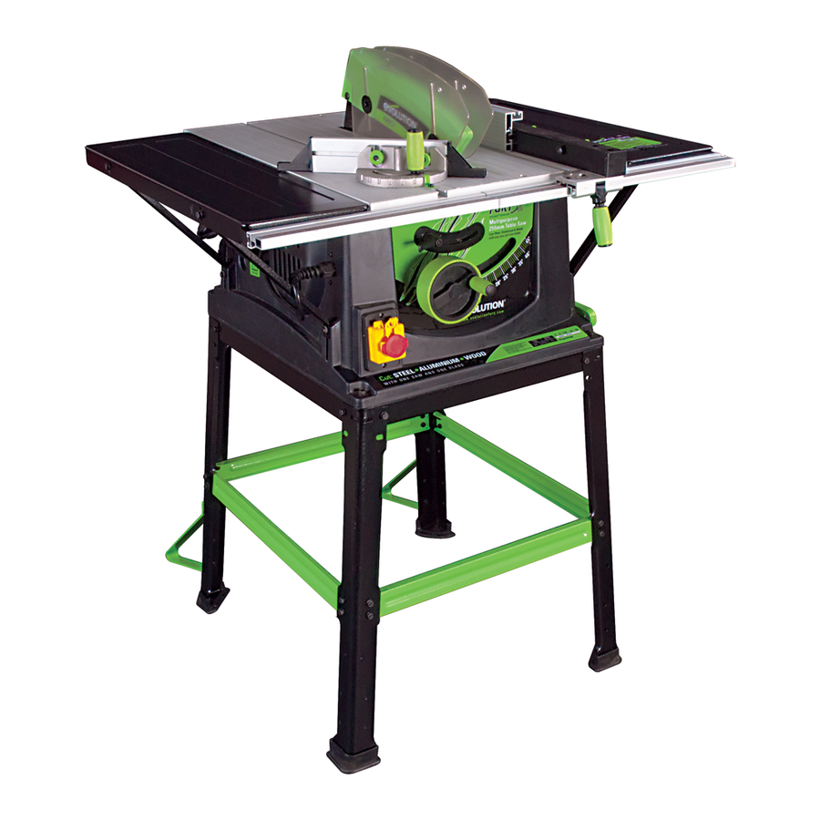
255mm tct multipurpose table saw
Hide thumbs
Also See for FURY5:
- Original instructions manual (36 pages) ,
- Original instructions manual (30 pages)

Related Manuals for Evolution FURY5


Summary of Contents for Evolution FURY5
- Page 1 ® 255mm TCT Multipurpose Table Saw Original Instructions Read instructions before operating this tool. www.evolutionfury.com...
-
Page 2: Table Of Contents
TABLE OF CONTENTS EC - Declaration of Conformity Important Information Instruction Manual 12 Month Limited Warranty Read instructions before operating this tool. General Safety Rules Safety Precautions for Table Saws Symbols Additional Specific Safety Rules Specification Machine Overview Assembly Operation Maintenance Environmental Protection Service Parts Lists... -
Page 3: Ec - Declaration Of Conformity
Sheffield S20 3FR Declare that the product Part numbers: FURY 52551, FURY 52552, FURY 52552EU Evolution: FURY TABLE SAW – 255mm Complies with the essential requirements of the following European Directives: 2006/42/EC – Machine Directive 2006/95/EC – Low Voltage Directive 2004/108/EC –... -
Page 4: 12 Month Limited Warranty
Technical of sale and none shall be binding on Evolution helpline. Power Tools. Questions relating to this limited warranty should be directed to the Helpline. - Page 5 7 - Use the right tool 17 - Avoid unintentional starting - Do not force small tools to do the job of a - Ensure switch is in “off” position when heavy duty tool. plugging in. - Do not use tools for purposes not intended; 18 - Use outdoor extension leads for example do not use circular saws to cut - When the tool is used outdoors, use only...
-
Page 6: Safety Precautions For Table Saws
HEALTH ADVICE SAFETY PRECAUTIONS FOR TABLE SAWS Warning! a) Do not use saw blades which are When drilling, sanding, sawing or grinding, damaged or deformed. dust particles will be produced. In some b) Replace the table insert/access plate if worn. instances, depending on the materials you c) Use only blades as recommended in are working with, this dust can be particularly... -
Page 7: Symbols
Inspect the riving Wear Dust Protection knife regularly and replace it if it is worn. Use Restriction only a genuine Evolution riving knife as this is a of Hazardous dedicated component for this machine. Substances Directive e) Remove adjusting keys and wrenches. -
Page 8: Specification
Maximum depth of cut at 0 73mm o) Use recommended accessories. Only Maximum depth of cut at 45 54mm use genuine Evolution accessories. Net weight 25kg p) Check for damaged parts. Before further Riving Knife Thickness 1.8mm... - Page 9 KNOW YOUR PARTS 1. Fixings grouped in sets 2. Stand components 3. Table extensions and struts etc 4. Other parts – mitre gauge, rip fence, top guard, fence rail www.evolutionfury.com...
-
Page 10: Machine Overview
Machine Overview 8. SLIDING MITRE FENCE 1. ON/OFF SWITCH 9. ANTI-BOUNCE DEVICE 2. BLADE 10. RISE & FALL ADJUSTMENT HANDLE 3. RIVING KNIFE 4. BLADE GUARD 11. BEVEL LOCKING LEVER 12. BEVEL ADJUSTMENT WHEEL 5. RIP FENCE 13. PUSH STICK 6. -
Page 11: Assembly
ASSEMBLY 1. Assembly of the table stand Eight cross-pieces are supplied (Fig 1). The black cross-pieces are for the top of the stand, the green ones are for mid way fixing. The cross-pieces are paired, with two long and two short of each colour. - Page 12 When finally satisfied with the construction, tighten all nuts and bolts securely, and remove the mounting bolts from the corner holes. See Fig 4. 2. Attaching the main body to the stand Warning This machine is heavy, enlist competent help when fastening this machine to its base.
- Page 13 2. Captive nuts are incorporated into the RH and LH edges of the table. Attach the table extensions (single hole to the front) to the table top using the ø5mm socket headed screws and washers. 3. Ensure that the saw table edge and extension table edge are flush and level with each other.
- Page 14 5. The Fence Rail Note The Fence Rail is supplied in two pieces which slot together. The metal locating bar should be inserted into the rectangular voids of the two extrusions to bridge both parts of the fence rail. The bar should be equally located in either side of the fence rail.
- Page 15 6. Checking/Adjusting the Rip Fence When the Fence Rail and Rip Fence have been attached to the machine, the Rip Fence should be checked to ensure that it lies parallel to the blade. 1. Raise the blade to its full height. 2.
- Page 16 Note It is recommended that the anti-bounce device is fitted only when needed (e.g. when cutting thin sheet material or thin walled metal tube etc). At other times store away off the machine for future use. The pillar of the anti-bounce device fits into the socket in the mitre gauge base, and is held in place by a set screw.
-
Page 17: Operation
OPERATION Controls 1. On/Off Safety Switch Warning: Before turning on the switch make sure that the blade guard is correctly installed and operating properly. To start the machine, press the tabs on either side of the red safety button and lift it and the switch cover plate upwards to Fig 18 reveal the on and off buttons. - Page 18 Forwards and backwards adjustment of the rip fence is possible. Loosen the two finger nuts and slide the aluminium extrusion to the desired position. Tighten the finger nuts securely. Note We recommend that normally the rip fence be adjusted so that the rear of the guide is level with the rear of the blade where it emerges from the table.
- Page 19 6. Anti-bounce Device If required, when cutting thin sheet or thin walled box- section material (maximum 3mm thickness applies when Steel cutting), the anti-bounce device can be employed. See Fig 24. Adjust using the adjustable handle and knob for best position. Note Adjust the anti-bounce device so that the head does not quite touch the material to be cut.
-
Page 20: Rip Cutting
4. Compound mitre cutting Compound mitre cutting is a combination of mitre cutting and bevel crosscutting. Adjust the mitre gauge and the blade to the desired angles. Lock both in place. Check that the mitre gauge will pass the saw blade without fouling. -
Page 21: Maintenance
Note Check that the rip fence is locked in position and is parallel to the saw blade. Check that the riving knife is properly aligned with the saw blade. When ripping small section material a push stick should be used to feed/guide the final 300mm of the material past the blade. - Page 22 1. Disconnect the machine from the power supply 2. Remove the blade guard. (see Assembly 7) 3. Remove the table access plate by removing the two countersunk head screws from either end of the access plate. Lift the plate away and carefully store it and its fixing screws for future use.
-
Page 23: Environmental Protection
Note Use only a genuine Evolution Riving Knife, as this is a dedicated component for this machine. Non genuine parts could be dangerous. If in any doubt, please contact the Helpline. Push Stick A plastic push stick is provided with the machine and has its own dedicated storage brackets to the RH side of the machines main body. - Page 24 PARTS LISTS www.evolutionfury.com...
Need help?
Do you have a question about the FURY5 and is the answer not in the manual?
Questions and answers