
Related Manuals for eMachines E732


Summary of Contents for eMachines E732
- Page 1 E732/E732G/E732Z/E732ZG Service Guide Service guide files and updates are available on the ACER/CSD web; for more information, please refer to http://csd.acer.com.tw PRINTED IN TAIWAN...
-
Page 2: Revision History
Revision History Please refer to the table below for the updates made on this service guides. Date Chapter Updates... - Page 3 Copyright Copyright © 2010 by Acer Incorporated. All rights reserved. No part of this publication may be reproduced, transmitted, transcribed, stored in a retrieval system, or translated into any language or computer language, in any form or by any means, electronic, mechanical, magnetic, optical, chemical, manual or otherwise, without the prior written permission of Acer Incorporated.
- Page 4 Conventions The following conventions are used in this manual: Denotes actual messages that appear SCREEN MESSAGES on screen. NOTE Gives bits and pieces of additional information related to the current topic. WARNING Alerts you to any damage that might result from doing or not doing specific actions.
- Page 5 Preface Before using this information and the product it supports, please read the following general information. This Service Guide provides you with all technical information relating to the BASIC CONFIGURATION decided for Acer's "global" product offering. To better fit local market requirements and enhance product competitiveness, your regional office MAY have decided to extend the functionality of a machine (e.g.
-
Page 7: Table Of Contents
Table of Contents System Specifications Features ............1 System Block Diagram . - Page 8 Table of Contents Removing the CPU ..........68 Removing the Mainboard .
- Page 9 E732 series FRU List ........144...
- Page 10 Table of Contents...
-
Page 11: System Specifications
Chapter 1 System Specifications Features Below is a brief summary of the computer’s many features: NOTE: Items denoted with an (*) are only available for selected models. Operating system • Genuine Windows® 7 Home Premium 64-bit • Genuine Windows® 7 Home Basic 64-bit CPU and chipset •... -
Page 12: Optical Media Drive
Graphics • Dual independent display support • 16.7 million colors • External resolution / refresh rates: • VGA port up to 2560 x 1600: 60 Hz • HDMI™ port up to 1920 x 1080: 60 Hz • MPEG-2/DVD decoding eME732/eME732Z •... -
Page 13: Wireless And Networking
• Battery life: 4.5 hours • ENERGY STAR® Input and control • Keyboard • 86-/87-/91-key eMachines FineTip keyboard with international language support • Touchpad • Multi-gesture Touchpad, supporting two-finger scroll, pinch, rotate, flip • Media keys • Media control keys (printed on keyboard): play/pause, stop, previous, next, volume up, volume... -
Page 14: Options And Accessories
1/2/4 GB DDR3 1066 MHz soDIMM module • 3-pin 65 W AC adapter • 48Wh 4400 mAh 6-cell Li-ion battery pack Software • Productivity • eMachines Power Management • eMachines Recovery Management • Adobe® Flash® Player 10 • Adobe® Reader® 9.1 • Google Toolbar™... -
Page 15: System Block Diagram
System Block Diagram Chapter 1... -
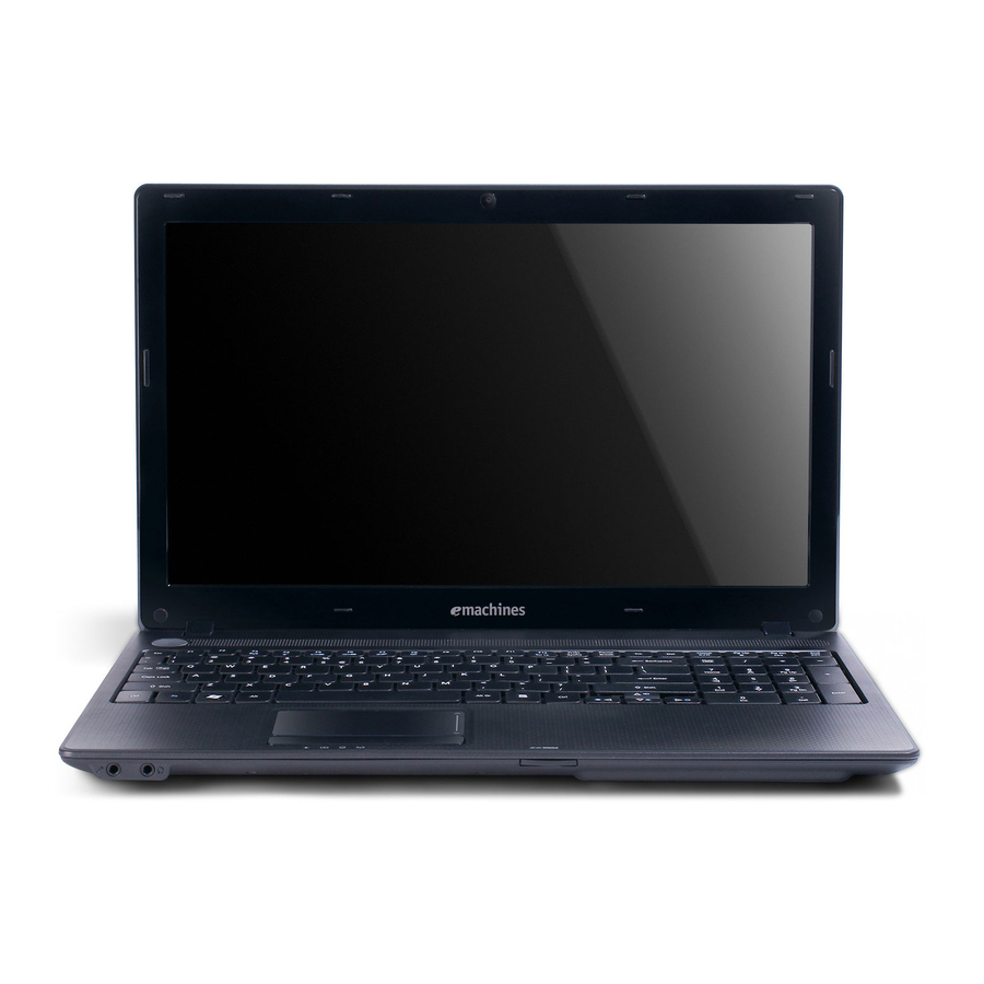
Page 16: Your Acer Notebook Tour
Your Acer Notebook tour Top View Icon Item Description Integrated Web camera for video communication (only for certain webcam models). Display screen Also called Liquid-Crystal Display (LCD), displays computer output (configuration may vary by model). Power button Turns the computer on and off. Keyboard For entering data into your computer Touchpad... -
Page 17: Closed Front View
Icon Item Description Power indicator Indicates the computer's power status. Battery indicator Indicates the computer's battery status. 1. Charging: The light shows amber when the battery is charging. 2. Fully charged: The light shows blue when in AC mode. HDD indicator Indicates when the hard disk drive is active. -
Page 18: Right View
Right View Icon Item Description USB 2.0 ports Connect to USB 2.0 devices (e.g., USB mouse, USB camera). Optical drive Internal optical drive; accepts CDs or DVDs. Optical disk access Lights up when the optical drive is indicator active. Optical drive eject Ejects the optical disk from the drive. -
Page 19: Base View
Base View Icon Item Description Battery bay Houses the computer's battery pack. Battery lock Locks the battery in position. Ventilation slots Enable the computer to stay cool, even after prolonged use. Battery release Releases the battery for removal. latch Indicators The computer has several easy-to-read status indicators. -
Page 20: Touchpad Basics
Touchpad Basics The following items show you how to use the touchpad: • Move your finger across the touchpad (1) to move the cursor. • Press the left (2) and right (3) buttons located beneath the touchpad to perform selection and execution functions. -
Page 21: Using The Keyboard
Using the Keyboard The keyboard has full-sized keys and an embedded numeric keypad, separate cursor, lock, Windows, function and special keys. Lock Keys and embedded numeric keypad The keyboard has two lock keys which you can toggle on and off. Lock key Description Caps Lock... -
Page 22: Windows Keys
Windows Keys The keyboard has two keys that perform Windows-specific functions. Description Windows key Pressed alone, this key has the same effect as clicking on the Windows Start button; it launches the Start menu. It can also be used with other keys to provide a variety of functions: : Open or close the Start menu <... -
Page 23: Hot Keys
Hot Keys The computer employs hotkeys or key combinations to access most of the computer’s controls like screen brightness, volume output and the BIOS utility. To activate hot keys, press and hold the <Fn> key before pressing the other key in the hotkey combination. Hotkey Icon Function... -
Page 24: Hardware Specifications And Configurations
Hardware Specifications and Configurations Processor Item Specification CPU Type Intel Arrandale CPU Package rPGA 989 Core Logic Intel Ibex-Peak (HM55) Core Voltage 0.725–1.4 Processor Specifications Mfg. Cache Core Item Cores Speed Speed Tech Size Voltage (GHz) Ci3350M 2.26 G 2.5 GT/s PGA988 0.725–... - Page 25 System Memory Item Specification Memory controller Intel Arrandale Memory size 0MB (no on-board memory) DIMM socket number 2 sockets Supports memory size per socket 4 GB Supports maximum memory size 8 GB Supports DIMM type DDR 3 Synchronous DRAM Supports DIMM speed 1600Mbps/1333Mbps/1066Mbps Supports DIMM voltage 1.5V +/- 0.075V...
- Page 26 Memory Combinations Slot 1 Slot 2 Total Memory 512MB 512MB 1024MB 1024MB 2048MB 2048MB 4096MB 4096MB 512MB 512MB 1024MB 512MB 1024MB 1536MB 512MB 2048MB 2560MB 512MB 4096MB 4608MB 1024MB 512MB 1536MB 1024MB 1024MB 2048MB 1024MB 2048MB 3072MB 1024MB 4096MB 5120MB 2048MB 512MB 2560MB...
- Page 27 Bluetooth Interface Item Specification Chipset BT 2.1 • Foxconn Bluetooth BRM2070 • Foxconn Bluetooth AR3011 BT 3.0 • Foxconn Bluetooth BRM2046 • Foxconn Bluetooth ATH AR3011 • Foxconn Bluetooth BRM 2070 Radio Technology FHSS Operating Frequency 2402 ~ 2480MHz ISM band Channel Numbers 79 channels with 1MHz BW Transmitter Output Power...
- Page 28 Item Specification Disks Spindle 5400 speed (RPM) Performance Specifications Buffer size 8 MB Interface SATA Max. Media Transfer Rate (Mbytes/sec max.) Max. Data 1175 108544 1175 1031 108544 Transfer Rate (Mbytes/sec) DC Power Requirements Voltage 5V ±5% tolerance Hard Disk Drive Interface (continued) Item Specification Capacity (GB)
- Page 29 Hard Disk Drive Interface (continued) Item Specification Capacity (GB) Vendor & Model Name Toshiba MK6465GSX Western Digital Western Digital WD7500BPVT-22HXZT1 WD6400BEVT-22A0RT0 Bytes per sector Data heads Drive Format Disks Spindle speed (RPM) 5400 Performance Specifications Buffer size 8 MB Interface SATA Max.
- Page 30 Video Interface Item Specification Chipset Arrandale Robson XT & Park XT Capilano-Pro & Madison-Pro Package rPGA 989 962 FCBGA Interface LVDS / CRT Compatibility 1366x768/60Hz(16:9) / 1280x720/60Hz(16:9) / 1024x768/60Hz(4:3) / 800x600/60Hz(4:3) Sampling rate 60Hz Internal microphone Internal speaker / quantity VRAM Item Specification...
- Page 31 Super-Multi Drive Module Item Specification Vendor & model HLDS GT32N Panasonic UJ8A0 name Performance With CD Diskette With DVD With CD Diskette With DVD Diskette Specification Diskette max. 24x CAV max. 8X CAV Transfer rate (MB/ Sustained: Sustained: sec) (max. 3.6 MB/s) (max.
- Page 32 Super-Multi Drive Module (continued) Item Specification Vendor & model PLDS DS-8A5SH Sony AD7585H name Performance With CD Diskette With DVD With CD Diskette With DVD Diskette Specification Diskette Transfer rate (MB/ Sustained: Sustained: Sustained: Sustained: sec) - CD-ROM inside - DVD-ROM - CD-ROM inside - DVD-ROM inside inside 3.7 MB/s...
- Page 33 Super-Multi Drive Module (continued) Item Specification Vendor & model name Toshiba TS-L633F Performance Specification With CD Diskette With DVD Diskette Transfer rate (MB/sec) Sustained: Sustained: - CD-ROM/R Read (Mode1) Max - DVD-Single Read Max 10.8 3.6 MB/sec MB/sec - CD-RW Read (Mode1) Max 3.6 - DVD-ROM Dual Read Max MB/sec 10.8 MB/sec...
- Page 34 I/O Ports Item Specification I/O support • 2-in-1 card reader (SD™, MMC) • Three USB 2.0 ports • HDMI™ port with HDCP support • External display (VGA) port • Headphone/speaker/line-out jack • Microphone-in jack • Ethernet (RJ-45) port • DC-in jack for AC adapter Main Battery Specification Item...
- Page 35 External Display Supported Resolution Resolution 24 bits 30 bits 36 bits 48 bits 640X480p/60Hz 4:3 720X480p/60Hz 4:3 640X480p/60Hz 16:9 1280X720p/60Hz 16:9 1920X1080p/60Hz 16:9 1440X480p/60Hz 4:3 1440X480p/60Hz 16:9 1920X1080p/50Hz 16:9 720X576p/50Hz 4:3 720X576p/50Hz 16:9 1280X720p/50Hz 16:9 1920X1080i/50Hz 16:9 1440X576i/50Hz 4:3 1440X576i/50Hz 16:9 1920X1080p/50Hz 16:9 Item Specification...
- Page 36 Camera Item Specification Vendor and model Chicony Liteon Liteon Suyin CH9665SN LT9665AL LT6AASP SY9665SN Type CMOS image sensor with SXGA Interface USB 2.0 Focusing range 26.6cm ~ infinity 32cm ~ infinity 31.5 cm~infinity 70 mm Dimensions 65.0±0.3 x 65.0 x 8.0 x 3.53 65 x 8 x 3.69 65 x 8.0 x 3.74 8.0±0.1 x...
- Page 37 System Power Management Item Initial Standby Suspend Hibernate Soft Off Initial On(S0) Standby(S1) Suspend(S3) Hibernate(S4) Soft Off(S5) Mechanical off is a condition where all power except the RTC battery has been removed from the system. 1. Initial to On state: When the AC adapter or Battery pack has been plugged into the system, the I WPC781 will be reset and initial all output pins then the system goes into Initial state and waiting for power on event.
- Page 38 Chapter 1...
-
Page 39: System Utilities
Chapter 2 System Utilities BIOS Setup Utility The BIOS Setup Utility is a hardware configuration program built into your computer’s BIOS (Basic Input/ Output System). Your computer is already properly configured and optimized, and you do not need to run this utility. However, if you encounter configuration problems, you may need to run Setup. -
Page 40: Information
Information The Information screen displays a summary of your computer hardware information. NOTE: The system information is subject to different models. Parameter Description CPU Type This field shows the CPU type and speed of the system. CPU Speed This field shows the speed of the CPU. IDE0 Model Name This field shows the model name of HDD installed in the system. -
Page 41: Main
Main The Main screen allows the user to set the system time and date as well as enable and disable boot option and recovery. NOTE: The screen above is for your reference only. Actual values may differ. The table below describes the parameters in this screen. Settings in boldface are the default and suggested parameter settings. -
Page 42: Security
Security The Security screen contains parameters that help safeguard and protect your computer from unauthorized use. The table below describes the parameters in this screen. Settings in boldface are the default and suggested parameter settings. Parameter Description Option Supervisor Password Is Shows the setting of the Supervisor password Clear or Set User Password Is... -
Page 43: Setting A Password
Setting a Password Follow these steps as you set the user or the supervisor password: Use the and keys to highlight the Set Supervisor Password parameter and press the Enter key. The Set Supervisor Password box appears: Type a password in the “Enter New Password” field. The password length can not exceeds 8 alphanumeric characters (A-Z, a-z, 0-9, not case sensitive). -
Page 44: Changing A Password
Changing a Password Use the and keys to highlight the Set Supervisor Password parameter and press the Enter key. The Set Supervisor Password box appears. Type the current password in the Enter Current Password field and press Enter. Type a password in the Enter New Password field. Retype the password in the Confirm New Password field. -
Page 45: Boot
Boot This menu allows the user to decide the order of boot devices to load the operating system. Bootable devices includes the USB diskette drives, the onboard hard disk drive and the DVD drive in the module bay. Chapter 2... -
Page 46: Exit
Exit The Exit screen allows you to save or discard any changes you made and quit the BIOS Utility. The table below describes the parameters in this screen. Parameter Description Exit Saving Changes Exit System Setup and save your changes to CMOS. Exit Discarding Exit utility without saving setup data to CMOS. -
Page 47: Bios Flash Utility
BIOS Flash Utility The BIOS flash memory update is required for the following conditions: New versions of system programs • New features or options • Restore a BIOS when it becomes corrupted. • DOS Flash Utility Perform the following steps to use the DOS Flash Utility: Create a DOS bootable USB HDD. -
Page 48: Winflash Utility
WinFlash Utility Perform the following steps to use the WinFlash Utility: Double click the WinFlash executable (ZQ8_100W.exe) Click OK to begin the update. A progress screen will display the current state of BIOS flash process. When the process has completed, close all applications and reboot the system. Chapter 2... -
Page 49: Remove Hdd/Bios Password Utilities
Remove HDD/BIOS Password Utilities This section provides you with details about removing HDD/BIOS password: Remove HDD Password: If you key in the wrong HDD password three times, an error is generated. To reset the HDD password, perform the following steps: After the error is displayed, press Enter to proceed to the next screen. -
Page 50: Removing Bios Passwords
Removing BIOS Passwords: If you key in the wrong Supervisor Password three times, the message System will halt! is displayed on the screen. If the user is unable to obtain the correct password then it must be removed. There are two methods to do this. Method 1: If the BIOS menu item “Power on Password”... -
Page 51: Miscellaneous Utilities
Miscellaneous Utilities Using DMITools The DMI (Desktop Management Interface) Tool copies BIOS information to eeprom to be used in the DMI pool for hardware management. When the BIOS displays Verifying DMI pool data, it is checking the table correlates with the hardware before sending the information to the operating system (Windows, etc.). - Page 52 Chapter 2...
-
Page 53: Machine Disassembly And Replacement
Chapter 3 Machine Disassembly and Replacement IMPORTANT:The outside housing and color may vary from the mass produced model. This chapter contains step-by-step procedures on how to disassemble the notebook computer for maintenance and troubleshooting. Disassembly Requirements To disassemble the computer, you need the following tools: •... -
Page 54: Pre-Disassembly Instructions
Pre-disassembly Instructions Before proceeding with the disassembly procedure, make sure that you do the following: 1. Turn off the power to the system and all peripherals. 2. Unplug the AC adapter and all power and signal cables from the system. 3. -
Page 55: Disassembly Process
Disassembly Process The disassembly process is divided into the following stages: • External module disassembly • Main unit disassembly • LCD module disassembly The flowcharts provided in the succeeding disassembly sections illustrate the entire disassembly sequence. Observe the order of the sequence to avoid damage to any of the hardware components. For example, if you want to remove the mainboard, you must first remove the keyboard, then disassemble the inside assembly frame in that order. -
Page 56: External Modules Disassembly Process
External Modules Disassembly Process IMPORTANT:The outside housing and color may vary from the mass produced model. External Modules Disassembly Flowchart The flowchart below gives you a graphic representation on the entire disassembly sequence and instructs you on the components that need to be removed during servicing. For example, if you want to remove the mainboard, you must first remove the keyboard, then disassemble the inside assembly frame in that order. -
Page 57: Removing The Battery Pack
Removing the Battery Pack 1. Turn the computer over. Slide the battery lock in the direction shown. 2. Slide and hold the battery release latch to the release position (1), then lift out the battery pack from the main unit (2). NOTE: The battery has been highlighted with a yellow oval as shown in the above image. -
Page 58: Removing The Sd Dummy Card
Removing the SD Dummy Card 1. See “Removing the Battery Pack” on page 47. 2. Push the SD dummy card all the way in to eject it. 3. Pull it out from the slot. Chapter 3... -
Page 59: Removing The Keyboard
Removing the Keyboard NOTE: NOTE: The model displayed in this service guide may differ in color to the one in your package. 1. See “Removing the Battery Pack” on page 47. 2. Turn the computer over and fully open the lid. There are five (5) securing clips that must be released in order to remove the keyboard. - Page 60 5. Unlock the keyboard FPC and disconnect the cable as shown. Lift the keyboard clear of the chassis. 6. Unlock and disconnect the touchpad FPC from the mainboard: Chapter 3...
-
Page 61: Removing The Odd Module
Removing the ODD Module 1. See “Removing the Battery Pack” on page 47. 2. Remove the one (1) screw securing the ODD module in place. Step Size Quantity Screw Type ODD Bracket M2.5*6.0-I Disassembly 3. Grasp the ODD by the bezel and slide it out of the chassis. Chapter 3... - Page 62 4. Remove the ODD bezel by rotating the top edge downward. 5. Remove the two screws securing the ODD bracket. Step Size Quantity Screw Type ODD Bracket M2.0*3.0-I Disassembly 6. Remove the bracket from the ODD. Chapter 3...
-
Page 63: Main Unit Disassembly Process
Main Unit Disassembly Process Main Unit Disassembly Flowchart NOTE: Use the process highlighted in red to access the Bluetooth module Chapter 3... -
Page 64: Removing The Lower Cover
Screw List Step Screw Quantity Part No. Lower Cover M2.5*6.0-I 86.A08V7.004 Battery Bay M2.0*3.0-I 86.ARE07.002 WLAN Module Disassembly M2.0*3.0-I 86.ARE07.002 USB Module Disassembly M2.0*4.0-I.0 86.ARE07.002 HDD Carrier Disassembly M3*0.5+3.5I 86.N1407.007 LCD Module Disassembly M2.5*6.0-I 86.A08V7.004 Thermal Module Disassembly M2.0*4.0-I.0 86.R6Z07.002 Mainboard Disassembly M2.0*4.0-I.0 86.R6Z07.002... - Page 65 3. Grasp the ODD bay with the right hand and the right edge of the lower cover with the right hand. Lift the lower cover from the device. Chapter 3...
-
Page 66: Disassembly Overview
Disassembly Overview 1. See “Removing the Lower Cover” on page 56. 2. This section is an overview of the major components of the main unit. Item Description Item Description VGA heatsink Speaker cable LVDS cable Bluetooth cable Thermal module RTC battery WLAN module DIMM module(s) USB module... -
Page 67: Removing The Dimm Modules
Removing the DIMM Modules 1. See “Removing the Lower Cover” on page 54. 2. Push out the release latches on both sides of the DIMM socket to release the DIMM module. 3. Remove the DIMM module. 4. Repeat steps for the second DIMM module if present. Chapter 3... -
Page 68: Removing The Wlan Module
Removing the WLAN Module 1. See “Disassembly Overview” on page 58. 2. Disconnect the two (2) cables from the WLAN module. 3. Remove the one (1) screw. Step Size Quantity Screw Type WLAN Module M2.0*3.0-I Disassembly Chapter 3... -
Page 69: Removing The Usb Board
4. Detach and remove the WLAN module from the WLAN socket. Removing the USB Board 1. See “Disassembly Overview” on page 58. 2. Unlock and disconnect the USB FFC from the USB board. Repeat for the mainboard connector. Chapter 3... - Page 70 3. Remove the one (1) screw from the USB board. Step Size Quantity Screw Type USB Board M2.0*4.0-I Disassembly 4. Lift the USB board upward and away from the chassis. Chapter 3...
-
Page 71: Removing The Rtc Battery
Removing the RTC Battery 1. See “Disassembly Overview” on page 58. 2. Disconnect the RTC battery cable from the mainboard. 3. Lift the RTC battery away from the mainboard. NOTE: The RTC battery has been highlighted with a yellow callout in the previous image. Please detach the RTC battery and follow local regulations for disposal. -
Page 72: Removing The Hdd Module
Removing the HDD Module 1. See “Disassembly Overview” on page 58. 2. Using the pull-tab, slide the HDD module in the direction of the arrow to disconnect the interface. 3. Remove the HDD from the bay. Chapter 3... - Page 73 4. Remove the two (2) screws from the bracket. Step Size Quantity Screw Type HDD Carrier M3*0.5+3.5I Disassembly 5. Remove the bracket from the HDD. Chapter 3...
-
Page 74: Removing The Lcd Module
Removing the LCD Module 1. See “Disassembly Overview” on page 58. 2. Remove the tape adhering the antenna cables to the mainboard. 3. Remove the WLAN antennas from the cable guides. 4. Unlock and disconnect the LVDS cable. Chapter 3... - Page 75 5. Remove the two (2) screws from the left and right hinges. Step Size Quantity Screw Type LCD Module M2.5*6.0-I Disassembly 6. Tilt the upper cover upwards (1) and push down near the hinges to separate it from the LCD module (2). 7.
-
Page 76: Removing The Thermal Module
Removing the Thermal Module 1. See “Disassembly Overview” on page 58. 2. Loosen the two (2) captive screws connecting the VGA heat sink to the mainboard. 3. Lift the VGA heat sink using the thumb and forefinger to remove it from the mainboard. 4. - Page 77 5. Loosen the six (6) captive screws (in numerical order from 1 to 6) and remove the one (1) screw from the fan module. Step Size Quantity Screw Type Thermal Module M2.0*4.0-I (green Disassembly callout) 6. Carefully lift up the thermal module assembly and remove it from the mainboard. IMPORTANT:Place the thermal module on a clean, dry surface when it is not installed.
-
Page 78: Removing The Cpu
Removing the CPU 1. See “Removing the Thermal Module” on page 68. 2. Using a slotted screw driver, rotate the CPU locking screw 180° counter-clockwise as shown. 3. Carefully lift the CPU clear of the socket. IMPORTANT:Place the CPU on a clean, dry surface when it is not installed. Chapter 3... -
Page 79: Removing The Mainboard
Removing the Mainboard 1. See “Removing the CPU” on page 70. 2. Disconnect the speaker cable from the mainboard connector and move it away from the mainboard. 3. Disconnect the Bluetooth cable from the mainboard connector and move it away from the mainboard. Chapter 3... - Page 80 4. Remove the one (1) securing screw from the mainboard (1) and lift the mainboard away from the lower cover (2). Step Size Quantity Screw Type Mainboard M2.0*4.0-I Disassembly Chapter 3...
-
Page 81: Removing The Bluetooth Module
Removing the Bluetooth Module 1. See “Removing the Mainboard” on page 71. 2. Turn the mainboard over and locate the Bluetooth module. 3. Separate the Bluetooth cable from the adhesive strip on the mainboard. Chapter 3... - Page 82 4. Disconnect the Bluetooth cable from the Bluetooth module. 5. Remove the one (1) screw securing the Bluetooth module to the mainboard. Step Size Quantity Screw Type Bluetooth Module M2.0*3.0-I Disassembly 6. Pull the Bluetooth module away from the metal post (1) and then lift up to remove it from the mainboard (2). Chapter 3...
- Page 83 NOTE: Circuit boards >10 cm² have been highlighted with a yellow rectangle as shown in the previous image. Please detach the Circuit board and follow local regulations for disposal. Chapter 3...
-
Page 84: Lcd Module Disassembly Process
LCD Module Disassembly Process LCD Module Disassembly Flowchart Screw List Step Screw Quantity Part No. LCD Bezel Disassembly M2.5*4.0-I 86.T23V7.009 LCD Panel Disassembly M2.0*4.0-I 86.R6Z07.002 LCD Hinge Disassembly M2.0*3.0-I 86.ARE07.002 Chapter 3... -
Page 85: Removing The Lcd Bezel
Removing the LCD Bezel 1. See “Removing the LCD Module” on page 66. 2. Remove the two (2) bezel screws from the LCD modulele. Step Size Quantity Screw Type LCD Bezel M2.5*4.0-I Disassembly 3. Pry the bezel upwards at the base of the LCD module releasing it from the latches. Chapter 3... - Page 86 4. Continue separating the latches along the sides of the bezel working towards the top. 5. Release the latches at the top of the LCD bezel. 6. Lift the Bezel clear of the LCD module. Chapter 3...
-
Page 87: Removing The Camera (Ccd) Module
Removing the Camera (CCD) Module 1. See “Removing the LCD Bezel” on page 77. 2. Locate the CCD module on the LCD cover. 3. Lift the CCD module from the LCD cover. 4. Disconnect the cable as shown. NOTE: Take care not to damage the cable. Chapter 3... -
Page 88: Removing The Lcd Panel
Removing the LCD Panel 1. See “Removing the LCD Bezel” on page 77. 2. Remove the six (6) securing screws from the LCD panel. Step Size Quantity Screw Type LCD Panel M2.0*4.0-I Disassembly 3. Remove the LVDS cable from the cable guides. Chapter 3... -
Page 89: Remove The Lcd Hinges
4. Lift the LCD panel clear of the LCD cover as shown. Remove the LCD Hinges 1. See “Removing the LCD Panel” on page 80. 2. Remove the four (4) screws, 2 on each side. Separate the hinges from the LCD panel. Step Size Quantity... -
Page 90: Removing The Lvds Cable
Removing the LVDS Cable 1. See “Removing the LCD Panel” on page 80. 2. Locate the LVDS cable on the LCD panel. 3. Detach the CCD cable from the back of the LCD panel. Chapter 3... - Page 91 4. Detach the LVDS cable from the adhesive strip on the LCD panel. 5. Remove the yellow tape securing the LVDS cable. 6. Starting from the top, remove the clear mylar covering and disconnect the LVDS cable from the LCD panel. Chapter 3...
-
Page 92: Removing The Wlan Antennas
Removing the WLAN Antennas 1. See “Removing the LCD Panel” on page 80. 2. Remove the black and white WLAN antennas from the cable guides. 3. Remove the black antenna from the LCD cover. Repeat for the white antenna. Chapter 3... -
Page 93: Lcd Module Assembly Process
LCD Module Assembly Process Replacing the WLAN Antennas 1. Place the black antenna onto the LCD cover as shown. Repeat for the white antenna. 2. Place the black and white WLAN antennas into the cable guides as shown. Chapter 3... -
Page 94: Replacing The Lvds Cable
Replacing the LVDS Cable 1. Turn the LCD panel face down on a non-abrasive, clean surface. Ensure the panel face does not get damaged. Connect the LVDS cable to the LCD panel. Place the clear mylar tape over the connector and press firmly. 2. - Page 95 4. Adhere the camera cable to the LCD panel. NOTE: Ensure that the cable is aligned correctly on the panel to prevent damage to the CCD module. Marked area is provided to show correct position of LVDS cable. Chapter 3...
-
Page 96: Replacing The Lcd Hinges
Replacing the LCD Hinges 1. See “Removing the LCD Panel” on page 80. 2. Replace the four (4) screws, 2 on each side to secure the hinges. Step Size Quantity Screw Type LCD Hinge M2.0*3.0-I Assembly Chapter 3... -
Page 97: Replacing The Lcd Panel
Replacing the LCD Panel 1. Place the LCD panel on the LCD cover as shown. 2. Place the LVDS cable into the cable guides. Chapter 3... - Page 98 3. Replace the six (6) securing screws to secure the LCD panel. Step Size Quantity Screw Type LCD Panel M2.0*4.0-I Assembly Chapter 3...
-
Page 99: Replacing The Camera (Ccd) Module
Replacing the Camera (CCD) Module 1. Connect the CCD cable as shown. NOTE: Take care not to damage the cable. 2. Place the camera module onto the LCD cover. Apply gentle pressure to fix the adhesive. Chapter 3... -
Page 100: Replacing The Lcd Bezel
Replacing the LCD Bezel 1. Place the bezel hinge covers over the hinges. 2. Ensure the LVDS and WLAN antenna cable bundle are exiting the left hinge as shown. 3. Apply pressure to snap the latches together. Chapter 3... - Page 101 4. Apply pressure along the bottom of the bezel to attach the latches. 5. Apply pressure along the sides of the bezel to attach the latches. 6. Apply pressure along the top of the bezel to attach the latches. Chapter 3...
- Page 102 7. Replace the two (2) bezel screws. Step Size Quantity Screw Type LCD Bezel M2.5*4.0 Assembly Chapter 3...
-
Page 103: Main Unit Assembly Process
Main Unit Assembly Process Replacing the Bluetooth Module 1. Lower the Bluetooth module onto the mainboard (1) and then push it against the metal post until firmly attached (2). 2. Replace the one (1) screw to secure the Bluetooth module to the mainboard. Step Size Quantity... - Page 104 3. Connect the Bluetooth cable to the Bluetooth module. 4. Adhere the Bluetooth cable to the mainboard. Chapter 3...
-
Page 105: Replacing The Mainboard
Replacing the Mainboard 1. Place the mainboard onto the upper cover and secure the one (1) screw. Step Size Quantity Screw Type Mainboard M2.0*4.0 Assembly Chapter 3... - Page 106 2. Connect the Bluetooth cable to the mainboard. 3. Connect the speaker cable to the mainboard. Chapter 3...
-
Page 107: Replacing The Cpu
Replacing the CPU IMPORTANT:The CPU has a Pin1 locator (1) that must be positioned corresponding to the marker (2) on the CPU socket. 1. Place the CPU into the CPU socket as shown, taking note of the Pin1 locator. 2. Using a slotted screw driver, rotate the CPU locking screw 180° clockwise as shown to secure it in the package. -
Page 108: Replacing The Thermal Module
Replacing the Thermal Module IMPORTANT:Apply a suitable thermal grease and ensure all heat pads are in place before replacing the thermal module The following thermal grease types are approved for use: • Silmore GP50 • Honeywell PCM45F-SP • ShinEtsu 7762 The following thermal pads are approved for use: •... - Page 109 4. Tighten the four (4) captive screws (in numerical order from 1 to 4) and replace the one (1) screw to secure the CPU thermal module. Step Size Quantity Screw Type Thermal Module M2.0*4.0-I (green Assembly callout) 5. Connect the fan cable as shown. Chapter 3...
- Page 110 6. Place the VGA heat sink on the mainboard using the thumb and forefinger as shown. 7. Tighten the two (2) captive screws to secure the VGA heat sink to the mainboard. Chapter 3...
-
Page 111: Replacing The Lcd Module
Replacing the LCD Module 1. Place the upper cover onto the LCD module and lower into place. Lower the hinges so they are flush with the hinge plates on the upper cover. 2. Replace the two (2) screws to secure the left and right hinges. Step Size Quantity... - Page 112 3. Connect and lock the LVDS cable. 4. Place the WLAN antenna bundle into the cable guides around the fan module. 5. Place the adhesive ground wire attached to the WLAN antenna cable bundle onto the mainboard. Chapter 3...
-
Page 113: Replacing The Hdd Module
Replacing the HDD Module 1. Place the carrier onto the HDD. 2. Replace the two (2) screws to secure the HDD carrier. Step Size Quantity Screw Type HDD Carrier M3*0.5+3.5I Assembly 3. Place HDD on the lower cover. Chapter 3... - Page 114 4. Using the pull-tab, slide the HDD module in the direction of the arrow to connect the interface. Chapter 3...
-
Page 115: Replacing The Rtc Battery
Replacing the RTC Battery 1. Place the RTC battery onto the mainboard. 2. Connect the RTC battery cable to the mainboard connector. Chapter 3... -
Page 116: Replacing The Usb Board
Replacing the USB Board 1. Place the USB board onto the upper cover. 2. Replace one (1) screw to secure the USB board. Step Size Quantity Screw Type USB Board M2.0*4.0 Assembly Chapter 3... -
Page 117: Replacing The Wlan Module
3. Connect and lock the USB FFC to the USB board. Repeat for the mainboard connector. Replacing the WLAN Module 1. Insert the WLAN module into the WLAN socket. Chapter 3... - Page 118 2. Replace the one (1) screw. Step Size Quantity Screw Type WLAN Board M2.0*3.0-I Assembly 3. Connect the two (2) antenna cables to the WLAN module as shown. NOTE: Cable placement is as follows: black (Main) to connector J1, white (AUX) to connector J2. Chapter 3...
-
Page 119: Replacing The Dimm Modules
Replacing the DIMM Modules 1. Insert the DIMM module into the DIMM connector. 2. Press down to lock the DIMM module in place. 3. Repeat steps 1 and 2 for the second DIMM module if present. Chapter 3... -
Page 120: Replacing The Lower Cover
Replacing the Lower Cover 1. Place the lower cover onto the device. 2. Replace the twenty three (23) screws to secure the lower cover to the device. Step Size Quantity Screw Type Lower Cover M2.5*6.0-I (red callout) Battery Bay M2.0*3.0-I (green callout) Chapter 3... -
Page 121: External Module Assembly Process
External Module Assembly Process Replacing the ODD Module 1. Place the ODD bracket onto the ODD module and replace the two (2) screws to secure it. Step Size Quantity Screw Type ODD Bracket M2.0*3.0-I Assembly 2. Press the bezel into the tray, bottom edge first, to secure it to the ODD module. Chapter 3... - Page 122 3. Push the ODD module into the ODD bay until it is flush with the casing. 4. Replace the one (1) screw to secure the module. Step Size Quantity Screw Type ODD Module M2.5*6.0-I Assembly Chapter 3...
-
Page 123: Replacing The Keyboard
Replacing the Keyboard 1. Connect and lock the touchpad FFC to the mainboard connector. 2. Place the keyboard face down on the upper cover. Connect the keyboard FPC to the mainboard and secure the locking latch. 3. Turn the keyboard over and slide the front edge into the upper cover, ensuring that the four locating tabs are correctly seated. - Page 124 4. Press down as indicated to secure the keyboard in place. Chapter 3...
-
Page 125: Replacing The Sd Dummy Card
Replacing the SD dummy card 1. Insert the SD dummy card into the slot and push until the card clicks into place and is flush with the casing. Replacing the Battery Pack 1. Insert the battery pack and press down. 2. - Page 126 Chapter 3...
-
Page 127: Troubleshooting
Common Problems Use the following procedure as a guide for computer problems. NOTE: The diagnostic tests are intended to test only eMachines products. Non-eMachines products, prototype cards, or modified options can give false errors and invalid system responses. Obtain the failing symptoms in as much detail as possible. -
Page 128: Power On Issue
Power On Issue If the system doesn’t power on, perform the following actions one at a time to correct the problem. Do not replace a non-defective FRUs: Computer Shutsdown Intermittently If the system powers off at intervals, perform the following actions one at a time to correct the problem. Check the power cable is properly connected to the computer and the electrical outlet. -
Page 129: No Display Issue
No Display Issue If the Display doesn’t work, perform the following actions one at a time to correct the problem. Do not replace a non-defective FRUs: No POST or Video If the POST or video doesn’t display, perform the following actions one at a time to correct the problem. Make sure that the internal display is selected. -
Page 130: Random Loss Of Bios Settings
Abnormal Video Display If video displays abnormally, perform the following actions one at a time to correct the problem. Reboot the computer. If permanent vertical/horizontal lines or dark spots display in the same location, the LCD is faulty and should be replaced. See “Disassembly Process” on page 47. If extensive pixel damage is present (different colored spots in the same locations on the screen), the LCD is faulty and should be replaced. -
Page 131: Lcd Failure
LCD Failure If the LCD fails, perform the following actions one at a time to correct the problem. Do not replace a non- defective FRUs: Built-In Keyboard Failure If the built-in Keyboard fails, perform the following actions one at a time to correct the problem. Do not replace a non-defective FRUs: Chapter 4... -
Page 132: Touchpad Failure
Touchpad Failure If the Touchpad doesn’t work, perform the following actions one at a time to correct the problem. Do not replace a non-defective FRU: Internal Speaker Failure If the internal Speakers fail, perform the following actions one at a time to correct the problem. Do not replace a non-defective FRU: Chapter 4... -
Page 133: Internal Microphone Failure
Internal Microphone Failure If the internal Microphone fails, perform the following actions one at a time to correct the problem. Do not replace a non-defective FRU: USB Failure If the internal USB module fails, perform the following actions one at a time to correct the problem. Do not replace a non-defective FRU: Chapter 4... -
Page 134: Sound Problems
Sound Problems If sound problems are experienced, perform the following actions one at a time to correct the problem. Reboot the computer. Navigate to Start Control Panel System and Maintenance System Device Manager. Check the Device Manager to determine that: •... -
Page 135: Hdd Not Operating Correctly
HDD Not Operating Correctly If the HDD does not operate correctly, perform the following actions one at a time to correct the problem. Disconnect all external devices. Run a complete virus scan using up-to-date software to ensure the computer is virus free. Run the Windows 7 Startup Repair Utility: insert the Windows 7 Operating System DVD in the ODD and restart the computer. -
Page 136: Odd Failure
ODD Failure If the ODD fails, perform the following actions one at a time to correct the problem. Do not replace a non- defective FRU: ODD Not Operating Correctly If the ODD exhibits any of the following symptoms it may be faulty: •... - Page 137 Double-click lDE ATA/ATAPI controllers. If a device displays a down arrow, right-click on the device and click Enable. Double-click DVD/CD-ROM drives. If the device displays a down arrow, right-click on the device and click Enable. Check that there are no yellow exclamation marks against the items in lDE ATA/ATAPI controllers. If a device has an exclamation mark, right-click on the device and uninstall and reinstall the driver.
- Page 138 Double-click IDE ATA/ATAPI controllers, then right-click ATA Device 0. Click Properties and select the Advanced Settings tab. Ensure that the Enable DMA box is checked and click OK. Repeat for the other ATA Devices shown if applicable. Drive Not Detected If Windows cannot detect the drive, perform the following actions one at a time to correct the problem.
-
Page 139: Wireless Function Failure
Wireless Function Failure If the WLAN fails, perform the following actions one at a time to correct the problem. Do not replace a non- defective FRU: Thermal Unit Failure If the Thermal Unit fails, perform the following actions one at a time to correct the problem. Do not replace a non-defective FRU: Chapter 4... -
Page 140: External Mouse Failure
External Mouse Failure If an external Mouse fails, perform the following actions one at a time to correct the problem. Try an alternative mouse. If the mouse uses a wireless connection, insert new batteries and confirm there is a good connection. See the mouse user manual. -
Page 141: Intermittent Problems
Issue” on page 118.): Power-off the computer. Visually check them for damage. If any problems are found, replace the FRU. Remove or disconnect all of the following devices: • Non-eMachines devices • Printer, mouse, and other external devices • Battery pack •... -
Page 142: Post Codes
Post Codes These tables describe the POST codes and descriptions during the POST. Post Code Range Phase POST Code Range 0x01 - 0x0F 0x70 - 0x9F 0x40 - 0x6F 0x10 - 0x3F 0xA0 - 0xBF 0xC0 - 0xCF 0x51 – 0x55 0xE1 –... - Page 143 Functionality Name (Include\ Post Phase Description PostCode.h) Code PEI_PROGRAM_CLOCK_GEN Clock Generator Initialization PEI_IGD_EARLY_INITIAL Internal Graphic device early Initialization PEI_HECI_INIT HECI Initialization PEI_WATCHDOG_INIT Watchdog timer Initialization PEI_MEMORY_INIT Memory Initial for Normal boot. PEI_MEMORY_INIT_FOR_CRISIS Memory Initial for Crisis Recovery PEI_MEMORY_INSTALL Simple Memory test PEI_TXTPEI TXT function early Initialization PEI_SWITCH_STACK...
- Page 144 Functionality Name (Include\ Phase PostCode Description PostCode.h) DXE_SMM_CONTROLER_INIT Setup SMM Control service DXE_LEGACY_INTERRUPT Setup Legacy Interrupt service DXE_RELOCATE_SMBASE Relocate SMM BASE DXE_FIRST_SMI SMI test DXE_VTD_INIT VTD Initial DXE_BEFORE_CSM16_INIT Legacy BIOS Initialization DXE_AFTER_CSM16_INIT Legacy interrupt function Initialization DXE_LOAD_ACPI_TABLE ACPI Table Initialization DXE_SB_DISPATCH Setup SB SMM Dispatcher service...
- Page 145 Functionality Name (Include\ Post Phase Description PostCode.h) Code BDS_END_OF_BOOT_SELECTION End of boot selection BDS_ENTER_SETUP Enter Setup Menu BDS_ENTER_BOOT_MANAGER Enter Boot manager BDS_BOOT_DEVICE_SELECT Try to boot system to OS BDS_EFI64_SHADOW_ALL_LEGACY_RO Shadow Misc Option ROM BDS_ACPI_S3SAVE Save S3 resume required data in BDS_READY_TO_BOOT_EVENT Last Chipset initial before boot to BDS_GO_LEGACY_BOOT...
- Page 146 SMM Functions POST Code Table Functionality Name (Include\ Post Phase Description PostCode.h) Code SMM_IDENTIFY_FLASH_DEVICE 0xA0 Identify Flash device in SMM SMM_SMM_PLATFORM_INIT 0xA2 SMM service initial SMM_ACPI_ENABLE_START 0xA6 OS call ACPI enable function SMM_ACPI_ENABLE_END 0xA7 ACPI enable function complete SMM_S1_SLEEP_CALLBACK 0xA1 Enter S1 SMM_S3_SLEEP_CALLBACK 0xA3...
-
Page 147: Jumper And Connector Locations
Chapter 5 Jumper and Connector Locations Top View Item Description Item Description Power Button Card Reader connector Codec ALC272x Touchpad connector LED3 Battery LED VRAM LED2 Power/Sleep LED VRAM Lid switch Keyboard connector LED4 HDD LED VRAM LED5 WLAN LED VRAM Touchpad left switch LED1... -
Page 148: Bottom View
Bottom View Item Description Item Description CN17 EC ROM CN14 VRAM CN10 HDMI VRAM RJ45 ODD Connector RTC Connector CN13 MINI card JDIM1/ DDR3 connector JDIM2 BIOS ROM CPU socket CN11 HDD connector FAN connector CN12 USB board connector Card Reader IC DC-IN Clock Generator VRAM... -
Page 149: Clearing Password Check And Bios Recovery
Clearing Password Check and BIOS Recovery This section provide you the standard operating procedures of clearing password and BIOS recovery for eMachines E732 series. eMachines provides one Hardware Open Gap on the mainboard for clearing password check, and one Hotkey for enabling BIOS Recovery. -
Page 150: Bios Recovery By Crisis Disk
BIOS Recovery by Crisis Disk BIOS Recovery Boot Block: BIOS Recovery Boot Block is a special block of BIOS. It is used to boot up the system with minimum BIOS initialization. Users can enable this feature to restore the BIOS firmware to a successful one once the previous BIOS flashing process failed. -
Page 151: Fru (Field Replaceable Unit) List
Chapter 6 FRU (Field Replaceable Unit) List This chapter gives you the FRU (Field Replaceable Unit) listing in global configurations of eMachines E732 series. Refer to this chapter whenever ordering for parts to repair or for RMA (Return Merchandise Authorization). -
Page 152: Emachines E732 Series Exploded Diagrams
E732 series Exploded Diagrams LCD Assembly Description Acer P/N Description Acer P/N LCD COVER W/ 60.NCE07.003 LCD SCREW MYLAR 47.R6Z07.003 ANT*2 BLACK LCD CABLE FOR 50.NCE07.002 LCD BRACKET W/ 33.NCE07.003 HINGE - R LCD PANEL LK.15605.010 LCD BRACKET W/ 33.NCE07.002... -
Page 153: Chassis Assembly
Chassis Assembly Description Acer P/N Description Acer P/N LCD MODULE 6M.NCE07.003 LOWER CASE 60.NCE07.002 AM.21400.068 BATTERY BT.00606.008 KEYBOARD KB.I170A.172 THERMAL MODULE 60.NCE07.010 15W - DIS PARK UPPER CASE 60.NCE07.001 WLAN NI.23600.074 6M.NCE07.001 MEMORY KN.1GB07.004 KH.16001.045 KC.35001.DMP BT ASSY BH.21100.010 MAIN BOARD PARK MB.NC806.001 512 HM55 W/CARD READER... -
Page 154: Emachines E732 Series Fru List
E732 series FRU List Category Description ADAPTER Adapter DELTA 65W 19V 1.7x5.5x11 Yellow ADP-65JH DB AP.06501.026 A, LV5 LED LF Adapter LITE-ON 65W 19V 1.7x5.5x11 Yellow PA-1650-22AC AP.06503.024 LV5 LED LF Adapter HIPRO 65W 19V 1.7x5.5x11 Yellow HP-A0652R3B AP.0650A.012 1LF, LV5 LED LF Adapter LITE-ON 90W 19V 1.7x5.5x11 Blue PA-1900-34AR,... - Page 155 Category Description QMI Wireless LAN Atheros HB97 2x2 BGN (HM) NI.23600.074 Foxconn Wireless LAN Atheros HB97 2x2 BGN (HM) NI.23600.072 Foxconn Wirelss LAN Atheros HB95BG (HM) T77H121.10 NI.23600.077 Foxconn Wireless LAN Broadcomm 43225 2x2 BGN (HM) NI.23600.066 T77H103.00 WiMax Intel WLAN 622AGXHRUG Kilmer Peak 2x2 ABG KI.KPH01.002 WiMax Intel WLAN 622ANXHMWG Kilmer Peak 2x2 AGN KI.KPH01.001...
- Page 156 Category Description CASE/COVER/BRACKET ASSEMBLY LOWER CASE 60.NCE07.002 DUMMY CARD 42.TVM07.002 CPU/PROCESSOR CPU Intel Core i3 350M PGA 2.26G 35W Arrandale, TJ90, KC.35001.DMP VT, 3M L3 CPU Intel Core i3 350M PGA 2.26G 35W K-0 TJ90, VT KC.35K01.DMP CPU Intel Core i3 370M PGA 2.4G 35W K-0 TJ90, VT KC.37K01.DMP CPU Intel Core i3 370M PGA 2.4G 35W K-0 TJ90, VT KC.37K01.DMP...
- Page 157 Category Description HDD/HARD DISK DRIVE HDD SEAGATE 2.5" 5400rpm 160GB KH.16001.045 ST9160314AS,9HH13C-189, Seagate(new pcb) SATA 8MB LF F/W:0001SDM1 HDD HGST 2.5" 5400rpm 160GB HTS545016B9A300 KH.16007.026 Panther B SATA LF F/W:C60F Disk imbalance criteria = 0.014g-cm HDD WD 2.5" 5400rpm 160GB WD1600BEVT-22A23T0 , KH.16008.027 WD, ML320S SATA 8MB LF F/W:01.01A01 HDD TOSHIBA 2.5"...
- Page 158 Category Description Keyboard ACER AC7T_A10B AC7T Internal 17 Standard KB.I170A.165 104KS Black SLO/CRO Texture Keyboard ACER AC7T_A10B AC7T Internal 17 Standard KB.I170A.150 104KS Black CZ/SK Texture Keyboard ACER AC7T_A10B AC7T Internal 17 Standard KB.I170A.157 104KS Black Hungarian Texture Keyboard ACER AC7T_A10B AC7T Internal 17 Standard KB.I170A.149 104KS Black Brazilian Portuguese Texture Keyboard ACER AC7T_A10B AC7T Internal 17 Standard...
- Page 159 Category Description LCD MODULE 15.6 IN. LED WXGA GLARE W/CCD 6M.NCE07.002 ANTENNA*2 BLACK LED LCD AUO 15.6"W WXGA Glare B156XW02 V2 LF 200nit LK.15605.010 8ms 500:1 (power saving) LED LCD SAMSUNG 15.6"W WXGA Glare LTN156AT02-A04 LK.15606.009 LF 220nit 8ms 500:1 LED LCD LPL 15.6"W WXGA Glare LP156WH2-TLEA LF LK.15608.011 220nit 16ms 500:1 (color engine)
- Page 160 Category Description LCD COVER W/ANT*2 BLACK 60.NCE07.003 LCD BEZEL FOR NON CCD 60.NCE07.005 LCD CABLE FOR NON CCD 60.NCE07.006 LCD BRACKET W/ HINGE - L 33.NCE07.002 LCD BRACKET W/ HINGE - R 33.NCE07.003 MAINBOARD MAIN BOARD PARK 512 HM55 W/CARD READER MB.NC806.001 MAIN BOARD UMA HM55 W/CARD READER MB.NCA06.001...
- Page 161 Category Description MEMORY Memory KINGSTON SO-DIMM DDRIII 1333 1GB KN.1GB07.004 ACR128X64D3S1333C9 LF 128*8 0.065um Memory SAMSUNG SO-DIMM DDRIII 1333 1GB KN.1GB0B.035 M471B2873FHS-CH9 LF 128*8 46nm Memory HYNIX SO-DIMM DDRIII 1333 1GB KN.1GB0G.026 HMT112S6TFR8C-H9 LF 128*8 0.055um Memory UNIFOSA SO-DIMM DDRIII 1333 1GB KN.1GB0H.017 GU672203EP0200 LF 128*8 0.065um Memory NANYA SO-DIMM DDRIII 1333 2GB...
-
Page 162: Screw List
Screw List Category Description SCREW SCREW M2.0*3.95-I(BNI)(NYLOK) 86.R6Z07.002 SCREW M2.5*4.0-I(NYLOK)EU 86.T23V7.009 SCREW M2.5*6-I(BNI)(NYLOK) 86.A08V7.004 SCREW M2.0*3.0-I(BZN)(NYLOK) 86.PVY07.002 SCREW M3*0.5+3.5I 86.N1407.007 SCREW M2.0*3.0-I(BKAG)(NYLOK IRON 86.ARE07.002 Chapter 6... - Page 163 Chapter 6...
-
Page 164: Model Definition And Configuration
Appendix A Model Definition and Configuration eME732 Model Country Acer Part No Description eME732- S2.NCA02.001 eME732-352G32Mnkk W7HP64eSWW1 352G32Mnkk UMACkk_3V3 1*2G/320/6L2.2/2R/ CB_bgn_1.3C_AN_ES63 eME732- S2.NCE02.001 eME732-352G32Mnkk W7HP64eSWW1 352G32Mnkk UMAkk_3V3 1*2G/320/6L2.2/2R/ CB_bgn_AN_ES63 eME732- EMEA Russia LX.NCA0C.006 eME732-372G16Mikk LINPUS MeRU1 372G16Mikk UMACkk_3 1*2G/160/6L2.2/2R/ CB_bg_1.3C_AN_RU81 eME732- EMEA LX.NCA02.004... - Page 165 Model Country Acer Part No Description eME732- EMEA South LX.NCA01.002 eME732-372G32Mnkk EM 372G32Mnkk Africa W7HB64EMeTZA2 UMACkk_3 1*2G/320/ 6L2.2/2R/CB_bgn_1.3C_AN_ES61 eME732- EMEA Middle LX.NCA01.004 eME732-372G50Mnkk EM 372G50Mnkk East W7HB64EMeSME2 UMACkk_3 1*2G/ 500_L/BT/6L2.2/2R/ CB_bgn_1.3C_AN_ARA2 eME732- EMEA Germany LX.NCA02.006 eME732-373G32Mnkk W7HP64eSDE1 373G32Mnkk UMACkk_3 2G+1G/320/6L2.2/2R/ CB_bgn_1.3C_AN_DE11 eME732- EMEA...
- Page 166 Model Country Acer Part No BOM Name VGA Chip eME732- Middle LX.NCA01.003 eME732_UMACkk_3 Ci3370M 372G32Mnkk East eME732- South LX.NCA01.002 eME732_UMACkk_3 Ci3370M 372G32Mnkk Africa eME732- Middle LX.NCA01.004 eME732_UMACkk_3 Ci3370M 372G50Mnkk East eME732- Germany LX.NCA02.006 eME732_UMACkk_3 Ci3370M 373G32Mnkk eME732- Ukraine LX.NCA0C.008 eME732_UMACkk_3 Ci3370M 373G32Mnkk eME732-...
- Page 167 Model Country Acer Part No VRAM 1 Memory 1 Memory 2 eME732- Germany LX.NCA02.006 SO2GBIII10 SO1GBIII10 373G32Mnkk eME732- Ukraine LX.NCA0C.008 SO2GBIII10 SO1GBIII10 373G32Mnkk eME732- Denmark LX.NCA02.001 SO2GBIII10 SO2GBIII10 374G32Mnkk eME732- Spain LX.NCA02.005 SO2GBIII10 SO2GBIII10 374G32Mnkk eME732- South Africa LX.NCA02.003 SO2GBIII10 SO2GBIII10 374G50Mnkk Extra...
-
Page 168: Eme732G
Extra Wireless Model Country Acer Part No Bluetooth 1(GB) LAN1 eME732- Denmark LX.NCA02.001 N320GB5. 3rd WiFi 2x2 374G32Mnkk 4KS_4K eME732- Spain LX.NCA02.005 N320GB5. 3rd WiFi 2x2 374G32Mnkk 4KS_4K eME732- South LX.NCA02.003 N500GB5. 3rd WiFi 2x2 BT 3.0 374G50Mnkk Africa eME732G Model Country Acer Part No... - Page 169 Model Country Acer Part No Description eME732G- EMEA South LX.NC802.004 eME732G-374G64Mnkk EM 374G64Mnkk Africa W7HP64EMeSZA2 PARK_XT512Ckk_3V3 2*2G/640/BT/ 6L2.2/2R/CB_bgn_1.3C_AN_ES62 eME732G- S2.NC802.002 eME732G-376G25Mikk W7HP64eSWW1 376G25Mikk PARK_XT512Ckk_3V3 2G+4G/250/BT/ 6L2.2/2R/CB_abg_1.3C_AN_ES63 eME732G- S2.NC802.003 eME732G-376G25Mnkk 376G25Mnkk W7HP64eSWW1 PARK_XT512Ckk_3V3 2G+4G/250/6L2.2/2R/ CB_bgn_1.3C_AN_ES63 eME732G- S2.NC802.004 eME732G-376G25Mnkk 376G25Mnkk W7HP64eSWW1 PARK_XT512Ckk_3V3 2G+4G/250/BT/6L2.2/2R/ CB_bgn_1.3C_AN_ES63 Model...
- Page 170 Model Country Acer Part No VRAM 1 Memory 1 Memory 2 eME732G- S2.NC802.001 512M-DDR3 SO2GBIII10 352G32Mnkk (64*16*4) eME732G- S2.NCD02.001 512M-DDR3 SO2GBIII10 352G32Mnkk (64*16*4) eME732G- S2.NCH02.001 1G-DDR3 SO2GBIII10 352G32Mnkk (64*16*8) eME732G- Poland LX.NC802.002 512M-DDR3 SO2GBIII10 372G25Mnkk (64*16*4) eME732G- Russia LX.NC80C.003 512M-DDR3 SO2GBIII10 372G32Mnkk (64*16*4)
-
Page 171: Eme732Zg
Extra Wireless Model Country Acer Part No Bluetooth 1(GB) LAN1 eME732G- Germany LX.NC802.005 N320GB5. 3rd WiFi 2x2 373G32Mnkk 4KS_4K eME732G- Germany LX.NCH02.001 N320GB5. 3rd WiFi 2x2 373G32Mnkk 4KS_4K eME732G- Russia LX.NC801.002 N320GB5. 3rd WiFi 2x2 373G32Mnkk 4KS_4K eME732G- Middle LX.NC801.003 N320GB5. - Page 172 Model Country Acer Part No Description eME732ZG- S2.NCJ02.001 eME732ZG-P612G32Mnkk P612G32Mnkk W7HP64eSWW1 MADISON_PRO1GBCkk_3V3 1*2G/320/ 6L2.2/2R/CB_bgn_1.3C_AN_ES63 eME732ZG- S2.NCL02.001 eME732ZG-P612G32Mnkk P612G32Mnkk W7HP64eSWW1 MADISON_PRO1GBkk_3V3 1*2G/320/ 6L2.2/2R/CB_bgn_AN_ES63 eME732ZG- EMEA Poland LX.NCC02.005 eME732ZG-P612G50Mnkk P612G50Mnkk W7HP64eSPL1 PARK_XT512Ckk_3V3 1*2G/500_L/6L2.2/2R/ CB_bgn_1.3C_AN_PL11 eME732ZG- EMEA Denmark LX.NCC02.001 eME732ZG-P613G32Mnkk P613G32Mnkk W7HP64eSDK2 PARK_XT512Ckk_3V3 2G+1G/320/6L2.2/2R/ CB_bgn_1.3C_AN_ENS1 eME732ZG-...
- Page 173 Model Country Acer Part No BOM Name VGA Chip eME732ZG- Russia LX.NCC0C.001 eME732ZG_PARK_X PMDP6100 PARK_XT P612G25Mikk T512Ckk_3V3 eME732ZG- India LX.NCC01.002 eME732ZG_PARK_X PMDP6100 PARK_XT P612G25Mnkk T512Ckk_3V3 eME732ZG- India LX.NCC0C.002 eME732ZG_PARK_X PMDP6100 PARK_XT P612G25Mnkk T512Ckk_3V3 eME732ZG- Russia LX.NCC08.001 eME732ZG_PARK_X PMDP6100 PARK_XT P612G32Mikk T512Ckk_3V3 eME732ZG- India...
- Page 174 Model Country Acer Part No VRAM 1 Memory 1 Memory 2 eME732ZG- Russia LX.NCC08.001 512M-DDR3 SO2GBIII10 P612G32Mikk (64*16*4) eME732ZG- India LX.NCC01.001 512M-DDR3 SO2GBIII10 P612G32Mnkk (64*16*4) eME732ZG- Poland LX.NCL02.001 1G-DDR3 SO2GBIII10 P612G32Mnkk (64*16*8) eME732ZG- S2.NCC02.001 512M-DDR3 SO2GBIII10 P612G32Mnkk (64*16*4) eME732ZG- S2.NCF02.001 512M-DDR3 SO2GBIII10 P612G32Mnkk...
-
Page 175: Eme732Z
Extra Wireless Model Country Acer Part No Bluetooth 1(GB) LAN1 eME732ZG- Poland LX.NCL02.001 N320GB5. 3rd WiFi 2x2 P612G32Mnkk 4KS_4K eME732ZG- S2.NCC02.001 N320GB5. 3rd WiFi 2x2 P612G32Mnkk 4KS_4K eME732ZG- S2.NCF02.001 N320GB5. 3rd WiFi 2x2 P612G32Mnkk 4KS_4K eME732ZG- S2.NCJ02.001 N320GB5. 3rd WiFi 2x2 P612G32Mnkk 4KS_4K eME732ZG-... - Page 176 Model Country Acer Part No Description eME732Z- ACLA- LX.NCB0C.010 eME732Z-P612G25Mnkk LINPUS P612G25Mnkk Spain MeEA1 UMACkk_3 1*2G/250/6L2.2/2R/ CB_bgn_1.3C_AN_XS41 eME732Z- EMEA Denmark LX.NCB02.003 eME732Z-P612G25Mnkk P612G25Mnkk W7HP64eSDK2 UMACkk_3 1*2G/250/ 6L2.2/2R/CB_bgn_1.3C_AN_ENS1 eME732Z- EMEA France LX.NCB02.006 eME732Z-P612G25Mnkk P612G25Mnkk W7HP64eSFR1 UMACkk_3 1*2G/250/ 6L2.2/2R/CB_bgn_1.3C_AN_FR21 eME732Z- India LX.NCB01.001 eME732Z-P612G25Mnkk P612G25Mnkk W7HB64INeSIN1 UMACkk_3 1*2G/250/...
- Page 177 Model Country Acer Part No Description eME732Z- EMEA Turkey LX.NCB08.002 eME732Z-P612G32Mnkk EM P612G32Mnkk W7ST32EMeSTR1 UMACkk_3 1*2G/320/ 6L2.2/2R/CB_bgn_1.3C_AN_TR32 eME732Z- S2.NCB02.001 eME732Z-P612G32Mnkk P612G32Mnkk W7HP64eSWW1 UMACkk_3V3 1*2G/ 320/6L2.2/2R/CB_bgn_1.3C_AN_ES63 eME732Z- S2.NCG02.001 eME732Z-P612G32Mnkk P612G32Mnkk W7HP64eSWW1 UMAkk_3V3 1*2G/320/ 6L2.2/2R/CB_bgn_AN_ES63 eME732Z- S2.NCB02.002 eME732Z-P613G25Mnkk P613G25Mnkk W7HP64eSWW1 UMACkk_3 1G+2G/ 250/BT/4L2.8/2R/ CB_bgn_1.3C_AN_ES63 eME732Z-...
- Page 178 Model Country Acer Part No BOM Name VGA Chip eME732Z- India LX.NCB0C.004 eME732Z_UMACkk_3 PMDP6100 P612G25Mnkk eME732Z- Japan LX.NCB02.010 eME732Z_UMACkk_3 PMDP6100 P612G25Mnkk eME732Z- Romania LX.NCB0C.006 eME732Z_UMACkk_3 PMDP6100 P612G25Mnkk eME732Z- South LX.NCB01.003 eME732Z_UMACkk_3 PMDP6100 P612G25Mnkk Africa eME732Z- LX.NCB02.001 eME732Z_UMACkk_3 PMDP6100 P612G25Mnkk eME732Z- Russia LX.NCB08.003 eME732Z_UMACkk_3...
- Page 179 Model Country Acer Part No VRAM 1 Memory 1 Memory 2 eME732Z- India LX.NCB0C.002 SO1GBIII10 P611G25Mnkk eME732Z- India LX.NCB0C.011 SO1GBIII10 P611G25Mnkk eME732Z- India LX.NCB0C.003 SO1GBIII10 P611G32Mnkk eME732Z- Russia LX.NCB0C.001 SO2GBIII10 P612G25Mikk eME732Z- ACLA-Spain LX.NCB08.004 SO2GBIII10 P612G25Mnkk eME732Z- ACLA-Spain LX.NCB0C.010 SO2GBIII10 P612G25Mnkk eME732Z- Denmark...
- Page 180 Model Country Acer Part No VRAM 1 Memory 1 Memory 2 eME732Z- S2.NCB02.002 SO1GBIII10 SO2GBIII10 P613G25Mnkk eME732Z- S2.NCB02.003 SO1GBIII10 SO2GBIII10 P613G25Mnkk eME732Z- Denmark LX.NCB02.005 SO2GBIII10 SO1GBIII10 P613G32Mnkk eME732Z- Germany LX.NCB02.009 SO2GBIII10 SO1GBIII10 P613G32Mnkk eME732Z- Romania LX.NCB0C.007 SO2GBIII10 SO1GBIII10 P613G32Mnkk eME732Z- LX.NCB02.002 SO2GBIII10 SO1GBIII10...
- Page 181 Extra Wireless Model Country Acer Part No Bluetooth 1(GB) LAN1 eME732Z- India LX.NCB0C.005 N320GB5. 3rd WiFi 2x2 P612G32Mnkk eME732Z- Middle LX.NCB08.001 N320GB5. 3rd WiFi 2x2 BT 3.0 P612G32Mnkk East 4KS_4K eME732Z- Middle LX.NCB0C.008 N320GB5. 3rd WiFi 2x2 P612G32Mnkk East eME732Z- Middle LX.NCB0C.009 N320GB5.
- Page 182 Appendix A...
-
Page 183: Test Compatible Components
Appendix B Test Compatible Components This computer’s compatibility is tested and verified by Acer’s internal testing department. All of its system ® ® functions are tested under Windows 7 with backwards compatibility to Windows Refer to the following lists for components, adapter cards, and peripherals which have passed these tests. Regarding configuration, combination and test procedures, please refer to the eME732 Compatibility Test Report released by the Acer Mobile System Testing Department. - Page 184 Vendor Type Description SIMPLO 6CELL2.2 Battery SIMPLO AS10D Li-Ion 3S2P BT.00607.127 SAMSUNG 6 cell 4400mAh Main COMMON ID:AS10D SONY 6CELL2.2 Battery SONY AS10D Li-Ion 3S2P BT.00604.049 SONY 6 cell 4400mAh Main COMMON ID:AS10D41 Bluetooth Foxconn BT 2.1 Foxconn Bluetooth ATH AR3011 BH.21100.005 Foxconn BT 2.1...
- Page 185 Vendor Type Description SEAGATE N160GB5.4KS HDD SEAGATE 2.5" 5400rpm 160GB KH.16001.045 ST9160314AS,9HH13C-189, Seagate(new pcb) SATA 8MB LF F/ W:0001SDM1 SEAGATE N250GB5.4KS HDD SEAGATE 2.5" 5400rpm 250GB KH.25001.019 ST9250315AS, 9HH132-189, Wyatt with new pcb SATA 8MB LF F/W:0001SDM1 SEAGATE N320GB5.4KS HDD SEAGATE 2.5" 5400rpm 320GB KH.32001.019 ST9320310AS,9RN132-188, Cameron 320G/P SATA 8MB LF F/W:0001SDM1...
- Page 186 Vendor Type Description Keyboard ACER AC7T_A10B Keyboard ACER AC7T_A10B AC7T KB.I170A.143 Internal 17 Standard Black NONE Y2010 Acer Texture Broadcom BCM57780 Broadcom BCM57780 NI.22400.047 NLED15.6WXGAG LED LCD AUO 15.6"W WXGA Glare LK.15605.010 B156XW02 V2 LF 200nit 8ms 500:1 (power saving) NLED15.6WXGAG LED LCD CMO 15.6"W WXGA Glare LK.1560D.010...
- Page 187 Vendor Type Description Software Antivirus application NIS SR.23900.002 VGA Chip MADISON_PRO VGA Chip AMD MADISON_PRO 100- KI.23200.169 CK3625 40nm 29mm*29mm M2 package PARK_XT VGA Chip AMD PARK_XT 100-CK3627 KI.23200.162 40nm 29mm*29mm M2 package None UMA (Intel) KI.23200.038 VRAM 1G-DDR3 1G-DDR3 64*16*8 KI.23300.018 (64*16*8) 512M-DDR3...
- Page 188 Appendix B...
-
Page 189: Online Support Information
Appendix C Online Support Information This section describes online technical support services available to help you repair your Acer Systems. If you are a distributor, dealer, ASP or TPM, please refer your technical queries to your local Acer branch office. Acer Branch Offices and Regional Business Units may access our website. However some information sources will require a user i.d. - Page 190 Appendix C...
-
Page 191: Index
Index HDTV Switch Failure Hibernation mode 47, 115 Battery Pack hotkey BIOS Hot Keys ROM type vendor Version Intermittent Problems 29–37 BIOS Utility Internal Microphone Failure Advanced Boot Internal Speaker Failure Exit Navigating Power Save and Exit Jumper and Connector Locations Security System Security Board Layout... - Page 192 Panel Bottom left Power On Failure RTC Battery 48, 115 SD Card System Block Diagram Test Compatible Components 66, 98 Thermal Module Thermal Unit Failure TouchPad Failure Troubleshooting Built-in KB Failure EasyTouch Buttons HDTV Switch Internal Microphone Internal Speakers LCD Failure No Display Other Failures Power On...
Need help?
Do you have a question about the E732 and is the answer not in the manual?
Questions and answers