Table of Contents
Advertisement
Advertisement
Table of Contents

Related Manuals for ECS 945GCT-M3


Summary of Contents for ECS 945GCT-M3
- Page 3 Preface Copyright This publication, including all photographs, illustrations and software, is protected under international copyright laws, with all rights reserved. Neither this manual, nor any of the material contained herein, may be reproduced without written consent of the author. Version 3.0A Disclaimer The information in this document is subject to change without notice.
-
Page 4: Declaration Of Conformity
Declaration of Conformity This device complies with part 15 of the FCC rules. Operation is subject to the following conditions: • This device may not cause harmful interference, and • This device must accept any interference received, including interfer- ence that may cause undesired operation Canadian Department of Communications This class B digital apparatus meets all requirements of the Canadian Interference- causing Equipment Regulations. -
Page 5: Table Of Contents
T T T T T ABLE OF CONTENTS ABLE OF CONTENTS ABLE OF CONTENTS ABLE OF CONTENTS ABLE OF CONTENTS Preface Chapter 1 1 1 1 1 1 Introducing the Motherboard Introduction...................1 Feature....................2 Motherboard Components..............5 Chapter 2 7 7 7 7 7 Installing the Motherboard Safety Precautions................7 Choosing a Computer Case............7... - Page 6 Integrated Peripherals..............38 Power Management Setup............42 PNP/PCI Configurations.............44 PC Health Status................45 Frequency Control...............46 Load Fail-Safe Defaults Option...........47 Load Optimized Defaults Option..........47 Set Password................48 Save & Exit Setup.................48 Exit Without Saving...............48 Updating the BIOS............49 51 51 51 51 51 Chapter 4 Using the Motherboard Software About the Software CD-ROM............51 Auto-installing under Windows 2000/XP........51 Running Setup................52...
-
Page 7: Introducing The Motherboard
Chapter 1 Introducing the Motherboard Introduction Thank you for choosing the 945GCT-M3 motherboard. This motherboard is a high performance, enhanced function motherboard designed to support the LGA775 socket ® ® ® ® Intel Core 2 Duo/Pentium D/Pentium 4/Celeron D processors for high-end business or personal desktop markets. -
Page 8: Feature
Feature Processor ® ® The motherboard uses an LGA775 type of Intel Core 2 Duo/Pentium Pentium ® 4/Celeron ® D that carries the following features: • Accommodates Intel ® Core 2 Duo/Pentium ® D/Pentium ® 4/Celeron ® processors • Supports a system bus (FSB) of 1066/800/533 MHz •... - Page 9 1394a FireWire (Optional) • Compliant with single chip host controller for IEEE Std 1394-1995 and IEEE 1394a-2000 • Integrated 400 Mbit 2-Port PHY for the PCI BUS • 3.3V Power Supply with 5V Tolerant Inputs Onboard LAN (Optional) The onboard LAN controller provides the following features: •...
- Page 10 Expansion Options The motherboard comes with the following expansion options: • One PCI Express x16 slot for Graphic Interface • One PCI Express x1 slot • Two 32-bit PCI v2.3 compliant slots • One 40-pin IDE low profile header that support two IDE devices •...
-
Page 11: Motherboard Components
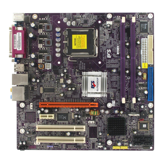
Motherboard Components Table of Motherboard Components LABEL COMPONENTS ® ® LGA775 socket for Intel Core 2 Duo/Pentium 1. CPU Socket ® ® /Pentium 4/Celeron D CPUs 2. CPU_FAN CPU cooling fan connector 240-pin DDR2 SDRAM slots 3. DIMM1~2 4. IRDA Infrared header 5. - Page 12 Memo Introducing the Motherboard...
-
Page 13: Installing The Motherboard
Chapter 2 Installing the Motherboard Safety Precautions • Follow these safety precautions when installing the motherboard • Wear a grounding strap attached to a grounded device to avoid dam- age from static electricity • Discharge static electricity by touching the metal case of a safely grounded object before working on the motherboard •... -
Page 14: Checking Jumper Settings
Do not over-tighten the screws as this can stress the motherboard. Checking Jumper Settings This section explains how to set jumpers for correct configuration of the motherboard. Setting Jumpers Use the motherboard jumpers to set system configuration options. Jumpers with more than one pin are numbered. -
Page 15: Checking Jumper Settings
Checking Jumper Settings The following illustration shows the location of the motherboard jumpers. Pin 1 is labeled. Jumper Settings Type Description Jumper Setting (default) 1-2: NORMAL 2-3: CLEAR CMOS CLR_CMOS 3-pin CLR_CMOS Before clearing the CMOS, make sure to CLR_CMOS turn off the system. -
Page 16: Installing Hardware
Installing Hardware Installing the Processor Caution: When installing a CPU heatsink and cooling fan make sure that you DO NOT scratch the motherboard or any of the surface- mount resistors with the clip of the cooling fan. If the clip of the cooling fan scrapes across the motherboard, you may cause serious damage to the motherboard or its components. -
Page 17: Cpu Installation Procedure
CPU Installation Procedure The following illustration shows CPU installation components. Read and follow the instructions shown on the sticker on the CPU cap. B. Unload the cap · Use thumb & forefinger to hold the lifting tab of the cap. ·... -
Page 18: Installing Memory Modules
Installing Memory Modules This motherboard accommodates two memory modules. It can support two 240-pin DDR2 667/533/400. The total memory capacity is 2 GB. DDR2 SDRAM memory module table Memory module Memory Bus DDR2 400 200 MHz DDR2 533 266 MHz DDR2 667 333 MHz You must install at least one module in any of the two slots. - Page 19 Table A: DDR2(memory module) QVL (Qualified Vendor List) The following DDR2 667/533/400 memory modules have been tested and qualified for use with this motherboard. Type Size Vendor Module Name Samsung K4T51163QB-ZCCC DDR2 400 256 MB Samsung K4T51083QB-GCCC 512 MB Twinmos Samsung K4T51083QB-GCCC Corsair 4PB11D9CHM...
-
Page 20: Expansion Slots
Expansion Slots Installing Add-on Cards The slots on this motherboard are designed to hold expansion cards and connect them to the system bus. Expansion slots are a means of adding or enhancing the motherboard’s features and capabilities. With these efficient facilities, you can in- crease the motherboard’s capabilities by adding hardware that performs tasks that are not part of the basic system. - Page 21 Follow these instructions to install an add-on card: Remove a blanking plate from the system case corresponding to the slot you are going to use. Install the edge connector of the add-on card into the expansion slot. Ensure that the edge connector is correctly seated in the slot. Secure the metal bracket of the card to the system case with a screw.
-
Page 22: Connecting Optional Devices
Connecting Optional Devices Refer to the following for information on connecting the motherboard’s optional devices: SATA1~4: Serial ATA connectors These connectors are use to support the new Serial ATA devices for the highest date transfer rates (3.0 Gb/s), simpler disk drive cabling and easier PC assembly. It elimi- nates limitations of the current Parallel ATA interface. - Page 23 F_AUDIO: Front Panel Audio header for Azalia This header allows the user to install auxiliary front-oriented microphone and 6/8- channel (optional) line-out ports for easier access. Signal Name Function Signal Name AUD_MIC Front Panel Microphone input signal AUD_GND Ground used by Analog Audio Circuits MIC_BIAS Microphone Power AUD_VCC...
- Page 24 WOL1: Wake On LAN connector (optional) If you have installed a LAN card, use the cable provided with the card to plug into the WOL connector onboard. This enables the Wake On LAN (WOL) feature. When your system is in a power-saving mode, any LAN signal automatically resumes the system.
- Page 25 USB1~2: Front Panel USB headers The motherboard has four USB ports installed on the rear edge I/O port array. Additionally, some computer cases have USB ports at the front of the case. If you have this kind of case, use auxiliary USB connector to connect the front-mounted ports to the motherboard.
- Page 26 JLPC(Low pin count header ) (optional) Signal Name Signal Name CK_P_33M_JLPC FWH4 PCIRST_L1 SMBDATA FWH3 FWH2 VCC3 FWH1 FWH0 PENABLE 3VSBY SIRQ LPCPD_L SMBCLK SPDIFO: SPDIF out header (optional) This is an optional header that provides an SPDIFO (Sony/Philips Digital Interface) output to digital multimedia device through optical fiber or coaxial connector.
-
Page 27: Installing A Hard Disk Drive/Cd-Rom/Sata Hard Drive
Installing a Hard Disk Drive/CD-ROM/SATA Hard Drive This section describes how to install IDE devices such as a hard disk drive and a CD- ROM drive. About IDE Devices Your motherboard has one IDE channel interface. An IDE ribbon cable supporting two IDE devices is bundled with the motherboard. -
Page 28: Installing A Floppy Diskette Drive
Refer to the illustration below for proper installation: Attach either cable end to the connector on the motherboard. Attach the other cable end to the SATA hard drive. Attach the SATA power cable to the SATA hard drive and connect the other end to the power supply. -
Page 29: Connecting I/O Devices
Connecting I/O Devices The backplane of the motherboard has the following I/O ports: PS2 Mouse Use the upper PS/2 port to connect a PS/2 pointing device. PS2 Keyboard Use the lower PS/2 port to connect a PS/2 keyboard. Parallel Port Use LPT to connect printers or other parallel communica- (LPT) tion devices. - Page 30 This motherboard may adopt 6-channel audio ports. Use the three audio ports to connect audio de- vices. The first jack is for stereo line-in signal. The second jack is for stereo line-out signal. The third jack is for microphone. Installing the Motherboard...
-
Page 31: Connecting Case Components
Connecting Case Components After you have installed the motherboard into a case, you can begin con- necting the motherboard components. Refer to the following: Connect the CPU cooling fan cable to CPU_FAN. Connect the system cooling fan connector to SYS_FAN. Connect the case switches and indicator LEDs to the PANEL1. - Page 32 CPU_FAN: FAN Power Connector Signal Name Function System Ground Power +12V +12V Sense Sensor CPU FAN control Users please note that the fan connector supports the CPU cooling fan of 1.1A ~ 2.2A (26.4W max) at +12V. SYS_FAN/CHS_FAN: FAN Power Connector (optional) Signal Name Function System Ground...
-
Page 33: Front Panel Header
Front Panel Header The front panel header (PANEL1) provides a standard set of switch and LED headers commonly found on ATX or Micro ATX cases. Refer to the table below for informa- tion: Signal Function Signal Function HD_LED_P Hard disk LED(+) FP PWR/SLP *MSG LED(+) HD_LED_N Hard disk LED(- ) FP PWR/SLP *MSG LED(-) - Page 34 Memo Installing the Motherboard...
-
Page 35: Using Bios
Chapter 3 Using BIOS About the Setup Utility The computer uses the latest Award BIOS with support for Windows Plug and Play. The CMOS chip on the motherboard contains the ROM setup instructions for con- figuring the motherboard BIOS. The BIOS (Basic Input and Output System) Setup Utility displays the system’s configuration status and provides you with options to set system parameters. -
Page 36: Using Bios
Pressing the delete key accesses the BIOS Setup Utility: Phoenix-AwardBIOS CMOS Setup Utility: Standard CMOS Features Frequency/Voltage Control Advanced BIOS Features Load Fail-Safe Defaults Advanced Chipset Features Load Optimized Defaults Integrated Peripherals Set Supervisor Password Power Management Setup Set User Password PnP/PCI Configurations Save &... -
Page 37: Standard Cmos Features
For the purpose of better product maintenance, the manufacture reserves the right to change the BIOS items presented in this manual. The BIOS setup screens shown in this chapter are for reference only and may differ from the actual BIOS. Please visit the manufacture’s website for updated manual. Standard CMOS Features This option displays basic information about your system. - Page 38 IDE HDD Auto-Detection Press <Enter> while this item is highlighted to prompt the Setup Utility to automatically detect and configure an IDE device on the IDE channel. If you are setting up a new hard disk drive that supports LBA mode, more than one line will appear in the parameter box.
-
Page 39: Advanced Bios Features
Advanced BIOS Features This option defines advanced information about your system. Phoenix-AwardBIOS CMOS Setup Utility Advanced BIOS Features CPU Feature [Press Enter] Item Help Hard Disk Boot Priority [Press Enter] CPU L1 & L2 Cache [Enabled] Menu Level CPU L3 Cache [Enabled] Hyper-Threading Technology [Enabled]... - Page 40 TM2 Bus Ratio (0X) This item represents the frequency (bus ratio) of the throttled performance state that will be initiated when the on-die sensor goes from not hot to hot). TM2 Bus VID (0.8375V) This item represents the voltage of the throttled performance state that will be initiated when the on-die sensor goes from not hot to hot.
- Page 41 CPU L3 Cache (Enabled) This item is only available when processors support L3. Some high-end processors support L3. If the CPU do support L3, you may set this item to enable or disable. Leave this item at the default value for better performance. Hyper-Threading Technology (Enabled) This item is only available when the chipset supports Hyper-Threading and you are using a Hyper-Threading CPU.
-
Page 42: Advanced Chipset Features
APIC Mode (Enabled) This item allows you to enable or disable the APIC (Advanced Programmable Interrupt Controller) mode. APIC provides symmetric multi-processing (SMP) for systems, allowing support for up to 60 processors. OS Select For DRAM > 64 MB (Non-OS2) This item is only required if you have installed more than 64 MB of memory and you are running the OS/2 operating system. - Page 43 CAS Latency Time (Auto) When synchronous DRAM is installed, the number of clock cycles of CAS latency depends on the DRAM timing. Do not reset this field from the default value specified by the system designer. DRAM RAS# to CAS# Delay (Auto) This field allows you insert a timing delay between the CAS and RAS strobe signals, used when DRAM is written to, read from, or refreshed.
-
Page 44: Integrated Peripherals
Integrated Peripherals These options display items that define the operation of peripheral components on the system’s input/output ports. Phoenix-AwardBIOS CMOS Setup Utility Integrated Peripherals Item Help OnChip IDE Device [Press Enter] Onboard Device [Press Enter] Menu Level SuperIO Device [Press Enter] : Move Enter: Select +/-/PU/PD:Value F10:Save ESC:Exit F1: General Help F5:Previous Values F6:Fail-Safe Defaults... - Page 45 IDE DMA transfer Access (Enabled) This item allows you to enabled the transfer access of the IDE DMA. On-Chip Primary/Secondary PCI IDE (Enabled) The integrated peripheral controller contains an IDE interface with support for two IDE channels. Select Enabled to activate each channel separately. IDE Primary/Secondary Master/Slave PIO (Auto) Each IDE channel supports a master device and a slave device.
- Page 46 Onboard Device (Press Enter) Scroll to this item and press <Enter> to view the following screen: Phoenix-AwardBIOS CMOS Setup Utility Onboard Device USB Controller [Enabled] Item Help USB 2.0 Controller [Enabled] USB Keyboard Support [Enabled] Menu Level USB Mouse Support [Enabled] Azalia/AC97 Audio Select [Auto]...
- Page 47 SuperIO Device (Press Enter) Scroll to this item and press <Enter> to view the following screen: Phoenix-AwardBIOS CMOS Setup Utility SuperIO Device Item Help PS2 POWER ON Function [Hot Key] Hot Key Power ON [Ctrl-F12] Onboard FDC Controller [Enabled] Menu Level Onboard Serial Port 1 [3F8/IRQ4] UART 2 Mode Controller...
-
Page 48: Power Management Setup
Parallel Port Mode (ECP) Enables you to set the data transfer protocol for your parallel port. There are four options:SPP (Standard Parallel Port), EPP (Enhanced Parallel Port), ECP (Extended CapabilitiesPort), and ECP+EPP. SPP allows data output only. Extended Capabilities Port (ECP) and Enhanced Paral- lel Port (EPP) are bi-directional modes, allowing both data input and output. - Page 49 PCI Express PM Function (Press Enter) This item allows you to enable or disable the PCI Express PM Function. ACPI Suspend Type (S3(STR)) Use this item to define how your system suspends. In the default, S3 (STR), the suspend mode is a suspend to RAM, i.e., the system shuts down with the exception of a refresh current to the system memory.
-
Page 50: Pnp/Pci Configurations
Resume by Alarm (Disabled) When set to Enabled, additional fields become available and you can set the date (day of the month), hour, minute and second to turn on your system. When set to 0 (zero) for the day of the month, the alarm will power on your system every day at the specified time. -
Page 51: Pc Health Status
Init Display First (PCI Slot) This item allows you to choose the primary display card. Reset Configuration Data (Disabled) If you enable this item and restart the system, any Plug and Play configuration data stored in the BIOS Setup is cleared from memory. Resources Controlled By Auto (Auto (ESCD)) You should leave this item at the default Auto (ESCD). -
Page 52: Frequency Control
Shutdown Temperature (Disabled) Enables you to set the maximum temperature the system can reach before powering down. System Component Characteristics These fields provide you with information about the systems current operating status. You cannot make changes to these fields. • Vcore •... -
Page 53: Load Fail-Safe Defaults Option
CPU Clock Ratio (8X) Enables you to set the CPU clock. The CPU clock ratio times the CPU Host/PCI Clock should equal the core speed of the installed processor. Example: CPU Clock Ratio CPU Frequency Installed CPU Clock Speed 3200 MHz Auto Detect PCI Clk (Enabled) When this item is enabled, BIOS will disable the clock signal of free DIMM and PCI slots. -
Page 54: Set Password
Set Supervisor/User Password When this function is selected, the following message appears at the center of the screen to assist you in creating a password. ENTER PASSWORD Type the password, up to eight characters, and press <Enter>. The password typed now will clear any previously entered password from CMOS memory. You will be asked to confirm the password. -
Page 55: Updating The Bios
Updating the BIOS You can download and install updated BIOS for this motherboard from the manufacturer’s Web site. New BIOS provides support for new peripherals, improve- ments in performance, or fixes for known bugs. Install new BIOS as follows: If your motherboard has a BIOS protection jumper, change the setting to allow BIOS flashing. - Page 56 Memo Using BIOS...
-
Page 57: Using The Motherboard Software
Chapter 4 Using the Motherboard Software About the Software CD-ROM The support software CD-ROM that is included in the motherboard package contains all the drivers and utility programs needed to properly run the bundled products. Below you can find a brief description of each software program, and the location for your motherboard version. -
Page 58: Running Setup
Setup Tab Setup Click the Setup button to run the software installation program. Select from the menu which software you want to install. Browse CD The Browse CD button is the standard Windows command that allows you to open Windows Explorer and show the contents of the support CD. - Page 59 Click Next. The following screen appears: Check the box next to the items you want to install. The default options are recommended. Click Next run the Installation Wizard. An item installation screen appears: Follow the instructions on the screen to install the items. Drivers and software are automatically installed in sequence.
-
Page 60: Manual Installation
Manual Installation Insert the CD in the CD-ROM drive and locate the PATH.DOC file in the root directory. This file contains the information needed to locate the drivers for your motherboard. Look for the chipset and motherboard model; then browse to the directory and path to begin installing the drivers.
Need help?
Do you have a question about the 945GCT-M3 and is the answer not in the manual?
Questions and answers