Table of Contents
Advertisement
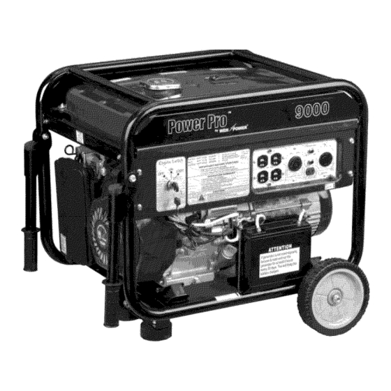
MODEL 9000
16 HP Generator
Item # 56900
Owner's
Manual
Manual
del Propietario
DO NOT RETURN
TO STORE
Questions?
Problems?
Please call our customer
help line:
(800)
232-1195
M-F 8-5 CT
Thank you for purchasing
a model 9000 generator.
This manual provides
information
regarding
the
operation and maintenance
of this product. We have made every effort to ensure the accuracy of the
information
in this manual. Wen Power
TM
reserves the right to change this product at any time
without prior notice.
Please keep this manual available to all users during the entire life of the generator.
04/06
Advertisement
Table of Contents

Related Manuals for WEN POWER Power Pro 9000


Summary of Contents for WEN POWER Power Pro 9000
- Page 1 We have made every effort to ensure the accuracy of the information in this manual. Wen Power reserves the right to change this product at any time without prior notice. Please keep this manual available to all users during the entire life of the generator.
- Page 2 MODEL 9000 16 HP Generator FEATURES • 9000 Surge Watt Output • 7500 Maximum Watt Output • 6500 Rated Watt Output • Powerful Enough to Run Essential Appliances During Power Outages • 120 and240 VoltAC Outputs" • 12V/8.3A DC Output •...
-
Page 3: Table Of Contents
..............................EXPLODED VIEW AND PARTS LIST ..........................WIRING DIAGRAM ........................ Error! Bookmark not defined. LIMITED WARRANTY FOR POWER PRO GENERATORS FROM WEN POWER ........NOTICE REGARDING EMISSIONS Engines that are certified to comply with U.S. EPA emission regulations for SORE (Small Off Road... -
Page 4: General Safety Procedures
GENERAL SAFETY PROCEDURES Please familiarize yourself with the following safety symbols and words: The safety alert symbol ,/k is used with one of the safety words (DANGER, CAUTION, WARNING) to alert user to hazards. Please pay attention to these hazard notices both in this manual and on the generator. - Page 5 aX WARNING: This generator may emit highly flammable and explosive gasoline vapors, which can cause severe burns or even death. A nearby open flame can lead to explosion even if not directly in contact with gas. • Do not operate near open flame. •...
- Page 6 aX WARNING: This generator produces heat when running. Temperatures near exhaust can exceed 150 ° F (65 ° C). • Do not touch hot surfaces. Pay attention to warning labels on the generator denoting hot parts of the machine. • Allow generator to cool several minutes after use before touching engine or...
- Page 7 In additionto the abovesafetynotices, p leasefamiliarizeyourselfwith the safetyandhazardmarkings on the generator.
-
Page 8: Package Contents
PACKAGE CONTENTS This generator comes with the items listed below. Please check to see that all of the following items are included with the generator. _W If there are missing components DO NOT RETURN TO STORE, please call (800) 232- 1195 8-5 CT for customer service. -
Page 9: Generator Components
GENERATOR COMPONENTS Please familiarize yourself with the locations and functions of the various components and controls of this generator. (1) Fuel Gauge- Indicates the amount of fuel in the tank. (2) Fuel Cap- Access to the fuel tank for adding fuel. (3) Choke Lever- Adjusts the amount of air let into the engine. -
Page 10: Assembly
ASSEMBLY In order to best protect the generator while in the package, this product comes with the wheels and handles disassembled. Please complete the following assembly steps before proceeding to use the generator. For ease of assembly, we recommend attaching the components in the order listed below. -
Page 11: Attach Wheels
Attach Wheels The wheels attach to the opposite side of the generator from the handles. To attach the wheels: 1. Place the generator on support blocks such as a scrap piece of wood (see figure 2). 2. Attach the wheel axle to the generator. Slide the axle underneath the generator frame. Align the holes on the axle with the holes on the bottom cross beam of the generator frame. -
Page 12: Preparing The Generator For Use
FOOT INSTALLED FOOT Figure 3- Installing foot bracket PREPARING THE GENERATOR FOR USE Usin_ the Generator for the First Time The following section describes steps user must follow to prepare the generator for the first-time usage. If after reading this section, you are unsure about how to perform any of the steps please call (800) 232-1195... -
Page 13: Step 2- Add Oil
The generator comes with the battery disconnected for safety. To use the electric start, the battery need to be connected. To connect the battery: 1. Remove the protective covering from the free end of the negative battery cable. This cable is connected to the generator on the other end and is located in the vicinity of the battery. -
Page 14: Step
• Always operate on a firm, level surface. • Always turn generator off before refueling. Allow generator to cool for at least 2 minutes before removing fuel cap. Loosen cap slowly to relieve pressure in tank. • Do not overfill gas tank. -
Page 15: Subsequent Use Of The Generator
Te_in_ with Tightening Nut Figure 6- Grounding nut location Subsequent Use of the Generator If this is not your first time using the generator there are still steps you should take to prepare it for operation. IMPORTANT: At this point you should be familiar with the procedures described in the first portion of this section entitled "Using the Generator... -
Page 16: Step 3- Ground The Generator
• Do not fill tank near an open flame. • Always allow engine to cool for several minutes before refueling. • Do not overfill (check the "Specifications" section for the tank capacity of this generator). Always check for fuel spills. IMPORTANT: •... -
Page 17: Starting The Generator
STARTING THE GENERATOR 'W _Before starting the generator, make sure you have read and performed the steps in the "Preparing the Generator for Use" section of this manual. If you are unsure about how to perform any of the steps in this manual please call (800) 232-1195 8-5 CT for customer... -
Page 18: Manual Start
7. Turn the enginekey to the "start" positionfor 2-3 seconds or until the enginestarts.NOTE: If the enginedoesnot startafter 2-3 seconds, release the key from the start position. Keeping key in the start position too long can damage the starter. If engine fails to start, wait 10 seconds, then repeat... - Page 19 CHOKE OPEN CLOSE Figure 8- Choke positions Figure 7- Fuel valve positions STARTER GRI P Figure 9- Pulling the start cord...
-
Page 20: Using The Generator
USING THE GENERATOR A WARNING: Never connect a generator directly to any existing electrical building circuit. The generator can backfeed into power lines and electrocute nearby electrical repair workers. Once you have allowed the engine to mn for several minutes, you may connect electrical devices to the generator. - Page 21 CAUTION- The generator can run at its surge wattage capacity for only a short time. Connect electrical devices requiring a rated (running) wattage equal to or less than the rated wattage of the generator. Never connect devices requiring a rated wattage equal to the surge wattage of the generator.
-
Page 22: Dc Usage
CAUTION: Do not connect 50Hz or 3-phase loads to the generator. 120V Receptacle Power Indicator Circuit Protector 240/120V Engine Switch Receptacle 120V Receptacle 120V Receptacle 12V/8.3A Ground Terminal Figure 12- Receptacles available on the generator SOME NOTES ABOUT POWER CORDS Long or thin cords can drain the power provided to an electrical device by the generator. -
Page 23: Stopping The Generator
STOPPING THE GENERATOR To stop the generator: 1. Turn off, then unplug all connected electrical devices. Allow the generator to run for several more minutes with no electrical devices connected. This helps stabilize the temperature of the generator. Turn the engine switch key to the "off" position. Remove the key. Turn the fuel valve to the "off"... -
Page 24: Cleaning The Generator
Cleanin_ the Generator Always try to use your generator in a cool dry place. In the event your generator becomes dirty you may clean the exterior with one or more of the following: a damp cloth a soft brush a vacuum pressurized Never clean your generator with a bucket of water or a hose. -
Page 25: Air Cleaner Maintenance
It is necessary to drain the oil from the crankcase after 50 hrs of use, or if it has become contaminated with water or dirt. In this case, you can drain the oil from the generator according to the following steps: Place a bucket underneath the generator to catch oil as it drains. -
Page 26: Fuel Filter Cup Cleaning
AiR CL_NER COVER ELEMENT Figure 18- Removing the air cleaner casing. Fuel Filter Cup Cleanin_ The fuel filter cup is a small well underneath the fuel valve. It helps to trap dirt and water that may be in your fuel tank before it can enter the engine. To clean the fuel filter cup: 1. -
Page 27: Spark Plug Maintenance
Spark Plu_ Maintenance The spark plug is important for proper engine operation. A good spark plug should be intact, free of deposits, and properly gapped. To inspect your spark plug: 1. Pull on the spark plug cap to remove it. Unscrew the spark plug from the generator using the spark plug wrench included with this product (see figure 20).Visually inspect the spark plug. -
Page 28: Changing The Battery
Chan_in_ the Battery /_ WARNING: Battery gives off explosive hydrogen • Keep battery away from spark, flame, or cigarette. • Do not connect or disconnect battery while generator is running. • Service or use battery only in well ventilated areas. WARNING: Battery contains sulfuric acid. -
Page 29: Specifications
SPECIFICATIONS Generator AC Output Rated Wattage 6500 W Maximum Wattage 7500 W Surge Wattage 9000 W Rated Voltage 240V 120V Rated Amperage 27A/54A Rated Frequency 60 Hz Phase Single DC Output Rated Voltage 12 V Rate d Amperage 8.3 A length = 28.7 Dimensions (in):... -
Page 30: Troubleshooting
TROUBLESHOOTING IMPORTANT: If trouble persists please call our customer help line at (800) 232-1195 M-F 8-5 Central Time. Problem Cause Solution Engine will not start Engine switch is set to "off". Set engine switch to "on". No fuel in carburetor Turn fuel valve handle to up/down... - Page 32 Item Part Item Part Description Description 100000-248-1 080265-100-1 M10 X 265 bolt 16 hp gasoline engine 227100-225-1 Tubular frame SB06H9 M6 X 179 bolt 227351-248-1 080712-100-1 Washer Left rubber damper 227352-248-1 228001-248-1 Right rubber damper Generator stay MS1000 M10 nut 214252-248-1 Gas cap 35513-1...
- Page 33 ©...
-
Page 35: Limited Warranty For Power Pro
Power Pro by WEN Power T`'is not liable for any indirect, incidental or consequential damages from the sale or use of this product. Any implied warranties are limited to one (1) year as stated in this written limited warranty.
Need help?
Do you have a question about the Power Pro 9000 and is the answer not in the manual?
Questions and answers
find out age by serial number?