Advertisement
Quick Links
Advertisement

Related Manuals for Cerwin-Vega CXA series


Summary of Contents for Cerwin-Vega CXA series
- Page 1 CXA - AMPLIFIER SERIES OPERATION MANUAL...
- Page 2 Cerwin-Vega! CXA - AMPLIFIER SERIES Read Instructions – All the safety and operating instructions should be read before this product is operated. Retain Instructions – The safety and operating instructions should be retained for future reference. Heed Warnings – All warnings on the appliance and in the operating instructions should be adhered to.
-
Page 3: Unpacking And Installation
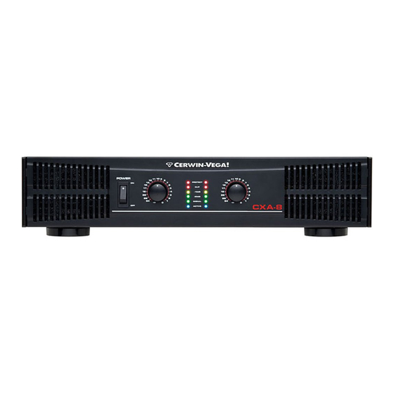
ABOUT THE CERWIN-VEgA! CXA AMPLIFIER SERIES The Cerwin-Vega! CXA-Series high performance stereo and bridgeable power amplifiers are for those that want to sound like a pro! These home-use versions of the renowned Cerwin-Vega! Professional series amplifiers. The same capability for shock and awe, but with input/output connections and a form factor suited for performing at home versus on stage. - Page 4 Cerwin-Vega! CXA - AMPLIFIER SERIES CXA AMPLIFIER FRONT PANEL DESCRIPTION Figure 1.1 1. Fan Vent 5. Active Indicators The CV-Series amplifiers are cooled by two rear-mounted fans These blue LED's indicate that AC power is connected and the (except for CV-900 which is cooled by a single rear mounted fan).
- Page 5 Cerwin-Vega! CXA - AMPLIFIER SERIES CXA AMPLIFIER REAR PANEL DESCRIPTION Figure 1.2 1. Fan 6. Bridge / Stereo / Parallel switch This is a variable speed cooling fan. Cool air enters the amplifier This switch changes the amplifier operating mode between through the fan filters located on the front of the amplifier.
- Page 6 PROTECTION Every model in the CV-Series incorporates protection features. Short circuit : If output is shorted due to faulty wiring, the The front panel Protection LED indicates the activity of the thermal circuitry will automatically protect the amplifier. If this speaker connection relay circuitry in each channel.When the occurs, the load will be disconnected by the thermal protection protection LED turns on, this circuitry is active, and all connected...
- Page 7 SETUP (CONTINUED) CONNECTIONS Mode Select Stereo Mode (5-Way Ouptut Binding Posts) Stereo Mode In stereo mode, both channels operate independently with in- dividual input gain controls. Signal at channel 1’s input produces output at channel 1, while signal at channel 2’s input produces output at channel 2’s output.
- Page 8 Cerwin-Vega! CXA - AMPLIFIER SPECIFICATIONS CXA-8 CXA-10 Output Power (RMS) Stereo Both Channels Driven 8 ohms 400 W 600 W 4 ohms 600 W 900 W 2 ohms 900 W 1400 W Output Power (RMS) Bridged Mono 8 ohms 1200 W...
- Page 9 772 S. Military Trail • Deerfield Beach, FL 33442 Phone: +1 (954) 949-9601 Fax: +1 (954) 949-9590 E-mail: info@cerwin-vega.com www.cerwin-vega.com LITH00023 CXA OWNERS MANUAL...
Need help?
Do you have a question about the CXA series and is the answer not in the manual?
Questions and answers