Innova OBD2 Owner's Manual
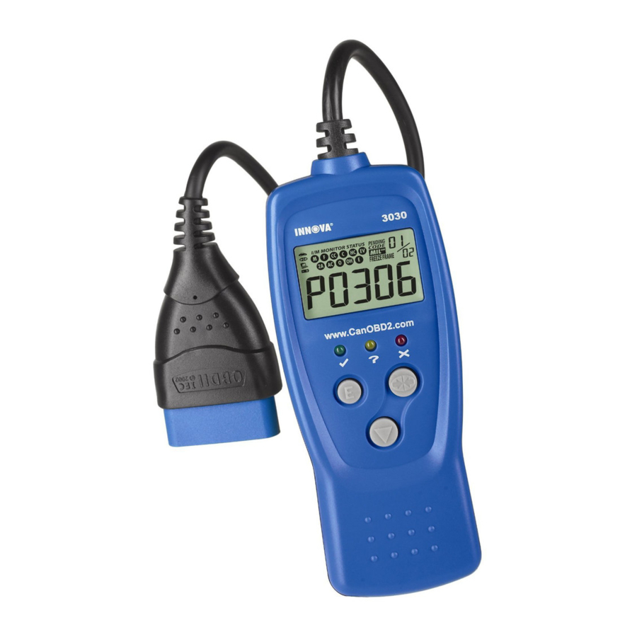
Digital car reader
Hide thumbs
Also See for OBD2:
- Owner's manual (138 pages) ,
- Owner's manual (56 pages) ,
- Owner's manual (72 pages)
Table of Contents
Advertisement
Advertisement
Table of Contents

Related Manuals for Innova OBD2


Summary of Contents for Innova OBD2
- Page 1 ER'S...
- Page 2 Title Page No. YOU CAN DO IT! ..........SAFETY PRECAUTIONS Safety First ..........ABOUT THE CAR READER Vehicles Covered ........Controls and Indicators ........Display Functions ........PREPARATION FOR TESTING Before You Begin ......... Vehicle Service Manuals ........USING THE CODE READER Code Retrieval Procedure...
- Page 3 Easy To Use ..• Connect the Car Reader to the vehicle's test connector. • Turn the ignition key "On." DO NOT start engine. • Reader will automatically link to the vehicle's computer. Easy To View ..• Reader retrieves stored codes displays...
- Page 4 SAFETY FIRST! This manual describes common test procedures used by experienced service technicians. Many test procedures require precautions to avoid accidents that can result in personal injury, and/or damage to your vehicle or test equipment. Always read your vehicle's service manual and follow its safety...
-
Page 5: Vehicles Covered
VEHICLES COVERED The Car Reader is designed to work on all OBD 2 compliant vehicles. All 1996 and newer vehicles (cars and light trucks) sold in the United States are OBD 2 compliant. This includes all Domestic, Asian and European vehicles. -
Page 6: Controls And Indicators
CONTROLS AND INDICATORS o°o°o°o oooo oooo oooo Figure 1. Controls and Indicators See Figure 1 for the locations of items 1 through 9, below. 1. _ ERASE button - Erases Diagnostic Trouble Codes (DTCs) and "Freeze Frame" data from your vehicle's computer, and resets Monitor status. -
Page 7: Display Functions
6. X RED LED - Indicates there is a problem in one or more of the vehicle's systems. The red LED is also used to show that DTC(s) are present. DTCs are shown on the Car Reader's LCD display. In this case, the Multifunction Indicator ("Check Engine") - Page 8 8. Code Number Sequence - The Car Reader assigns a sequence number each DTC that is present in the computer's memory, starting with "01 ." This helps keep track of the number of DTCs present in the computer's memory. Code number "01"...
- Page 9 BEFORE YOU BEGIN Fix any known mechanical problems before performing any test. See your vehicle's service manual or a mechanic for more information. Check the following areas before starting any test: • Check the engine oil, power steering fluid, transmission fluid (if applicable), engine coolant and other fluids for proper levels.
-
Page 10: Code Retrieval Procedure
CODE RETRIEVAL PROCEDURE Never replace a part based only on the DTC definition. Each DTC has a set of testing procedures, instructions and flow charts that must be followed to confirm the location of the problem. This information is found in the vehicle's service manual. - Page 11 Turn the ignition key off, wait 5 seconds and turn the key back on to reset the computer. Make sure your vehicle is OBD 2 compliant. See VEHICLES COVERED on page 2 for vehicle compliance verification information. 6. Read and interpret the Diagnostic Trouble Codes using the LCD display and the green, yellow and red LEDs.
-
Page 12: Erasing Diagnostic Trouble Codes
Reader will automatically re-link to the vehicle's computer every 15 seconds to refresh the data being retrieved. When data is being refreshed, a single beep will sound, "rEAd" will be shown on the LCD display for 5-6 seconds. Car Reader will then beep twice and return to displaying codes. - Page 13 3. Press and release the Car Reader's ERASE button. The LCD display will indicate "SurE" your confirmation. • If you change your mind and do not wish to erase the codes, press the LINK button to return to the code retrieval function. •...
-
Page 14: Diagnostic Trouble Code Definitions
DIAGNOSTIC TROUBLE CODE DEFINITIONS Diagnostic Trouble Codes (DTCs) are meant to guide you to the proper service procedure in the vehicle's service manual. DO NOT replace parts based only on DTCs without first consulting the vehicle's service manual for proper testing procedures for that particular... - Page 15 OBD 2 DTC EXAMPLE P0201 - InjectorCircuit Malfunction, Cylinder 1 P0201 Body Chassis P- Powertrain Network ..0 - Generic 1 - Manufacturer Specific 2 - Generic 3 - Includes both Generic and Manufacturer Specific Codes Identifies the system where the problem is located: 1 - Fuel and Air Metering 2 - Fuel and Air Metering (injector circuit...
- Page 16 Code Definition P0010 "A" Camshaft Position - Actuator Circuit (Bank 1) P0011 "A" Camshaft Position - Timing Over-Advanced or System Performance (Bank 1) P0012 "A" Camshaft Position -Timing Over-Retarded (Bank 1) P0013 "B" Camshaft Position - Actuator Circuit (Bank 1) P0014 "B"...
- Page 17 Code Definition P0076 Intake Valve Control Solenoid Circuit Low (Bank 1) P0077 Intake Valve Control Solenoid Circuit High (Bank 1 ) P0078 Exhaust Valve Control Solenoid Circuit (Bank 1) P0079 Exhaust Valve Control Solenoid Circuit Low (Bank 1) P0080 Exhaust Valve Control Solenoid Circuit High (Bank 1) P0081 Intake Valve Control Solenoid Circuit (Bank 2) P0082...
- Page 18 Code Definition P0130 02 Sensor Circuit Malfunction (Bank 1 Sensor 1) P0131 02 Sensor Circuit LowVoltage (Bank 1 Sensor 1) P0132 02 Sensor Circuit High Voltage (Bank 1 Sensor 1) P0133 02 Sensor Circuit Slow Response (Bank 1 Sensor 1) P0134 02 Sensor Circuit No Activity Detected (Bank 1 Sensor 1) P0135...
- Page 19 Code Definition P0172 System too Rich (Bank 1) P0173 Fuel Trim Malfunction (Bank 2) P0174 System too Lean (Bank 2) P0175 System too Rich (Bank 2) P0176 Fuel Composition Sensor Circuit Malfunction P0177 Fuel Composition Sensor Circuit Range/Performance P0178 Fuel Composition Sensor Circuit Low Input P0179 Fuel Composition Sensor Circuit High Input P0180...
- Page 20 Code Definition P0214 Cold Start Injector 2 Malfunction P0215 Engine Shutoff Solenoid Malfunction P0216 Injection Timing Control Circuit Malfunction P0217 Engine Overtemp Condition P0218 Transmission Over Temperature Condition P0219 Engine Overspeed Condition P0220 Throttle/Pedal Position Sensor/Switch B Circuit Malfunction P0221 Throttle/Pedal Position Sensor/Switch B Circuit Range/Performance...
- Page 21 Code Definition P0256 Injection Pump B Rotor/Cam Malfunction P0257 Injection Pump B Rotor/Cam Range/Performance P0258 Injection Pump B Rotor/Cam Low P0259 Injection Pump B Rotor/Cam High P0260 Injection Pump B Rotor/Cam Intermitted P0261 Cylinder 1 Injector Circuit Low P0262 Cylinder 1 Injector Circuit High P0263 Cylinder 1 Contribution/Balance Fault...
- Page 22 Code Definition P0300 Random/Multiple Cylinder Misfire Detected P0301 Cylinder 1 Misfire Detected P0302 Cylinder 2 Misfire Detected P0303 Cylinder 3 Misfire Detected P0304 Cylinder 4 Misfire Detected P0305 Cylinder 5 Misfire Detected P0306 Cylinder 6 Misfire Detected P0307 Cylinder 7 Misfire Detected P0308 Cylinder 8 Misfire Detected P0309...
- Page 23 Code Definition P0347 Camshaft Position Sensor "A" Circuit Low Input (Bank 2) P0348 Camshaft Position Sensor "A" Circuit High Input (Bank 2) P0349 Camshaft Position Sensor "A" Circuit Intermittent (Bank 2) P0350 Ignition Coil Primary/Secondary Circuit Malfunction P0351 Ignition Coil A Primary/Secondary Circuit Malfunction P0352 Ignition...
-
Page 24: Trouble Codes P0393-P0439
Code Definition P0393 Camshaft Position Sensor "B" Circuit High Input (Bank 2) P0394 Camshaft Position Sensor "B" Circuit Intermittent (Bank 2) P0400 Exhaust Gas Recirculation Flow Malfunction P0401 Exhaust Gas Recirculation Flow Insufficient Detected P0402 Exhaust Gas Recirculation Flow Excessive Detected P0403 Exhaust Gas Recirculation... - Page 25 Code Definition P0440 )orative Emission Control System Malfunction P0441 )orative Emission Control System Incorrect Purge Flow P0442 )orative Emission Control System Leak Detected (small leak) P0443 )orative Emission Control System Purge Control Valve Circuit Malfunction P0444 )orative Emission Control System Purge Control Valve Circuit Open P0445 )orative Emission Control System Purge Control Valve Circuit Shorted P0446...
- Page 26 Code Definition P0484 Cooling Fan Circuit Over Current P0485 Cooling Fan Power/Ground Circuit Malfunction P0486 Exhaust Gas Recirculation Sensor "B" Circuit P0487 Exhaust Gas Recirculation Throttle Position Control Circuit P0488 Exhaust Gas Recirculation Throttle Position Control Range/Performance P0491 Secondary Air Injection System (Bank 1) P0492 Secondary Air Injection System (Bank 2) P0500...
- Page 27 Code Definition P0551 Power Steering Pressure Sensor Circuit Range/Performance P0552 Power Steering Pressure Sensor Circuit Low Input P0553 Power Steering Pressure Sensor Circuit High Input P0554 Power Steering Pressure Sensor Circuit Intermittent P0560 System Voltage Malfunction P0561 System Voltage Unstable P0562 System Voltage Low P0563...
- Page 28 Code Definition P0622 Generator Field "F" Control Circuit Malfunction P0623 Generator Lamp Control Circuit P0624 Fuel Cap Lamp Control Circuit P0630 VIN Not Programmed or Mismatch - ECM/PCM P0631 VIN Not Programmed or Mismatch - TCM P0635 Power Steering Control Circuit P0636 Power Steering Control Circuit Low P0637...
- Page 29 Code Definition P0716 Input/Turbine Speed Sensor Circuit Range/Performance P0717 Input/Turbine Speed Sensor Circuit No Signal P0718 Input/Turbine Speed Sensor Circuit Intermittent P0719 Torque Converter/Brake Switch B Circuit Low P0720 Output Speed Sensor Circuit Malfunction P0721 Output Speed Sensor Circuit Range/Performance P0722 Output Speed Sensor Circuit No Signal P0723...
- Page 30 Code Definition P0759 Shift Solenoid B Intermittent P0760 Shift Solenoid C Malfunction P0761 Shift Solenoid C Performance or Stuck Off P0762 Shift Solenoid C Stuck On P0763 Shift Solenoid C Electrical P0764 Shift Solenoid C Intermittent P0765 Shift Solenoid D Malfunction P0766 Shift Solenoid D Performance or Stuck Off P0767...
- Page 31 Code Definition P0803 1-4 Upshift (Skip Shift) Solenoid Control Circuit Malfunction P0804 1-4 Upshift (Skip Shift) Lamp Control Circuit Malfunction P0805 Clutch Position Sensor Circuit P0806 Clutch Position Sensor Circuit Range/Performance P0807 Clutch Position Sensor Circuit Low P0808 Clutch Position Sensor Circuit High P0809 Clutch Position Sensor Circuit Intermittent P0810...
- Page 32 ® WEEMPLOY T ECHNICIANS CERTIFIED BY ASE ONLY. LET USSHOW YOUTHEIR CREDENTIALS. www.CanOBD2.com Innova Electronics Corp. 17291 Mt. Herrmann Street Fountain Valley, CA 92708 Printed in Taiwan Instruction MRP #93-0058...
Need help?
Do you have a question about the OBD2 and is the answer not in the manual?
Questions and answers