Table of Contents
Advertisement
Available languages
Available languages
Owner's Manual/Manual
Del Propietario
1/2 HP
:315MN= GARAGE DOOR OPENER
ABRIDOR
DE PUERTA DE COCHERA
For Residential
Use Only/Solo
para uso residencial
315MHz
Model/Modelo
139.53920DM
I"11
Z
G3
m
"0
Z_
¢3
Read and follow all safety rules and
operating
instructions
before first
use of this product.
Fasten the manual near the garage
door after installation.
Periodic checks of the opener are
required to ensure safe operation.
Leer y seguir todas las reglas de
seguridad
y las instrucciones
de
operacion
antes de usar este
producto por primera vez.
Guardar este manual cerca de la
puerta de la cochera.
Se deben realizar revisiones
periodicas
del abridor de puertas
para asegurar su operacion
segura.
Sears, Roebuck
and Co., Hoffman
Estates,
IL 60179 U.S.A
www.sears.com/craftsman
Advertisement
Chapters
Table of Contents

Related Manuals for Craftsman 139.53920DM


Summary of Contents for Craftsman 139.53920DM
- Page 1 Se deben realizar revisiones Periodic checks of the opener are periodicas del abridor de puertas required to ensure safe operation. para asegurar su operacion segura. Sears, Roebuck and Co., Hoffman Estates, IL 60179 U.S.A www.sears.com/craftsman...
-
Page 2: Table Of Contents
TABLE OF CONTENTS Introduction Adjustment 27-29 Safety symbol and signal word review ....... 2 Adjust the travel limits ..........Preparing your garage door ........Adjust the force ............Tools needed .............. Test the safety reversal system ........ Planning ..............Test The Protector System ®........Carton inventory ............ -
Page 3: Preparing Your Garage Door
Preparing your garage door Before you begin: To prevent possible SERIOUSINJURYor DEATH: • Disable locks. • ALWAYScall a trained door systems technician if garage • Remove any ropes connected to garage door. door binds, sticks, or is out of balance. An unbalanced garage door may not reverse when required. -
Page 4: Planning
Planning Do you have an access door in addition to the garage Identify the type and height of your garage door. Survey your garage area to see if any of the conditions below door? If not, Model 53702 Emergency Key Release is required. -
Page 5: Planning
Planning (Continued) ONE-PIECE DOOR INSTALLATIONS Without a properly working safety reversal system, persons (particularly small children) could be SERIOUSLYINJUREDor • Generally, a one-piece door does not require KILLED by a closing garage door. reinforcement. If your door is lightweight, refer to the •... -
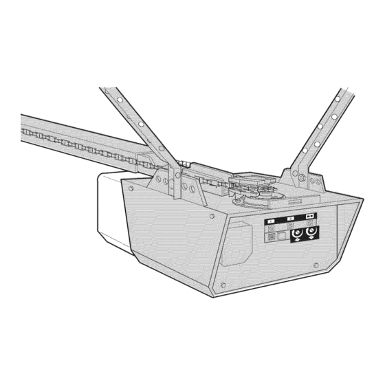
Page 6: Carton Inventory
Carton Inventory Your garage door opener is packaged in one carton which Parts may be stuck in the foam. Hardware for assembly contains the motor unit and all parts illustrated below. and installation is shown on the next page. Save the Accessories will depend on the model purchased. -
Page 7: Hardware Inventory
Hardware Inventory Separate all hardware and group as shown below for the assembly and installation procedures. ASSEMB_ HARDWARE © Lock Nut Washer 5/8" (2) Lock Washer 1/4"-20 (2) 3/8" (1) 3/8" (1) Bolt 1/4"-20xl-3/4" Master Link (2) Bolt 1/4"-20x2-1/2 Spacer (2) Idler Bolt (1) ©... - Page 8 ASSEMBLY STEP Assemble the Rail & Install the Trolley To prevent INJURY from pinching, keep hands and fingers away from the joints while assembling the rail. To avoid installation difficulties, do not run the garage door opener until instructed to do so. The front rail has a cut out "window"at the door end (see 3.
-
Page 9: Assembly
ASSEMBLY STEP Fasten the Rail to the Motor Unit To avoid SERIOUSdamage to garage door opener, use ONLY those bolts/fasteners mounted in the top of the opener. • Insert a 1/4"-20x2-1/2 bolt, washer and spacer into the cover protection bolt hole on the back end of the rail as shown. -
Page 10: Install The Chain/Cable
ASSEMBLY STEP Install Chain/Cable To avoid possible SERIOUSINJURYto fingers from moving garage door opener: 1. Pull the cable around the idler pulley and toward the • ALWAYSkeep hand clear of sprocket while operating trolley. opener. 2. Connect the cable to the retaining slot on the trolley, as •... -
Page 11: Tighten The Chain
ASSEMBLY STEP Tighten Chain Figure 1 Trolley • Spin the inner nut and lock washer down the trolley Outer Lock Threaded threaded shaft, away from the trolley. Washer Shaft To Tighten Outer Nut • To tighten the chain, turn outer nut in the direction shown (Figure 1). -
Page 12: Determine The Header Bracket Location
INSTALLATION STEP Determine Header Bracket Location Header Wall To prevent possible SERIOUSINJURYor DEATH: • Header bracket MUSTbe RIGIDLY fastenedto structural support on header wall or ceiling, otherwise garage door might not reversewhen required. DO NOT install header bracket over drywall. •... -
Page 13: Install The Header Bracket
INSTALLATION STEP Wall Mount Install Header Bracket You can attach the header bracket either to the wall above the garage door, or to the ceiling. Follow the instructions which will work best for your particular requirements. not install the header bracket over drywall. -
Page 14: Attach The Rail To The Header Bracket
INSTALLATION STEP Attach the Rail to the Header Bracket NOTE: (Optional) With some existing installations, you may re-use the old header bracket with the two plastic spacers included in the hardware bag. Place the spacers inside the bracket on each side of the rail, as illustrated. •... -
Page 15: Position The Opener
INSTALLATION STEP Position Opener To prevent damageto garage door, rest garage door opener rail on 2x4 placed on top section of door. Follow instructions which apply to your door type as illustrated. SECTIONAL DOOR OR ONE-PIECE DOOR WITH TRACK A 2x4 laid flat is convenient for setting an ideal door-to-rail distance. -
Page 16: Hang The Opener
INSTALLATION STEP Hang Opener To avoid possible SERIOUSINJURY from a failing garage door opener, fasten it SECURELY to structural supports of the Three representative installations are shown. Yours may garage. Concreteanchors MUST be used if installing any be different. Hanging brackets should be angled (Figure 1) brackets into masonry. -
Page 17: Install The Door Control
INSTALLATION STEP Install Door Control To prevent )ossible SERIOUSINJURYor DEATHfrom electrocution: Locate door control within sight of door, at a minimum height of 5 feet (1.5 m) where small children cannot reach, • Be sure power is not connected BEFORE installing door control. -
Page 18: Install The Light
INSTALLATION STEP Install Light To prevent possible OVERHEATING of the endpanel or light socket: • Install a 75 watt maximum light bulb in the socket. Light • DO NOT use short neck or specialty light bulbs. bulb size should be A19, standard neck only. The light •... -
Page 19: Electrical Requirements
INSTALLATION STEP Electrical Requirements To prevent possible SERIOUSINJURYor DEATHfrom electrocution or fire: To avoid installation difficulties, do not run the opener • Be sure power is not connected to the opener, and at this time. disconnect power to circuit BEFORE removing cover to To reduce the risk of electric shock, your garage door establish permanent wiring connection. -
Page 20: Install The Protector System
INSTALLATION STEP Install The Protector System ® Be sure power is not connected to the garage door opener BEFORE installing the safety reversing sensor. The safety reversing sensor must be connected and To prevent SERIOUSINJURY or DEATHfrom a closing garage aligned correctly before the garage door opener will door: move in the down direction. - Page 21 INSTALLING THE BRACKETS Figure DOOR TRACK MOUNT (RIGHT SIDE) Be sure power to the opener is disconnected. Install and align the brackets so the sensors will face each other Door across the garage door, with the beam no higher than 6" Track (15 cm) above the floor.
- Page 22 MOUNTING AND WIRING THE SAFETY REVERSING Figure 5 SENSORS Wing Nut • Slide a 1/4"-20xl/2" carriage bolt head into the slot on each sensor. Use wing nuts to fasten sensors to brackets, with lenses pointing toward each other across the door. Be sure the lens is not obstructed by a bracket OarriageBo,t extension (Figure 5).
-
Page 23: Fasten The Door Bracket
INSTALLATION STEP Fasten the Door Bracket Fiberglass, aluminum or lightweight steel garage doors WILL REQUIREreinforcement BEFORE installation of door bracket. Follow instructions which apply to your door type Contact your door manufacturer for reinforcement kit. as illustrated below or on the following page. A horizontal reinforcement brace should... - Page 24 ONE-PIECE D OORS Please read and comply with the warnings and reinforcement instructions on the previous page. They apply to one-piece doors also. • Center the door bracket on the top of the door, in line with the header bracket as shown. Mark either the left and right, or the top and bottom holes.
- Page 25 INSTALLATION STEP Connect Door to Trolley Follow instructions which apply to your door type as illustrated below and on the following page. SECTIONAL DOORS ONLY Make sure garage door is fully closed. Pull the emergency release handle to disconnect the outer trolley from the inner trolley.
-
Page 26: Connect The Door Arm To The Trolley
ALL ONE-PIECE DOORS Door Bracket _.__r_,,_,_ Ring 1. Assemble the door arm, Figure 4: Fastener Nuts • Fasten the straight and curved door arm sections ..s _. _._._ Lock 5/16"-18 "_1__ Washers together to the longest possible length (with a 2 or 3 I '_ I -_-_ 5/16"... -
Page 27: Adjustment
ADJUSTMENT STEP Adjust UP and DOWN Travel Limits Without a properly installed safety reversal system, persons (particularly small children) could be SERIOUSLYINJUREDor Limit adjustment settings regulate the points at which the KILLED by a closing garage door. door will stop when moving up or down. •... -
Page 28: Adjust The Force
ADJUSTMENT STEP Adjust Force Without a properly installed safety reversal system, persons (particularly small children) could be SERIOUSLYINJUREDor Force adjustment controls are located on the back KILLED by a closing garage door. panel of the motor unit. Force adjustment settings •... -
Page 29: Test The Safety Reversal System
ADJUSTMENT STEP Test the Safety Reversal System Without a properly installed safety reversal system, persons (particularly small children) could be SERIOUSLYINJUREDor TEST KILLED by a closing garage door. • Safety reversal system MUSTbe tested every month. • With the door fully open, place a 1-1/2" (3.8 cm) board (or a 2x4 laid flat) on the floor, centered under the •... -
Page 30: Operation
OPERATION IMPORTANT SAFETY INSTRUCTIONS To reduce the risk of SEVERE INJURY or DEATH: 1. READAND FOLLOWALL WARNINGSAND 9. If one control (force or travel limits) is adjusted, the other INSTRUCTIONS. control may also need adjustment. 2. ALWAYSkeep remote controls out of reach of children. 10. -
Page 31: Using The Wall-Mounted Door Control
Using Wall.Mounted To Open the Door Manually Door Control Press the push button to open or close the door. Press again to reverse the door during To prevent possible SERIOUSINJURYor DEATHfrom a falling the closing cycle or to stop the door while it's garage door: opening. -
Page 32: Care Of Your Garage Door Opener
THE REMOTE CONTROL BATTERY CARE OF YOUR GARAGE DOOR OPENER To prevent possible SERIOUSINJURYor DEATH: LIMIT AND FORCE FORCE C ONTROLS ADJUSTMENTS: • NEVERallow small children near batteries. • If battery is swallowed, immediately notify doctor. Weather conditions may cause To reduce risk of fire, explosion or chemical burn: some minor changes in door operation requiring some... -
Page 33: Havinga Problem
HAVING A PROBLEM? 1. My door will not close and the light bulbs blink on my motor unit: The safety reversing sensor must be Bell Wire connected and aligned correctly before the garage door opener will move in the down direction. •... -
Page 34: Diagnostic Chart
Bell Wire Your garage door opener is programmed with self-diagnostic capabilities. The "Learn" button/diagnostic LED will flash a number of times then pause signifying it has found a potential issue. Consult Diagnostic Chart below. Safety Reversing Sensor Diagnostic Chart •0 Symptom: One or both of the Indicator lights on the safety sensors do not glow steady. -
Page 35: Programming
PROGRAMMING NOTICE: If this Security.I ,c_ garage door opener is operated with a non-rolling code transmitter, the technical measure in the receiver of the garage door opener, which provides security against code-theft devices, will be circumvented. The owner of the copyright in the garage door opener does not authorize the purchaser or supplier of the non-rolling code transmitter to circumvent that technical measure. -
Page 36: To Add, Reprogram Or Change
To Add, Reprogram or Change a Keyless Entry NOTE: Your new Keyless Entry must be programmed to operate your garage door opener. USING THE "LEARN" BUTTON To change an existing, known PIN If the existing PIN is known, it may be changed by one person without using a ladder. -
Page 37: Repair Parts
REPAIR PARTS Rail Assembly Parts PART DESCRIPTION 4A1008 Master link kit 41C5141-1 Complete trolley assembly 41A5665-2 Complete rail 144C56 Idler pulley 41A5807 Chain and cable 12D598-1 "U" bracket NOT SHOWN Installation Parts 183A163 Wear pads PART DESCRIPTION 41 A4166 Door control button 10A20 3V2032 Lithium battery 41 A6140-2... -
Page 38: Motor Unit Assembly Parts
Motor Unit Assembly Parts (Down) LIMIT SWITCH Brown Contact ASSEMBLY Wire, Drive__ Gear Center Limit (Up) Yellow Contact Contact Wire PART PART DESCRIPTION DESCRIPTION 41A5615 Chain Spreader 41D328-4 Cover - 1/2 HP 41C4220A Gear and sprocket assembly 41A2818 Limit switch drive and retainer Complete with: Spring washer, 41 D3452... -
Page 39: Accessories
You pay for labor. WARRANTY RESTRICTION This Craftsman Garage Door Opener Limited Warranty does not cover light bulbs or repair parts necessary because of operator abuse or negligence, including the failure to install, adjust and operate this garage door opener according to instructions contained in the owner's manual. - Page 40 CONTENIDO Introducci6n 2. 7 Ajustes 27.29 Revisi6n de los simbolos y t_rminos de seguridad ..2 Ajuste el I[mite del recorrido .......... 27 Preparaci6n de la puerta de su cochera ......3 Ajuste la fuerza .............. Herramientas necesarias ..........3 Pruebe el sistema de retroceso de seguridad ....
-
Page 41: Preparaci6N De La Puerta De Su Cochera
Preparaci6n de la puerta de su cochera Antes de comenzar: Para evitar una LESIONGRAVEo INCLUSOLA MUERTE: • Quite los seguros. • SIEMPREIlame a un t_cnico profesional para que le d_ servicio a • Retire cualquier cuerda o cable que este conectado su puerta de cochera si _sta se atora, se pandea o estA a la puerta. -
Page 42: Planificaci6N
Planificaci6n Identifique la altura y el tipo de su puerta de cochera. Revise el &Hay otra puerta que de acceso a la cochera? Si no es asi, a.rea de su cochera y observe si alguna de las siguientes sera necesario contar con el sistema de Ilave de emergencia instalaciones corresponden a la suya. - Page 43 Planificaci6n (continba) INSTALACION CON PUERTAS DE UNA SOLA PIEZA Sin un sistema de retroceso de seguridad que funcione debidamente, al cerrar la puerta de la cochera se corre el riesgo de que las • Generalmente una puerta de una sola pieza no requiere personas (yen particular los nifios pequefios) sufran LESIONES refuerzos adicionales.
-
Page 44: Inventario De La Caja De Cart6N
Inventario de la Caja de Cart6n Su abridor viene empacado en una caja de cart6n que contiene en el mismo. Toda la torniller[a y las piezas necesarias para el el motor y las piezas que se muestran en la siguiente ilustraci6n. montaje e instalaci6n de su puerta se ilustran en la siguiente Tome nota de que los accesorios dependeran del modelo que pagina. -
Page 45: Inventario De Piezas
Inventario de Piezas Antes de la instalacion, organice todas las piezas en grupos come se muestra en la siguiente ilustracion. TORNILLER|A Y PIEZAS PARA EL MONTAJE Tuereade Arandela5/8" (2) Arandelade Tuercade 1/4-20 (2) 3/8 pulg. (1) 3/8 pulg.(1) Pernode 1/4-20xl-3/4 pulg.(2) Enlace maestro (2) Separador(2) Pernode 1/4-20x2-1/2de pulg. -
Page 46: Montaje
MONTAJE, PASO Monte el Riel e instale el Trole Para evitar QUESE PELLIZQUE,conserve los manos y dedos lejos de las juntas cuando monte el reil. No encienda ni use el abridor hasta que Ilegue al paso de la instalacion correspondiente, de otra manera corre el riesgo de complicar el proceso de instalacion. -
Page 47: Fije El Riel A La Unidad Del Motor
MONTAJE, PASO Fije el Riel a la Unidad Motor Use SOLOel perno y la tuerca que vienen montados en la parte superior del abridor para evitar que el abridor de la puerta de cochera • Introduzca un tornillo de 1/4-20 x 2-1/2 de pulg, con arandela se daSeSERIAMENTE. -
Page 48: Instale La Cadena Y Cable
MONTAJE, PASO Instale la Cadena y Cable Para evitar posibles LESIONESGRAVESen los dedos causadaspor las partes m6vi]es del abridor de puerta de cochera: 1. Jale el cable alrededor de la polea Ioca y hacia el trole. • SIEMPRE mantenga las manos lejos de la rueda dentada mientras 2. -
Page 49: Apriete La Cadena
MONTAJE, PASO Apriete la Cadena Figura 1 • Gire la tuerca interna y ajuste la arandela; baje ambas por el eje roscado del trole, alejandolas del trole Tuerca Eje roscado Paraapretar externa Arandela del trole • Para apretar la cadena, gire la tuerca extema en la direcci6n la tuercaextema -,,,,,_1 que se indica (Figura 1) •... -
Page 50: Determine D6Nde Va A Instalar
INSTALACI()N, PASO INSTALAClONOPCIONAL DE Determine dbnde va a instalar la M6nsula LA Mt_NSULADEL CABEZAL EN EL ClELO RASO Cabezal Ciele rase sinacabado Pared Para evitar unaposible LESIONGRAVEo INCLUSOLA MUERTE: delantera • La m_nsula del cabezal DEBEquedar RiGIDAMENTEsujeta al Linea central soporte estructural en la pared delantera o en el cielo raso, de no vertical de la Pedazo de madera... - Page 51 Montaje en la pared INSTALACI()N, PASO Instale la M6nsula Cabezal La mensula del cabezal se puede fijar a la pared justo por encima de la puerta de la cochera o en el cielo raso. Siga las instrucciones que sean mas adecuadas para su cochera. No inetale la mensula del cabezal en un muro falso.
-
Page 52: Coloque El Riel En La M_Nsula Del Cabezal
INSTALACI()N, PASO Coloque el Riel en la M6nsula del Cabezal NOTA: (Opcional) Con algunas instalaciones anteriores puede reutilizar la antigua m#nsula del cabezal con los dos espaciadores de plastico que se incluyen en la bolsa de componentes. Coloque los espaciadores en el interior de la mensula, a cada lado del riel, tal y como se muestra en la ilustracidn. -
Page 53: Coloque El Abridor En Posici6N
INSTALACI()N, PASO Coloque el Abridor en Posici6n Para evitar que la puerta de cochera sufra daSos, apoye el riel del Siga las instrucciones correspondientes al tipo de puerta de su abridor de la misma sobre un pedazode madera de 5x10 cm (2x4 cochera, como se muestra en la ilustraci6n. -
Page 54: Cuelgue El Abridor
INSTALACI()N, PASO Cuelgue el Abridor Para evitar la posibilidad de una LESIONGRAVEsi se cae el abridor de la puerta de cochera, suj6telo FIRMEMENTEa los soportes Aqu[ se muestran tres ejemplos distintos para la instalaci6n; sin estructurales de la cochera. Se DEBENusar sujetadores para concreto embargo, es posible que su cochera no concuerde con ninguno si alguna de las m6nsulas se va a instalar en mamposteria. -
Page 55: Instale La Unidad De Control De La Puerta
INSTALACI()N, PASO Instale la Control de la Puerta Para evitar la posibilidad de una LESIONGRAVEo INCLUSOLA MUERTEpor electrocuci6n: Ubique el control de la puerta de manera que quede a la vista desde la puerta y auna altura minima de 1.5 m •... -
Page 56: Instale La Luz
INSTALACI()N, PASO Instale la Luz Para evitar un posible SOBRECALENTAMIENTO del portabombillas: • Instale bombillo de hasta 75 vatios como m_ximo en cada • NO utilice bombillas de cuello corto ni de tipo especial. • NO utilice bombillas hal6genas. Utilice SOLO bombillas portalampara Los bombillos deben ser de A19 cuello estandar incandescentes. -
Page 57: Requisitos Para La Instalaci6N El_Ctrica
INSTALACI()N, PASO Requisitos para la Instalaci6n EI6ctrica Para evitar la posibilidad de una LESIONGRAVEo INCLUSOLA MUERTEpor electrocuci6n o incendio: Para evitar dificultades con la instalacion, no encienda ni • Cerci6rese de que el abridor no est6 conectado a la energfa use el abridor en este momento. -
Page 58: Instale La Sistema De Protecci6N
INSTALACI()N, PASO Instale La Sistema de Protecci6n ® Cerci6rese de que la energia el_ctrica no est6 conectada al abridor de la puerta de la cochera ANTESde instalar el sensor del sistema de El sensor del sistema de retroceso de seguridad debe estar retroceso de seguridad. - Page 59 INSTALACION DE LAS MleNSULAS Figura 1 INSTALAClON EN EL CARRIL DE LA PUERTA(LADO DERECHO) Asegt3rese de que el abridor no este conectado a la corriente electrica. Carril de Instale y aiinee las mensuias de manera que los sensores esten uno frente al otro en los lados opuestos de la puerta, a una Reborde distancia maxima de 15 cm (6 pulg.) del piso.
- Page 60 MONTAJE Y CABLEADO DE LOS SENSORES Figura 5 Tuercade mariposa SISTEMA DE RETROCESO DE SEGURIDAD • Deslice la cabeza de un perno de coche de 1/4-20xl/2 pulgada dentro de la ranura de los sensores. Use tuercas de mariposa para sujetar los sensores alas mensulas, con las Pernode eoche lentes de cada sensor frente a frente a ambos lades de la de 1/4-20xl/2 de pulg.
-
Page 61: Fije La M_Nsula De La Puerta
INSTALACI()N, PASO Fije la M6nsula la Puerta En el case de puertas de fibre de vidrio, aluminio o acero ligero, ES NECESARIO colocar un refuerzo ANTESde instalar el marco de la Siga las instrucciones que correspondan al tipo de puerta de puerta. - Page 62 PUERTAS DE UNA SOLA PIEZA Lea y respete todas las advertencias e instrucciones respecto a los refuerzos, contenidas en la pagina anterior, Instalacion de puertas seccionales, ya que todos los refuerzos para su puerta de una sola pieza son los mismos. •...
- Page 63 INSTALACI()N, PASO Polea Lo menos20cm Conecte el Brazo de la Puerta al Trole . ',, , ,__.__ (_pulg.) __i_,, Siga las instrucciones que correspondan al tipo de puerta de cochera que usted tenga, como se muestra a continuacion yen la pagina siguiente. del trole .Trole I I \ _J...
-
Page 64: Conecte El Brazo De La Puerta Al Trole
TODAS LAS PUERTAS DE UNA SOLA PIEZA M@sula de la puerta Anillo sujetador 1. Arme el brazo de la puerta, Figura 4: Tuercade • Sujete las dos secciones de los brazes de la puerta (recto y Arandela de U16-18 curve) a la mayor distancia posible, de manera que dos o 5/16 de pulg. -
Page 65: Ajustes
AJUSTES, PASO Ajuste el Limite Recorrido Si el sistema de retroceso de seguridad no se ha instalado HACIA ARRIBA y HACIA ABAJO debidamente, las personas (y los ni_os pequeSos en particular) podr[an sufrir LESIONESGRAVESo INCLUSOLA MUERTEcuando se AI ajustar el Ifmite del recorrido de la puerta, se regula hasta que cierra la puerta de la cochera. -
Page 66: Ajuste La Fuerza
AJUSTES, PASO Ajuste la Fuerza Si el sistema de retroceso de seguridad no se ha instalado debidamente, las personas (y los niSos pequeSos en particular) Los controles para el ajuste de la fuerza del abridor se podrfan sufrir LESIONESGRAVESo INCLUSOLA MUERTEcuando se encuentran en el panel de posterior de la unidad del motor. -
Page 67: Pruebe El Sistema De Retroceso De Seguridad
AJUSTES, PASO Pruebe el Sistema Retroceso Seguridad Si el sistema de retroceso de seguridad no se ha instalado debidamente, las personas (y los nifios peque_os en particular) PRUEBA podrfan sufrir LESIONESGRAVESo INCLUSOLA MUERTEcuando se • Abra completamente la puerta, coloque un pedazo de madera cierra la puerta de la cochera. -
Page 68: C6Mo Usar Su Abridor De Puerta De Cochera
OPERACION INSTRUCCIONES IMPORTANTES DE SEGURIDAD Para reducir el riesgo de LESIONES GRAVES o la MUERTE: 1. LEA Y SIGA TODASLAS ADVERTENCIAS Y LAS INSTRUCCIONES 9. Si ajusta uno de los controles (limites de la fuerza o del DE OPERACION. recorrido), es posible que sea necesario ajustar tambi6n el otro control. - Page 69 Cbmo Usar la Unidad de Control C6mo Abrir la Puerta Manualmente de Pared Oprima el botdn iluminado para abrir o cerrar la puerta. Oprima de nuevo para que la puerta Para evitar la posibilidad de una LESIONGRAVEo INCLUSOLA retroceda en el ciclo de cierre o para detener la MUERTEsi la puerta de la cochera se cae: puerta cuando se esta.
-
Page 70: Mantenimiento De Su Abridor De Puerta De Cochera
LA BATER|A DEL CONTROL REMOTO MANTENIMIENTO DE SU ABRIDOR DE PUERTA DE COCHERA AJUSTES DE LIMITE Y FUERZA: Para evitar la posibilidad de LESIONESGRAVES0 incluso LA Las condiciones climatol6gicas MUERTE: CONTROLES DE FUERZA pueden ocasionar cambios menores • NUNCApermita que los niSos pequeSos est_n cerca de las bater[as. en la operaci6n de la puerta, los •... -
Page 71: Si Tiene Algun Problema
SI TIENE ALGtJN PROBLEMA 1. La puerta no cierra y las luces de la unidad del motor parpadean: El sensor del sistema de retroceso de seguridad debe estar instalado y alineado correctamente para que el Cablede cam sistema de apertura de la puerta de la cochera se mueva en sentido descendente. -
Page 72: Tabla De Diagn6Stico
El sistema de apertura de la puerta cuenta con una funcidn de autodiagndstico. El botdn "Aprender"/LED de diagndstico Sensor de retroceso parpadeara varias veces antes de detenerse, indicando que ha de seguridad encontrado un posible problema. Consulte la tabla de diagndstico a centinuacidn. -
Page 73: Control Remoto Manual
C()MO PROGRAMAR EL ABRIDOR AVISO: Si utiliza este abre puertas de garaje Security+ ® con un transmisor no dotado de un sistema de cddigos de salto (cddigo aleatorio), se veran circunvenidas las medidas tecnicas incorporadas en el receptor del abridor para proteger contra los aparatos de captura de cddigos. -
Page 74: C6Mo Agregar, Reprogramar O Cambiar Un
C6mo Agregar, Reprogramar o Cambiar un C6digo de Entrada sin Llave NOTA: Su nueva Entrada sin Ilave debe programarse para que opere el abridor de la puerta de su cochera. C6MO USAR EL BOTON LEARN (APRENDER) Para cambiar un PIN exietente Si el PIN existente ya es conocido, una persona Io puede cambiar sin usar una escalera. -
Page 75: Garantia
ACCESORIOS 139.53702 Liberador de la Ilave de emergencia: SECURITY+ ® Control remote de 139.53753 3 funciones: Se requiere en las cocheras que NO tienen puerta de acceso. Permite al Incluye el clip del visor. duefio de la casa abrir la puerta de la cochera manualmente desde el exterior, desconectando... - Page 76 Your Home For repair-in your home-of all major brand appliances, lawn and garden equipment, or heating and cooling systems, no matter who made it, no matter who sold it! For the replacement parts, accessories owner's manuals that you need to do-it-yourself. For Sears professional installation of home appliances...