Table of Contents
Advertisement
SE/A/_S
OWNER'S
MANUAL
MODEL NO.
315.275100
,_
CAUTION:
Read and follow
ALL safety rules
and instructions
before operating
this equipment.
I:RAFTgHAN o
Industrial
Plunge Router
Double Insulated
Thank You For Buying A
Craftsman
Plunge Router
Warranty
Introduction
Unpacking
Features
Adjustments
Operation
Maintenance
Repair Parts
®
SEARS, ROEBUCK AND CO., Hoffman Estates, IL 60179 U.S.A.
972000-258
Printed In U.S.A.
10-00
Advertisement
Table of Contents

Related Manuals for Craftsman 315.275100


Summary of Contents for Craftsman 315.275100
- Page 1 Plunge Router this equipment. Double Insulated Warranty Introduction Unpacking Features Thank You For Buying A Adjustments ® Craftsman Plunge Router Operation Maintenance Repair Parts SEARS, ROEBUCK AND CO., Hoffman Estates, IL 60179 U.S.A. 972000-258 Printed In U.S.A. 10-00...
- Page 2 • RULES FOR SAFE OPERATION DOUBLE INSULATION isa safety concept in electric power IMPORTANT - Servicing of a tool with double insulation tools which eliminates the need for the usual three wire requires extreme care and knowledge of the system and grounded powercord and grounded supply system.
- Page 3 WHEN SERVICING ONLY IDENTICAL the current your product will draw. An undersized CRAFTSMAN REPLACEMENT PARTS. cord will cause a drop in line voltage resulting in loss of power and overheating. A wire gage size POLARIZED PLUGS.
- Page 4 ON CRAFTSMAN INDUSTRIAL PLUNGE ROUTER If this Craftsman Industrial Plunge Router fails due to a defect in material or workmanship within one year from the date of purchase, Sears will repair it free of charge. WARRANTY SERVICE IS AVAILABLE BY SIMPLY RETURNING THE TOOL TO THE NEAREST SEARS STORE OR SERVICE CENTER THROUGHOUT THE UNITED STATES.
- Page 5 UNPACKING Your new plunge router comes fully assembled. After WARNING: removing itfrom the box, inspect itcarefully to make sure that it is not damaged and that no parts are missing. See Figure If any parts are missing, do not operate your router until 1.
- Page 6 FEATURES (NOW YOUR ROUTER 3efore attempting to usa your router, familiarize yourself with all operating features and safety requirements. See Figures I & 2. WARNING: Do not allow familiarity with your router to make you careless. Remember that a careless fraction of a second is sufficient to inflict severe injury.
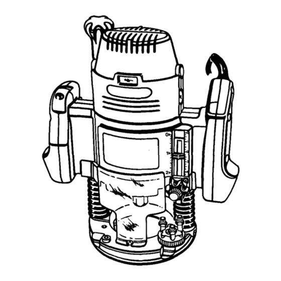
- Page 7 FEATURES REAR VIEW OF ROUTER DEPTH CONTROLKNOB POWER CORD LOCK HANDLE LOCK-ON BUTTON ON-OFF TRIGGER SWITCH HANDLE 5116-16 UNC-2B PLUNGE LOCK ACTUATOR HEX NUT ROUTER BASE STOP FLANGE SUBBASE COLLETNUT Fig. 2 ELECTRICAL CONNECTION Your router has a precision built electric motor. It should be connected to a power supply that is 120 volts, 60 Hz, AC only (normal household current).
- Page 8 " ADJUSTMENTS WARNING: Your router should never be connected to power supply when you are assembling parts, making adjustments, installing or removing cutters, or when not in use. Disconnecting you r router will prevent accidental starting that could cause serious injury. INSTALLING/REMOVING CU'I-rERS See Figures 3, 4, and 5.
- Page 9 ADJUSTMENTS INSTALLING/REMOVING CUTTERS MOTORSHAFT 1/2IN, (Continued) If installing cutter for the first time, it can be installed once collet nut is loose. If changing cutters, cutter will easily slip from collet after loosening collet nut. The 1/2 in. collet is machined to precision tolerances to fit cutters with 1/2 in.
- Page 10 ADJUSTMENTS ADJUSTMENTS DEPTH OF CUT See Figures 6, 7 and 8. When routinga groove that istoo deep tosafely cut in one pass, it isbest to make the cut in several passes. We recommend that several passes be made to reach deeper cuts. Proper depth of cutdepends on several factors: power of router motor,type of cutter being used, and type ofwood being routed.
- Page 11 ADJUSTMENTS DEPTH CONTROL KNOB See Figure 9. Fine adjustments can be made to the depth of cut by use of the depth control knob. Another primary use of the depth control knob is setting depth of cut when muter is mounted upside down on a muter table.
- Page 12 ADJUSTMENTS DEPTH STOP SYSTEM (Continued) Raise cutter by depressing plunge release actuator. Place router on flat surface, and lower router until tip of cutter barely touches flat surface. Squeeze plunge lock actuator to lock cutter at "zero" depth of cut. Turn adjustment knob counterclockwise to lower stop...
- Page 13 OPERATION WARNING: Always wear safety goggles or safety glasses with side shields when using your router. Failure to do so could result in dust, shavings, chips, loose particles, or foreign objects being thrown in your eyes causing possible sedous injury. If operation isdusty, also wear a face or dust mask. LOCK-ON BU'I'I"ON See Figure 13.
- Page 14 OPERATION PROPER FEEDING The right feed is neither too fast nor too slow. It is the rate at which the bit is being advanced firmly and surely to produce a continuous spiral of uniform chips -- without hogging into the wood to make large individual chips or, on the other hand, to create only sawdust.
- Page 15 OPERATION DEPTH OF CUT As previously mentioned, the depth of cut is important be- cause it affects the rate of feed which, in fLu'n, affects the DEPTH quality of a cut (and, also, the possibility of damage to your bit). A deep cut requires a slower feed than a shallow one, and OF _UT a too deep cut will cause you to slow the feed so much that the bit is no longer cutting, it is scraping, instead.
- Page 16 OPERATION EDGE ROUTING Place router on workpiece, making sure the router bit does ROUTER not contact workpiece. Turn router on and let motor build to its full speed. Begin your cut, gradually feeding cutter into workpiece. WARNING: TOP EDGE SHAPING Upon completion of cut, turn'motor off and let it come to e complete stop before removing router from work surface.
- Page 17 OPERATION ROUTING GROOVES See Figure 22. When muting across the face of boards, set muter at desired depth of cut, place the edge of router base against workpiece, and turn on your router. Slowly feed the cutter into the workpiece along desired cutline. WARNING: When routing straight cuts across stock, clamp a straight- edge to the workpiece...
- Page 18 OPERATION ROUTING WITH OPTIONAL ROLLER GUIDE See Figures 26 and 27. An optional roller guide is available for use with your router. It is useful for routing uneven edges and trimming laminates. The roller guide attaches to the guide holder as shown in figure 26.
- Page 19 OPERATION ROUTING WITH OPTIONAL GUIDE BUSHINGS (Cont'd) Secure template to the workpiece. Set router to desired depth ROUTER BASE of cut and turn it on. Place router base on the template with the collar of the guide bushing against the edge of the template.
- Page 20 , WARNING: found that they are subject to accelerated wear and possible premature failure, as the fiberglass chips and grindings are When servicing use only identical Craftsman replacement highly abrasive to bearings, brushes, commutators, etc.
- Page 21 MAINTENANCE PROPER CARE OF CUTTERS PROPER CARE OF COLLET Get faster more accurate cutting results by keeping cutters From time to time, it also becomes necessary to clean your clean and sharp. Remove all accumulated pitch and gum from collet and collet nut. To do so, simply remove collet nut from cutters after each use.
- Page 22 MAINTENANCE PLUNGE LOCK ACTUATOR ADJUSTMENTS COMPRESSION See Figure 32. The plunge lock actuator has been properly set at the factory and no initial adjustments should be required. However, after extended use slight readjustment may be required. If this situation occurs, make adjustments as PLUNGE follows: RELEASE...
- Page 23 MAINTENANCE DEPTH CONTROL KNOB ADJUSTMENTS See Figure34. The depth control knob is spring loaded against hex nut to prevent router motor from accidentally separating from router base. If depth control knob is tumed too far up depth adjustment rod, the spring will cause depth control knob to pop off before hex nut.
- Page 24 If mounting your router to a router table, use only the three 5/16-18 UNC-2B tapped holes provided in the router base. The use of Craftsman reuters in router tables offered Use 8/16-18 UNC-2A flat head screws that are 1-1/8 in. or 1-...
- Page 25 NOTES Page 25...
- Page 26 CRAFTSMAN ROUTER - MODEL NUMBER 315.275100 SEENOTE"A" NOTE: "A"- The assembly shown represents an important part of the Double Insulated System. To avoid the possibility of alteration or damage to the system, service should be performed by your nearest Sears Repair Center.
- Page 27 CRAFTSMAN ROUTER - MODEL NUMBER 315,275100 l The model number will be found on a plate attached to the motor housing. Always mention the model number in all correspondence regarding your I ..ROUTER or when ordering repair pads. PARTS LIST...
- Page 28 For repair of major brand appliances in your own home... no matter who made it, no matter who sold it! 1-800-4-MY-HOME Anytime, day or night , (1-800-469-4663) www.sears.com To bring in products such as vacuums, lawn equipment and electronics for repair, call for the location of your nearest Seers Parts & Repair Center 1-800-488-1222 Anytime, day or night www.sears.com...