Advertisement
Available languages
Available languages
Quick Links
truction
anu
®
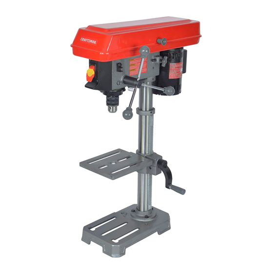
1/3 Horsepower
(continuous
duty)
2/3 Horsepower
(maximum
devemoped)
5-Speed, Step Pulley
620 - 3100 R.P.M. Drill Speed Range
1
P
FOR YOUR OWN SAFETY;
Read
and foUlow all of the Safety and
Operating
Instructions
before
Operating
this DdH Press.
Customer Helpline
1-800-897-7709
PRease have your Model No.
and SedaR No. availabUe.
Sears, Roebuck
and Co., Hoffman
Estates,
JL 60179 U.S.A.
Part No. OR93515
EspaSoL pg, 31
Advertisement

Related Manuals for Craftsman 152.219110


Summary of Contents for Craftsman 152.219110
- Page 1 truction ® 1/3 Horsepower (continuous duty) 2/3 Horsepower (maximum devemoped) 5-Speed, Step Pulley 620 - 3100 R.P.M. Drill Speed Range FOR YOUR OWN SAFETY; Read and foUlow all of the Safety and Operating Instructions before Operating this DdH Press. Customer Helpline 1-800-897-7709 PRease have your Model No.
- Page 2 Back Page ONE-YEAR FULL WARRANTY ON CRAFTSMAN TOOL if this Craftsman tool fails due to a defect in material or workmanship within one year from the date of purchase, CALL 1-800-4-MYoHOME _) TO ARRANGE FOR FREE REPAIR, if this tool is used for commercial or rental purposes, this warranty will apply for only ninety days from the date of...
- Page 3 12°in. Bench Drill Press with Laser°Trac Motor Specifications: Depth Stop Quick Set Motor type induction Depth Stop Type Continuous duty HP Depth Scab Column Diameter 2o3/8" Maximum developed HP 2/3 Base Work Area 8ol/2" wide x 9o3/8" depth Amps Volts 6"...
- Page 4 GENERAL SAFETY iNSTRUCTiONS AVOID ACCIDENTAL STARTING, Make sure that the power switch is in the "OFF" position before Operating a drill press can be dangerous if safety and plugging in the power cord to the electrical common sense are ignored, The operator must be receptacle, familiar with the operation of the tool, Read this manual to understand this drill press, DO NOT operate this drill...
- Page 5 GUIDELINES FOR EXTENSION CORDS 20. MAINTAIN TOOLS WITH CARE. Always keep tools clean and in good working order. Keep all blades and tool bits sharp. The smaller the gauge number, the larger diameter of the extension cord is. if in doubt of the proper size of an 21.
- Page 6 THIS TOOL MUST BE GROUNDED while in use to The motor supplied with your drill press is a 120 volt, protect the operator from eUectric shock. singb-phase motor. Never connect the green wire to a live terminal. IN THE EVENT OF A MALFUNCTION OR BREAK- USE ONLY A 3-WIRE EXTENSION CORD THAT HAS DOWN, grounding provides the path of bast resistance...
- Page 7 SPECIFIC SAFETY iNSTRUCTiONS 13, NEVER PERFORM LAYOUT, ASSEMBLY SETUP WORK on the table/work area when the The operation of any drill press can result in debris drill press is running, being thrown into your eyes, which can result in severe 14, NEVER START THE DRILL PRESS BEFORE eye damage, ALWAYS WEAR EYE PROTECTHON, Any CLEANING THE TABLE OF ALL OBJECTS (tools,...
- Page 8 Sears may recommend other accessories not listed in this manual Visit your Sears Hardware Department or see the Craftsman Power and Hand Tool Catalog for the follow- See your nearest Sears Hardware Department or ing accessories, Craftsman Power and Hand Tool Catalog for other...
- Page 9 Figure 1, Beit cover 11, Base 6, Laser (not shown) 2, Motor 12, Flexible lamp 7, Keyiess chuck 3, Beit tension Hockknob 8, Column 13, Adjustable depth stop 4, Feed handies 9, TaMe raise/iower Handie 14, ON/OFF switch 5, QuHH Hock 10, TaMe...
- Page 10 Figure 15, ON/OFF switch 16, Removable key 17, Depth scale lock nuts 18, Depth scale Figure 19, Bevel scale 20, Table lock handle...
- Page 11 UNPACKING AND CHECKING CONTENTS Compare the items to Figure 3-1 below; verify that all items are accounted for before discarding the shipping This drill press will require some amount of assembly, box, If there are any missing parts, call Customer Remove all of the parts from the shipping box and lay Helpline 1°800°897°7709, them on a clean work surface,...
- Page 12 TOOLS REQUIF{EB Figure The following toob are needed for assembly and align- ment, Note: Two hex wrenches (3mm and 4mm) are provided, The remaining tools are typbal shop toob and are not included with your drill press, 12ram Open end wrench Hammer and block of wood 13ram Open end wrench Combination square...
- Page 13 NOTE: P lacethe rackunder the bottom ofthe ring,but allowenough clearance s o thattherackcanrotate around thecolumn, T ighten thesetscrew(R), See Figure4-7, Figure SNde the rack (F) and the tabb (M) onto the column (A), See Figure 4-5, Figure Attach the tame raising and bwedng handb (S) on the worm gear shaft (I) and tighten the set screw (T) against the flat (U) on the worm gear shaft, See...
- Page 14 DRILL PRESS HEAD AND Figure MOTOR ASSEMBLY * The drHU press is a heavy machine; two peopb may be required for certain assemMy operations, * MAKE CERTAIN the drHU press is disconnected from the power source, Figure Thread the three feed handbs (F) in the three tapped hobs (G) bcated in the pinion shaft (H), Figure Seat the drHU press head (A) on the coUumn (B),...
- Page 15 Figure Figure 6°2 Open the chuck jaws compbteUy, hoUdthe top collar Remove battery cover (C) from ]aser housing, (K) and turn the chuck barreU(L) counter-clockwise, Make sure the jaws are compbteUy recessed inside Connect a 9-voUt battery (D) (not incUuded) to the chuck, See figure 5-5, battery termina] (E), Seat the chuck onto the drHU press spindb as far as...
- Page 16 FASTENING DRILL PRESS Figure The drill press should be fastened to a supporting surface, Secure the machine base to the supporting surface with an M8x1,25x125mm carriage head screw, 8,5ram fiat washer, 8,Smm lock washer, and M8x1,25 hex nut through the two hobs (A) located in the machine base, See Figure 7:1, This win help reduce the tendency of the drill press to tip over, slide, or walk,...
- Page 17 FLEXIBLE LAMP * DONOTexpose theddH pressto rainoroperate the in dampbcations. To reduce the risk of fire, use 40 watt or bss, 120 voUt, reflector track-type Hght buUb(not supplied). DO NOT * MAKESUREaHpartshavebeen assembbd correctly use a standard househoUd Hght buUb. The reflector track- andarein working order.
- Page 18 Figure 10-2 Figure 10-4 Turn the table raising and lowering handle (D) clockwise to raise the table and counterclockwise Loosen the table locking bolt (G) and tilt the table to to lower the table, See Figure 10-2, the desired angle, and tighten the table locking bolt, See Figure 10-4, 3, After the table is at the desired height, tighten the table clamp,...
- Page 19 DRULL SPEEDS MAKE CERTAIN the drill press is disconnected from the power source, Five drill speeds (620, 1100, 1720, 2340, and 3100 RPM) are available with your drill press, See Figure 11-1 to select the correct spindle speed for your operation, This diagram can also be found on the inside of the belt cover of the drill press, Figure...
- Page 20 DRULLING HOLES TO DEPTH ADJUSTING RETURN SPRUNG The ddH chuck wHU automatically return sUowUy to its upper position when the handUe is reUeased, The return MAKE CERTAIN the drill press is disconnected from spring was propedy adjusted at the factory, However, to the power source.
- Page 21 LASER ADJUSTMENTS Figure 15-3 MAKE CERTAIN the drill press is disconnected from the power source, • LASER LIGHT - DO NOT STARE INTO BEAM, APERTURE, or into a reflection from a mirror-like surface, Figure 15-1 Loosen the two screws (U)on the face (J) of the left side laser, See Figure 15-3, On the alignment pin (A) there is a vertical line scribe (L) into it, This is used to set parallelism of...
- Page 22 Figure 15-5 iNSTALLiNG AND REMOVING DRILL BiTS MAKE CERTAIN the drill press is disconnected from the power source, Figure 16-1 ii' i ' ..11, Adjust the drHU press tame so that it is about 1" under the alignment pin, Hold the collar (A) and turn the chuck barrel (B) 12, Lay a 3/4"...
- Page 23 SUPPORTING WORKPIECE QUILL LOCK The quill allows the up and down movement of the chuck, Different setup or working operation may USE only recommended accessories, require the quill to be lower and locked into position, Figure 17-1 Figure 18-1 IMPORTANT: When the workpiece (A) is long enough, position it on the table with one end against the left side of the column (B) to prevent the workpiece from rotat- ing, See Figure 17ol,...
- Page 24 CORRECT DRiLLiNG SPEEDS DRULUNG METAL, ALUMINUM OR BRASS Factors that determine the correct speed are: the work- piece, the size of the hoUe,the type of bit or other cutter, and the quality of cut wanted, NEVER hold the workpiece in your bare hands. ALWAYS use clamps or vises to hold your workpiece.
- Page 25 CHANGmNG LASER BATTERY Turn the power switch OFF and unplug the power Turn the power switch OFF and unplug the power cord cord from its power source, from its power source, LASER UGHT - DO NOT STARE mNTOBEAM, The drill press has sealed lubricated bearings in the APERTURE, or into a reflection from a mirror-like surface,...
- Page 26 TOPREVENT I NJURY TOYOURSELF o r damage to theddH press, t urntheswitchtotheOFFposition andunpUug thepower cordfromtheeUectrbaU receptacle b efore making anyadjustments, PROBLEM SOLUTION UKELY CAUSE(S) Motor does 1. Switch key is removed. 1. insert switch key. not start or 2. Defective switch. 2.
- Page 27 12qn.BenchDrill Press MODEL N0.152.219110 Whenservicing, useonUy C RAFTSMAN r epUacement parts,Useof anyotherpartsmaycreatea HAZARD or cause product d amage, Anyattempt t o repair o r repUace eUectricaU partsonthis drHU p ressmaycreatea HAZARD unUess a qualified service technician d oesrepairs, R epair s erviceis avaHaMe atyournearest S earsService Center, AUways orderby PART NUMBER, notbykeynumber, PART PART...
- Page 28 12-in.BenchDrill Press MODEL N0.152.219110 PART PART DESCRiPTiON QTY= DESCRiPTiON QTY= 0R92695 0R92725 M8x125mm Hex Hd Screw Motor Jumper 0R92696 Power Cord 0R90290 3ram Hex Wrench 0R92697 0R90291 4ram Hex Wrench Ring 0R90222 M6xlOmm Hex Soc Set Screw 0R90289 2.5ram Hex Wrench 0R92702 Worm 0R92707...
- Page 29 12-in.BenchDrill Press MODEL N0.152.219110 /o/!8 /" 2B (3 (2)_ (2)/...
- Page 31 ® 1/3 CabaHos de Fuerza (servicio continuo) 2/3 CabaHos de Fuerza (m_ximo desarroHado) 5 Velocidades, Polea Escamonada Gama de Velocidades de PerforaciSn 620o3100 R.P.M. No. de Mode_o 152.219110 PARA SU SEGURJDAD PERSONAL, Reay obedezca todas Uas lnstrucciones Seguddad y Operaci6n antes de operar esta Taladradora de Banco...
- Page 32 GARANTiA COMPLETA DE UN ANO PARA LAS HERRAMIENTAS CRAFTSMAN Siesta herramienta Craftsman Ibgase a failar debido a defectos materiabs o de elaboraci6n dentro de un aho a partir de la fecha de compra, LLAME AL 1-800-4-MY*HQME @ (en EE,UU,) PARA CQQRDINAR...
- Page 33 Taladradora de Banco de 12 pu_g° con LaseroTrac Inclinaci6n de Mesa Movimiento de Mesa Cremallera y pi_6n _ecificaciones deI Motor: Material de Mesa Hierro moldeado Tipo de Motor Inducci6n HP Servicio Continuo Tope de Profundidad HP Maximo Desarrollado Quick-Set Tipo de Tope de Profundidad Ampefios Escala de Profundidad Voltios...
- Page 34 INSTRUCCIONES GENERALES EVITE LOS ARRANQUES ACCIDENTALES. Aseg0rese de que el interrupter de energ[a se encuentre en la posi- DE SEGURIDAD ci6n de "OFF" (apagado) antes de enchufar el cord6n de El uso de una taIadradora puede ser peligroso si se hace potencia y causar dare a la herramienta.
- Page 35 21. NUNCA D EJE UNA M_,QU_NA ENFUNCJONAM_ENTO DIRECTRJCES PARA LAS SiNATENDER A pague e linterrupter deenerg[a a Ia EXTENSUONES ELECTRICAS posici6n de"OFF" (apagado). NOsealeje deJamb, quina hasta que sehaya detenido percompbto. Mientras menor sea el n0mero de calibre, mayor sera el diametro de la extensi6n electrica.
- Page 36 USE SOLO UNA EXTENSKSN EL¢:CTRICA DE TRES HJLOS ESTA HERRAMIENTA DEBE ESTAR CONECTADA CON ENCHUFE DE CONEXJ6N A TIERRA DE TRES TJERRA durante el uso para proteger al operario contra los MACNOS Y UN RECEPTACULO DE TRES MACNOS QUE choques eI6ctficos. ACEPTE EL ENCNUFE DE LA NERRAMJENTA.
- Page 37 INSTRUCCIONES ESPEC[FICAS 13. JAM.&S REAUCE LABORES DE TRAZADO, ENSAM- BLADO O MONTAJE sobre Ia mesa / zona de traba]o DE SEGURJDAD cuando la maquina este funcionando. El uso de cuatquier taladradora puede expulsar escombros 14. JAM,&S ARRANQUE LA TALADRADORA SiN ANTES hacia los ojos durante Ias operaciones, Io que puede causar HABER DESPEJADO...
- Page 38 Visite su Departamento de Ferreteffa Sears o consulte el CatAIogo de Herramientas Manuales y Mecanicas de Consulte con su Departamento de Ferreter[a Sears mas cer- Craftsman para los siguientes accesorios: cane o su Catalogo de Herramientas Manuales y Mecanicas de Craftsman para otros accesofios.
- Page 39 Figura Cubierta de la correa 11. Base Lb,ser (no ilustrado) Motor Mandrino sin Ilave 12. Lampara flexible Perilla de cierre de tensi6n de Columna 13. Tope de profundidad ajustable correa Agarradera de izado / bajado de 14. Interruptor ENCENDIDA / APAGADO Agarraderas de alimentaci6n mesa Cierre de arbol hueco...
- Page 40 Figura 15, Interruptor de ENCENDIDO / APAGADO 16, Llave Desmontable 17, Tuercas de cierre de la escala de profundidad 18, Escala de profundidad Figura 19, Escala de biselado 20, Agarradera de cierre de mesa...
- Page 41 DESEMPAQUE Y COTEJO Asegurese de frotar la cera para eliminada antes dei montaje. DEL CONTENIDO Compare los art[culos con la Figura 3-1 abajo y compruebe que todos los art[culos esten contabilizados antes de descar- Esta taIadradora necesitara cierta cantidad de montaje. Quite tar Ia caja de envio.
- Page 42 HERRAMIENTAS REQUERIDAS Figura Se requieren Ias siguientes herramientas para el montaje y aIineaci6n= Aviso: Se proporcJonan dos Ilaves hexagonales (3 mm y 4 mm). Las herramientas restantes son herramientas t[picas de taller que no estg,n incluidas con su taJadradora= LIave de boca de 12 mm Martillo y bloque de madera LIave de boca de 13 mm Escuadra de combinaciones...
- Page 43 AVJSO: Coloque Ia cremallora debajo del fondo dol anillo, Figura pero permita que exista suficionte espacio libre para quo la cremallora pueda girar on torno a Ia columna. Apriote el tornillo do fijaci6n (R). Ver la Figura 4-7. Figura Doslice la cromallera (F) y la mesa (M) sobre la columna (A).
- Page 44 MONTAJE DEL CABEZAL Y MOTOR Figura DE LA TALADRADORA La taladradora es una maquina pesada. Podrgn requerirse dos personas para desembalar y Ievantar Ia maquina. o ASEGURESE de que la taladradora este desconectada Jafuente de energfa. Figura Enrosque Ias tres agarraderas de alimentaci6n (F) en Ios tres agujeros roscados (G) Iocalizados en el eje deJ piB6n (H).
- Page 45 Figura Figura Abra Ias mand[buIas del mandrino compIetamente. Quite Ia cubierta de Jabateffa (C) deJ alojamiento deJ Suiete eI collar[n superior (K) y gire el barril del mandrino laser. (L) en sentido antihorario. Aseg0rese de que Ias mand[buIas esten compIetamente recesadas dentro del Conecte una bater[a de 9-voltios (D) (no incluida) a Ias mandrino.
- Page 46 AFIANZANDO LA TALADRADORA Figura La taladradora debe afianzarse a una superficie de apoyo, Afiance la base de Ia maquina a la superficie de apoyo con un tomilIo de carrocerfa M8 x 1,25 x 125 ram, arandela plana de 8,5 mm, arandela de cierre de 8,5 mm y tuerca hexagonal M8 x 1,25 a traves de los dos agujeros (A) Iocalizados en la base de la maquina, Vet la Figura 7-1, Esto ayudarb_ a reducir la tendencia de la taladradora a volcarse, deslizarse o...
- Page 47 LAMPARA FLEXIBLE o NO exponga la taladradora a la IIuvia ni tampoco la opere en lugares h0medos. Para reducir eJ peligro de incendios, utilice una bombiIla de ASEGORESE de que todas Ias piezas hayan side correcta- 40 vatios o menos, 120 voltios tipo reflector (no suministrado). mente montadas y que esten en buen estado de funciona- NO UTJLJOE una bombilb domestica estandar.
- Page 48 Figura 10-2 Figura 10-4 Gire Ia agarradera de izado y bajada de mesa (D) en sentido horario para eIevar Ia mesa yen sentido anti- Afioje eI pemo de cierre de Ia mesa (G) e incline la mesa horario para bajada. Ver la Figura 10-2. al anguIo deseado.
- Page 49 VELOCIDADES DEL TALADRO ASEGURESE de que la taladradora este desconectada de Ia fuente de energfa. Hay cinco velocidades de taladrado (620, 1100, 1720, 2340 y 3100 RPM) disponibIes con su taladradora. Vet la Figura 11-1 para seIeccionar la velocidad de huso correcta para su operaci6n. Este diagrama tambien podrb, hallarse dentro de la cubierta de la correa de la taIadradora.
- Page 50 PEFtFORANDO AGUJEROS AJUSTANDO EL RESORTE DE RETORNO PROFUNDIDAD EI manddno de la taladradora regresara lentamente y de forma automatica a su posici6n superior al soltar Ia agarra- dera. EI resorte de retomo fue ajustado correctamente en Ia fb, b rica. Sin embargo, si resulta necesario efectuar ajustes: ASEGURESE de que la taladradora este desconectada...
- Page 51 AJUSTES OEL LASER Figura 15-3 ASEGURESE de que Jataladradora este desconectada Jafuente de energ[a, o LUZ LASER - NO MIRE EL HAZ, LA APERTURA n[ tam- poco eJ reflejo de una superficie espejada, Figura 15-1 Afloje los dos tornillos (H)sobre Ia cara (J) del I_ser en el lado [zquirrdo, Ver Ia Figura 15-3, En el pasador de alineaci6n (A) existe una I[nea vertical de trazado (L), Esto se utiIiza para estabIecer el parale-...
- Page 52 INSTALACION Y DESMONTAJE Figura 15-5 DE BROCAS ASEGURESE de que la taladradora este desconectada de la fuente de energia, Figura 16-1 i! ¸ 11, Ajuste la mesa de la taladradora de manera que quede a aproximadamente 1 pulgada bajo el pasador de aHneaci6n, Sujete el collarin (A) y gire el barril del mandrino (B) en sentido antihorario para eerrar las mandi-...
- Page 53 APOYANDO EL MATERIAL ENCLAVAMIENTO DEL .4,RBOL HUECO El arbol hueco permite el movimiento deI mandrino hacia arriba y abajo. Las configuraciones de montaje o las opera- ciones de trabajo distintas podrb,n exigir que el b, r bol hueco SOLO utilice accesorios recomendados. este mas bajo y enclavado en su sitio.
- Page 54 VELOCIDADES DE PERFORACION PERFORACION DE METALES, APROPIADAS ALUMINIO O BRONCE Los factores que determinan Ia mqor velocidad a ser utiIizada en cualquier funci6n de taladrado son: eI tipo de material a ser elaborado, el tamaflo del agujero, tipo de broca u otra NUNCA suiete el material con Ias manes descubiertas.
- Page 55 CAMB[ANDO LA BATERiA DEL LASER LUBRICAC[6N APAGUE el interruptor y desenchufe el cord6n de energfa APAGUE el interruptor y desenchufe el cord6n de energia de de su fuente de suministro. la fuente de sumin[stro. o LUZ LASER - NO MIRE EL HAZ, LA APERTURA ni tam- La taladradora tiene cojinetes lubricados se[Iados en el...
- Page 56 PARA EVSTAR HERIRSE A Si rWlSMO o causar daf_o a la taladradora, conmute el interruptor a la posici6n de apagado (OFF) y desenchufe el cord6n de energ[a del tomacorrientes antes de realizar cuaIquier ajuste= PROBLEMA CAUSA(S} POSIBLES SOLUCJ6N Motor 130 arranca 1.
- Page 57 Taladradora de Banco de 12 Pumg, NO. DE MODELO 152,219110 Cuando vaya a rendir servicio, s61o utilice piezas de recambio CRAFTSMAN. El uso de cuatquier otro tipo de piezas podrb, crear un PEUGRO o producir dahe al producto. Cualquier intento per reparar o reemplazar Ias plazas etectricas de esta taladradora podrb_crear un PELIGRO a menos qua la reparaci6n sea efectuada por un tecnico de servicio competente.
- Page 58 Tatadradora de Banco de 12 Pumg, NO. DE MODELO 152,219110 No de No. de No de No, de C_ave £iezas Cant. Clave Piezas Descripci6n Descripci6n Cant. OR92695 Barrenador de1 motor OR92725 Tornillo cab, hex, M8 x 125 mm OR90290 Llave hex_ 3 mm OR92696 Cordon de energfa OR92697...
- Page 59 Tatadradora de 8anco de 12 Pum9, NO. DE MODELO 152,219110 (2)_ I[05...
- Page 60 Your Home For repair-in your home-of all major brand appliances, lawn and garden equipment, or heating and cooling systems, no matter who made it, no matter who sold it! For,the replacement parts, accessories owner s manuals that you need to do-it-yourself. For Sears professional installation of home appliances and items like garage door openers...