Table of Contents
Advertisement
Available languages
Available languages
Advertisement
Table of Contents

Related Manuals for Craftsman 196.205690


Summary of Contents for Craftsman 196.205690
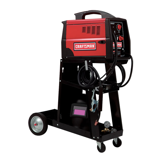
- Page 1 Owner's Manual JCRAFTSMAN" I WIRE FEED MIG WELDER Model No. 196.205690 CAUTION: Before using this product, read this manual and EspaSol p.31 follow all its Safety Rules and Operating Instructions. Sears, Roebuck and Co., Hoffman Estates, IL 60179 U.S.A. www.sears.com/craftsman...
- Page 2 Install the Shielding Gas ....12 Suggested Settings ......Limited Three-Year Warranty on Craftsman Welder For three years from the date of purchase, if any part of this welder, except for the gun or cables, fails due to a defect in material or workmanship, return it to your nearest Sears Parts &...
-
Page 3: Important Safety Information
Note: • The following safety alert symbols identify Every craftsman respects the tools with important safety messages in this manual. which they work. They know that the tools • When you see one of the symbols shown represent years of constantly... -
Page 4: Flash Hazards
SHOCK HAZARD into the power source if the ground prong on power cord plug is bent over, broken off, or missing. • Do not allow the welder to be connected WARNING to the power source or attempt to weld if the welder, welding cables, welding site,... -
Page 5: Fire Hazards
helmet and replace any cracked or • Do not wear gloves or other clothing that broken filter lenses IMMEDIATELY. contains oil, grease, or other Do not allow the uninsulated portion flammable substances. of the wire feed gun to touch the ground •... -
Page 6: Fume Hazards
chlorinated hydrocarbons, such as to prevent spatter or slag from falling into ear. trichloroethylene and perchloroethylene, can be decomposed by the heat of an Make sure welding area has a good, electric arc or its ultraviolet radiation. solid, safe floor, preferably concrete These actions can cause PHOSGENE, a masonry,... -
Page 7: Additional Information
temperatures above 130°F ADDITIONAL SAFETY will require water spray cooling. INFORMATION • Do not expose cylinders to electricity For additional information concerning any kind. welding safety, refer to the following Do not use a cylinder or its contents standards and comply with them as anything other than its intended use. -
Page 8: Welder Operating Characteristics
DESCRIPTION can weld for four (4) minutes out of 10 with Your new MIG (Metal Inert Gas) wire feed the remaining six (6) minutes required for cooling. (See Table 2). welder is designed for maintenance sheet metal fabrication. The welder consists Table 2. - Page 9 Power Switch - This switch turns the welder ON and OFF. (Make sure the power switch is Handle in the OFF position before performing any maintenance on the welder.) Wire Speed Gun Cable Power Cord - This is a standard, grounded Voltage 120 volt power cord.
-
Page 10: Power Source Connection
Select a properly grounded extension cord that will mate directly with the power source POWER SOURCE CONNECTION receptacle and the welder power cord without the use of adapters. Make certain that the POWER REQUIREMENTS extension is properly wired and in good electrical condition. -
Page 11: Installing The Handle
shield handle. (DO NoT DISCARDT) tighten both screws. Place the shaded lens into the space Align the holes of the back foot with the provided on the inside of the face shield. rear screw holes on the bottom of the welder. -
Page 12: Check The Gas Flow
CHECK THE GAS FLOW Gas Selection For Stainless Steel Welding The best shielding gas for stainless steel welding is a mixture of 90% Helium, 7.5% WARNING Argon, and 2.5% Carbon Dioxide. However, 100% Argon can also be used, but an increase in the area being heated by the arc IMPROPER HANDLING AND MAINTENANCE... -
Page 13: Align And Set The Drive Roller
-MAKE SURE TO TURN OFF THE GAS , Drive CYLINDER VALVE WHEN DONE Roller WELDING. ALIGN AND SET THE DRIVE ROLLER Before installing any welding wire into the unit, the proper sized groove must be placed into position on the wire drive mechanism. Change the drive roller according to the fol-... - Page 14 Note: If TOO MUCH tension is applied to the wire spool, the wire will slip on the drive roller or will not be able to feed at all. If TOO LITTLE tension is applied, the spool of wire will want to unspool itself.
-
Page 15: Change Polarity
job. The VOLTAGE selector controls the CHANGE POLARITY weld heat. There are four voltage heat This welder allows you the capability to selections (lettered A through D) available change the welding current polarity. You may on this welder. Position A provides select either dc Straight (dc - Flux Cored) or lowest voltage (heat) and position... -
Page 16: Controls And Indicators
allowing the metals to flow together through the use of an electrical arc. The electrical is created between a continuous consumable Operation of this welder consists of selecting and adjusting operating controls for optimum wire electrode (the welding wire) and the voltage (welding heat) and wire speed settings. -
Page 17: Welding Techniques
degrees. The point at which the gun Distance from the Work Piece handle is parallel to the work piece. If The end of the welding gun is designed with angle A is increased, penetration will the contact tip recessed from the end of the increase. -
Page 18: Types Of Weld Beads
relation to the weld puddle. The gun is either centered over the weld joint. This is the easi- est type of bead to make. PUSHED (see Figure 11) into the weld pud- dle or PULLED away from the weld puddle. PUSH Puddle PULL... -
Page 19: Multiple Pass Welding
angle B (see HOLDING THE GUN - p.16) is such that the wire, and therefore the arc force, is directed more toward the metal above the ]WARNING weld joint. This is to help prevent the weld puddle from running downward while still allowing slow enough travel speed to achieve Hot slag can cause fires and serious injury... -
Page 20: Spot Welding
NOTE: WHEN USING SELF-SHIELDING of a continuous weld bead. There are three FLUX-CORE WIRE it is very important methods of spot welding: Burn-Through, thoroughly chip and brush the slag off each Punch and Fill, and Lap (see Figure 20). completed weld bead before making another Each has advantages and disadvantages... -
Page 21: Maintenance
Select the wire diameter, heat setting, and tune in the wire speed as if you were welding the same thickness material with This welder has been engineered to give a continuous bead. many years of trouble-free service providing that a few very simple steps are taken to 3. -
Page 22: Maintaining The Nozzle
Always use a contact tip stamped with the A SHORTED nozzle results when spatter same diameter as the wire it will be used buildup bridges the insulation in the nozzle, with. allowing welding current to flow through it as Note: Due to inherent variances in flux-cored... -
Page 23: Troubleshooting
Take gun handle halves apart by remov- Nozzle ing five phillips head screws. Remove liner from fast coupler fitting on gas valve. Depress lip on fast coupler Contact Tip back towards fitting and pull liner out. Remove liner from outer torch sleeve and Gas Diffuser pull out. - Page 24 POSSIBLE REMEDY POSSIBLE CAUSE TROUBLE 1. Plugged welding nozzle 1, Clean or replace nozzle. Dirty, porous, brittle weld 2. No shielding gas 2. Tank empty, flow restricted or regulator set too low. 3. See SELECTING SHIELD- 3. Wrong type of gas ING gas section of manual•...
- Page 25 _L,_' pT( .f, p T $3_- / ' PT( (PT 6AS/NO GASCHANGE eJ114 r--T-_ E__,F<..-' _ (< 120V '$1[ 60Hz [_-L.__. L._J +® I'_ _''" "_1 I+<_----------',_ "1 I -<_-----_:::::_ (..£____.J E 0592 22710044...
-
Page 26: Suggested Settings
Code Description Qty. WE20569-21690175 Front Plastic Frame WE20569-21690176 Back Plastic Frame WE20569-21600021 Plastic Hanlde WE20569-21610014 Front Plastic Foot WE20569-21610015 Back Plastic Foot WE20569-05000065 Front Panel Lower Panel WE20569-33700138 WE20569-33715063 Rear Panel WE20569-33720063 Dividing Panel WE20569-05000066 Right Upper Panel WE20569-05000067 Access Door WE20569-22200035 Yellow Power Switch 16A-250V WE20569-22205117... - Page 27 WIRE FEED WELDER MODEL 196.205690 PARTS DIAGRAM 4 42 65 j...
- Page 28 ,,=, ,,=,...
- Page 29 No. Code Description Qty. WE20569-21690300 Black Gun Handle WE20569-21690301 Red Trigger for Gun WE20569-23005009 Gun Gas Valve WE20569-23005145 Gun Neck WE20569-23005091 Thread Guide Wire Liner Conductor Tube Insulation WE20569-23005090 WE20569-23005146 Gas Diffuser 08a WE20569-23005018 .024 (0.6mm) Contact Tip `= 08b WE20569-23005019 .030 (0.8mm) Contact Tip ] 08c WE20569-23005020...
- Page 30 SUGGESTED SETTINGS FOR WELDER I CRRFTSMRN°I Recommendations only -yariations in input power, welding position, wire, and gas will affect the weld characteristics: Use the voltage setting and wire speed indicated as a starting point then adjust for var!_M,_ such as stick out, travel _%pe__,__, .-_.--! d- =n_,_, _b_mnlin_ss of metal,...
-
Page 31: General
Graduaciones Sugeridas ....Garantia limitada de Tres Afios de la Soldadora Craftsman Si cualquier parte de 6sta soldadora, excepto por la pistola o los cables, fallase debido a un defecto de materiales o de fabricaci6n durante tres afios a partir de la fecha de compra, devolverla al Centro de Reparaciones y Repuestos de Sears mas cercano y Sears la reparara sin costo alguno. -
Page 32: Informacion Importante De Seguridad
Nota: Los siguientes s[mbolos de alerta de seguridad identifican mensajes de seguridad Todo artesano respeta las herramientas con las importantes en este manual. que trabaja. Sabe que las herramientas • Cuando vea uno de estos simbolos que representan afios de mejoras y desarrollo se indican a continuaci6n, este alerta a la constantes. -
Page 33: Riesgos De Choque Electrico
RIESGOS DE CHOQUE ELECTRICO • No intentar enchufar la soldadora a un tomacorriente si la clavija para conexi6n a tierra en el enchufe del cord6n estuviese doblado, roto o faltante. • No permitir que la soldadora se conecte a un tomacordente, ni intentar soldar si la iLAS DESCARGAS... - Page 34 los arcos de soldar producen chispas, gotean dejando una mancha negra permanente metal derretido y escoria caliente y pedazos de el campo de visi6n. Debe usarse una careta metal caliente que pueden iniciar incendios, con un lente oscuro No. 10 (minimo). quemar la piel y lesionar los ojos.
-
Page 35: Riesgos De Vapores
para uso inmediato! Se recomienda un extintor causar incomodidad, enfermedad o muerte. • No soldar ni cortar en areas donde existan port&til de quimico tipo ABC. solventes clorinados. Los vapores de los • Cuando se suelde en posiciones por encima hidrocarbones clorinados tales come el de la cabeza, usar tapones de oidos para tricloroetileno y percloroetileno, pueden... - Page 36 INFORMACION ADICIONAL necesitan rociarse con agua para que se enfrien. DE SEGURIDAD • No exponer los cilindros a tipo alguno de electricidad. Para informaci6n adicional referente a la • No usar los cilindros o su contenido seguridad para soldar, referirse alas siguientes para prop6sitos diferentes a los que Normas y cumpla con Io que sea aplicable.
- Page 37 La soldadora tiene un ciclo nominal de DESCRIPCI(_N trabajo de 40% con la salida especificada. Su nueva soldadora MIG (Gas Inerte al Metal) con Esto significa que se puede soldar por alimentador de alambre est& disehada para cuatro (4) minutos de cada ciclo de trabajos de mantenimiento y fabricaciones con funcionamiento de 10 minutos,...
- Page 38 Interruptor: Enciende (ON) y apaga (OFF). (Cerciorarse que el interruptor est6 en la posici6n de apagado (OFF) antes de realizar cualquier mantenimiento a la soldadora). Vel.de Alim.del alambre Cablede lapistola Cordbn de Suministro El_ctrico: Selector Es un cord6n est&ndar de 120 voltios con de voltaje conexi6n a tierra.
- Page 39 soldadora sin usar adaptadores. Cerciorarse que el cord6n de extensibn sea de los CONEXll _NAL SUMINISTRO alambres adecuados y que este en buenas ELECTRICO condiciones el6ctricas. Los cordones extensi6n deben tener alambres Cal. 12 REQUISITOS DE CORRIENTE como minimo y no deben exceder de 7,6m Esta soldadora est_ disefiada para operar con (25') de largo.
- Page 40 ENSAMBLAJE DE LA Ajustar ambos tomUlos firmemente un desarmador con punta en cruz. CARETA PARA SOLDAR Alinear los orificios de las patas posted- 1. Quitar la u_as retenedoras de la lente y ores con los orificios en la parte posterior la tuerca del mango del brazo de la inferior de la soldadora.
- Page 41 VERIFICACI(_N DEL FLUJO DE GAS de soldadura fundida paracuandose sueldaen superficies verticaleso elevadassuspendidas. Seleccion del Gas para Soldar Acero Inoxidable ADVERTENCIA El mejor gas auto protegidopara soldar acero inoxidable es una mezcla de 90% de helio con 7,5% de arg6n y 2,5% de di6xidode carbono. Sin iLA MANIPULACI(_N O EL MANTENIMIENTO embargo,tambien se puede usar 100% de arg6n;...
- Page 42 -RECUERDE CERRAR LA VALVULA R_'di_l°c_e DEL CILINDRO DE GAS CUANDO TERMINE DE SOLDAR. ALINEAMIENTO Y REGULACI()N RODILLO DE AVANCE Antes de instalarcualquieralambre soldadoren la unidad,debe colocarla ranura del tamafio adecuado en posici6nen el mecanismo de el Motor avance del alambre. Cambiar el rodillo de avance de acuerdo a los Figura 5.
- Page 43 Nota: Si se aplica DEMASIADA tensi6n al carrete, el alambre resbalar_ en el rodillo de avance o no podr& alimentarse. Si hay MUY POCA tensi6n, el carrete de alambre tender& a desenrollarse solo. Regular la tensi6n freno seg0n sea necesario para evitar estos problemas.
- Page 44 CAMBIO DE POLARIDAD voltaje (calor) recomiendan para su trabajo de soldadura. El selector de VOLT/ME controla el Esta soldadora permite carnbiar la poladdad de la calor para soldar. En esta soldadora hay ocho corriente de soldar. Se puede seleccionar CD ya selecciones de voltaje (calor) marcadas con sea de poladdad regular (CD - soldadura de las letras "A"...
-
Page 45: Controles E Indicadores
APRENDA A SOLDAR La soldadura MIG (Gas Inerte al Metal) es un La operaci6n de esta soldadora consiste en proceso para unir piezas metdlicas mediante el seleccionar las graduaciones 6ptimas para los calor generado por un arco el_ctricoque permite controles de voltaje (calor para soldar) y para fusionar los metales. - Page 46 cuando el mango de la pistola est_ pieza de trabajo Distancia a la paralela a la pieza de trabajo. Si el El extremo de la pistola soldadora est_ disefiado &ngulo A aumenta, la penetraciSn con una punta de contacto empotrada en la aumenta.
- Page 47 soldadura Empujando fundida Jalando Figura 11. Direcci6n de Desplazamiento Figure 12. Cord6n de refuerzo Para la mayoria de los trabajos de CORDON TEJIDO (Figura 13) se usa soldadura se jala la pistola a Io largo de cuando se quiere depositar metal sobre la._nta para ver mejor el charco de un espacio m&s amplio que el que seria soJ_adura fundida.
- Page 48 arco, se dirige m_ls hacia el metal encima de la junta. Esto ayuda a que el charco de soldadura no escurra hacia ADVERTENClA abajo y se desplace con suficiente lentitud para Iograr buena penetraci6n. Un buen punto de partida para el _ngulo La escoria puede producir incendios...
- Page 49 MI_TODOS ESPECIALES PARA SOLDAR Las ilustraciones de la Figura 18 muestran la secuencia para formar cordones de soldadura SOLDADURA DE PUNTOS de varias pasadas en una junta a tope El prop6sito es unir piezas de metal con puntos biselada. en vez de cordones de soldadura. Hay tres m6todos de soldadura de puntos: perforaci6n NOTA: AL USAR ALAMBRE FUNDENTE...
-
Page 50: Mantenimiento
2. El MI_TODO DE PERFORACION MECANICA Y RELLENO produce la soldadura de mejor acabado de estos MANTENIMIENTO GENERAL tres m6todos. En este m6todo se hace Esta soldadora estd disefiada para ofrecer un agujero con un troquel o taladro en la muchos afios de servicio sin problemas pieza superior y se dirige el arco para siempre y cuando se sigan unos pasos... -
Page 51: Mantenimiento De La Puntade Contacto
MANTENIMIENTO DE LA PUNTADE PRUEBA DE CORTOCIRCUITO CONTACTO EN LA BOQUILLA El prop6sitode la puntade contactoes Cuando se forma un arco entre la boquillay la transferir la corriente de la soldadura al alambre pieza de trabajo, hay un CORTOCIRCUITO en la soldador a la vez que permiUr que el alambre boquilla, pero puede ser d_cil de detectar a trav_s pase suavemente. - Page 52 la pistola, quitando los dos tornillos autoenroscantes y los dos pemos con su Boquilla tuerca. Separar las dos mitades de la pistola Punta de contacto sacando los cinco tornillos con cabeza en cruz. Difusorde gas Sacar el forro del acople de conexi6n Tubo conductor r_pida en la valvula de gas y presionar.
- Page 53 CAUSA POSlBLE SOLUCl6N POSlBLE PROBLEMA 1. Boquilla o bstruida. 1. Urnpiar o reemplazar la boquilla. Soldadurasucia,porosa y quebradiza. 2. Nohaygasprotector. 2. Cilindrovacio, i tujoresltingidoo regulador graduado d emasiado b ajo. 3. Verla secci_ SELECCI(_N DEL 3.Tipodegasequivocado. GASPROTECTOR, 4. Cambiar el carrete dealambre'soldador. 4.Alambre soldador s uclo u oxidado.
- Page 54 PT((PT $3 ,_ PT( (PT r.._S/I_ GAS CHANr_- FE--] (< 12ov!sl 60Hz L._._ +® f:,.<<----.---_ I NOC,,_ I --<_...
- Page 55 Code Descripci6n Cant. WE20569-21690175 Marcoplbstico frontal WE20569-21690176 MarcoRK_tico posterior WE20569-21600021 Asapl_stica WE20569-21610014 Pata Pl_stica frontal WE20569-21610015 Pata Pl_,sUca posterior WE20569-05000065 PanelFrontal WE20569-33700138 PanelInferior WE20569-33715063 PanelPosterior WE20569-33720063 PanelDivisor WE20569-05000066 PanelSuperior D erecho WE20569-05000067 PuertadeAcossso 12£ WE20569-22200035 Intermptor a marillo de corriente16A-250V _ 13_;...
- Page 56 LISTA DE PARTES PARA SOLDADORA CON ALIMENTADOR DE ALAMBRE MODELO 196.20569...
- Page 58 No. Cbdigo Descripcibn Cant. WE20569-21690300 Mango negro de la pistola WE20569-21690301 Gatillo rojo de la pistola WE20569-23005009 V&lvula de gas WE20569-23005145 Cuello de la pistola WE20569-23005091 Forrode la pistola para gu'a del alambre WE20569-23005090 Aislamiento del tubo conductor WE20569-23005146 Difusor de gas para pistola 08a WE20569-23005018 Punta de contacto de 0,6mm (0,024") 08b WE20569-23005019...
- Page 59 Lesd_hnles -u- m reeememlmien_ Lmvwtmdmme enIs eeedmdo dosmdMslw ea addamln mldadur aJedm.iu Im eanmisgdeas do In eddedure. UMrlJ GRADUACIONES SUGERIDAS PARA LA SOLDADORA rosce Cal. 20 Cal. 10 Cal. 24 Cal. 22 Cal. 18 AI.AMBRE 0,1W 0,030" 0,024" 0,04_ SOLDADOII 3,4mm 0,gtmm 1,2mm...
- Page 60 Your Home For repair - in your home - of all major brand appliances, lawn and garden equipment, or heating and cooling systems, no matter who made it, no matter who sold it! For the replacement parts, accessories and owner's manuals that you need to do-it-yourself. For Sears professional installation of home appliances and items like garage door openers...