Advertisement
Available languages
Available languages
Operators
Manual
CRItFTSMI:INi
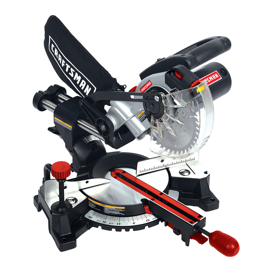
7-1/4 IN. COMPOUND
MITER SAW
MODEL
NO. 126.32564
CAUTION:
Before using this Miter Saw,
read this manual and follow
all its Safety Rules and
Operating Instructions.
• Safety Instructions
• Installation
• Operation
• Maintenance
• Troubleshooting
• Parts List
• Espa_ol
Sears Brands Management Corporation, Hoffman Estates, IL 60179 U.S.A.
Visit our Craftsman website: www.craftsman.com
Part No: 3848235
Advertisement

Related Manuals for Craftsman 126.32564


Summary of Contents for Craftsman 126.32564
- Page 1 • Operation • Maintenance all its Safety Rules and Operating Instructions. • Troubleshooting • Parts List • Espa_ol Sears Brands Management Corporation, Hoffman Estates, IL 60179 U.S.A. Visit our Craftsman website: www.craftsman.com Part No: 3848235...
-
Page 2: Table Of Contents
A defective product will receive free or replacement if repair is unavailable. For warranty coverage details to obtain free repair or replacement, visit the web site: www.craftsman.com This warranty does not cover the blade which is an expendable part that can wear out from normal use within the warranty period. - Page 3 MOTOR Power Source ....................120V, 60Hz, 7A Speed ......................5000RPM ( NoLoad) Double I nsulated ....................BLADE SIZE Diameter ......................7-1/4 in. Arbor size ......................5/8in. Blade T ype ................. 24T TCT (Tungsten Carbide Tipped). ROTATING TABLE Diameter ......................9 in.
- Page 4 WARNING ICONS Your power tool and its Operator's Manual may contain "WARNING ICONS" (a picture symbol intended to alert you to, and/or instruct you how to avoid a potentially hazardous condition). Understanding these symbols will help you operate your tool better and safer. Shown below are some of the symbols you may see: SAFETY ALERT: Precautions that involve your safety.
- Page 5 GENERAL SAFETY INSTRUCTIONS 7. MAKE WORKSHOP CHILD PROOF BEFORE USING THIS POWER TOOL with padlocks, master switches or by removing starter keys. Safety is a combination of common sense, 8. DO NOT FORCE THE TOOL. staying alert and knowing how to use your power tool.
- Page 6 19. CHECK FOR DAMAGED PARTS. ALWAYS wear Safety Goggles (not glasses) that comply with Before further use of the tool, a guard or ANSI Safety standard Z87.1. other part that is damaged should be carefully Everyday eyeglasses have only impact checked to determine that it will operate resistant lenses.
- Page 7 SPECIFIC SAFETY INSTRUCTIONS 10. BE SURE both the blade and the collar THIS COMPOUND MITER SAW are clean and the arbor bolt is tightened securely. 1. DO NOT USE THIN KERF BLADES they can deflect and contact guard and can 11.
- Page 8 21. USE THIS COMPOUND MITER SAW 26. SHUT OFF the power before servicing or ONLY FOR Wood and wood based materials. adjusting the tool. DO NOT use it to cut Stainless Steel, Masonry or Asbestos-based materials. 27. DISCONNECT the saw from the power source and clean the machine when cutting is finished.
-
Page 9: Product Specifications
To reduce the risk of electrical shock, this WARNING saw has a polarized plug (one blade is wider POWER SUPPLY AND MOTOR than the other). This plug will fit in a polarized SPECIFICATIONS outlet only one way. If the plug does not fit The AC motor used in this saw is a universal, fully in the outlet, reverse plug. - Page 10 The table below shows the correct size to If the blade is free, try to start the saw again. If the motor still does not start, refer to the use depending on cord length and nameplate TROUBLESHOOTING GUIDE. ampere rating. If in doubt use the next heavier gauge.
- Page 11 Do not use if any damage is suspected. Failure to heed safety ACCESSORIES instructions and warnings can result Visit your Sears Hardware Department or in serious bodily injury. see the Craftsman Power and Hand Tool Catalogue to purchase available accessories for this power tool.
- Page 12 SUPPLIED NOT SUPPLIED Adjustable Wrench Phillips Screwdriver Allen Key (Blade Change) Slotted Screwdriver Allen Key (Adjustments) ,I,1,t,t,I,I,1,1_1 Combination Square (Known to be accurate)
- Page 13 UNPACKING YOUR MITER SAW _I_ WARNING A, WARNING If any part is missing or damaged do To avoid injury from unexpected starting not attempt to assemble the miter or electrical shock, do not plug the saw, or plug in the power cord until power cord into a source of power during the missing or damaged part is unpacking and assembly.
- Page 14 LINE DIAGRAM OF MITER SAW LEFT SIDE VIEW 1 - UPPER BLADE GUARD 2 - AUXILIARY BLADE GUARD 3 - CUTTING HEAD HANDLE 4 - BLADE (housed inside clear bower blade guard) 5 - FENCE 6 - BEVEL LOCK HANDLE 7 - HOLD DOWN CLAMP 8 - DUST EXTRACTION PORT...
- Page 15 LINE DIAGRAM OF MITER SAW RIGHT SIDE VIEW 1 - LOWER BLADE GUARD 2 - TABLE 3 - CUTTING HEAD LATCHING PIN 4 - ON/OFF TRIGGER SWITCH 5 - MOUNTING HOLE (there are 4 mounting holes in total, 2 at the back and 2 at the front)
- Page 16 CUTTING H EAD LATCHING PIN - Locks AMPERAGE (AMPS) - Ameasure oftheflow ofelectric current. Higher ratings g enerally themiter s awinthelowered position for means thetoot i ssuited f orheavier use. compact storage and transportation. ARBOR - Theshaft onwhich t heblade is DOUBLE- INSULATED - A form ofelectrical mounted.
- Page 17 GUARD - Protective device that forms a ON/OFF TRIGGER SWITCH - To start the barrier between an hazardous object such as tool, squeeze the trigger. Release the trigger to turn the miter saw OFF. a blade, wheel or cutter and the operator. HOLD DOWN CLAMP - Secures the REVOLUTIONS PER MINUTE (RPM) -...
-
Page 18: Compound Miter Saw Safety
Locking the Cutting Head in the Down WARNING Position (Fig. B) To avoid injury from unexpected starting or electrical shock, do not plug the When not using, transporting or storing the power cord into a power source during miter Saw, lock the Cutting Head in the down unpacking or assembly. - Page 19 INSTALLING OR REMOVING A BLADE CAUTION Dispose of the contents of the dust I A, WARNING collection bag in an environmentally Only use blades which are designed for responsible way. It may be neccesary to this machine. wear a dust mask when emptying the dust Ensure that the maximum speed of the blade collection bag.
- Page 20 4. Rotate the bower blade guard upwards and back to reveal the saw blade and arbor bolt. (Fig. E) (Fig. E) 5 Press the arbor lock button to lock 9. Lock the arbor and tighten the arbor screw the arbor. (Fig. F) using moderate force, but do not overtighten.
- Page 21 MOUNTING THE MITER SAW 5. Bolt or clamp the saw securely to its support stand or workbench. _, WARNING To reduce the risk of injury from unexpected For portable use: saw movement, place the saw in the desired location either on a workbench or other 1.
- Page 22 0°Bevel S top Adjustment 1. Ensure that the Cutting Head is upright against its stop and the Bevel Pointer is indicating '0 °' on the scale. (Fig. J) (Fig. J) (Fig. L) 6. Use an Allen Key to turn the screw in or out to adjust the blade angle.
- Page 23 45 o Bevel Stop Adjustment WARNING 1. Loosen the Bevel Lock Handle and tilt the Cutting Head completely to the left until it When all angular adjustments have been rests against the 45 o stop. successfully completed, the operation of 2.
- Page 24 Miter Angle Pointer Adjustment NOTE: There are dual miter angle scales cast into the rotary table to the right hand side of the blade. A small pointer indicates the angle selected. If necessary the pointer can be repositioned by loosening its fastening screw using a #2 Phillips screwdriver.
-
Page 25: Electrical Requirements And Safety
SAFETY INSTRUCTIONS FOR BASIC The blade teeth should always point SAW OPERATION downwards at the front of the saw. Tighten the arbor bolt. BEFORE USING THE MITER SAW Check for damaged parts. Check for: Cracks in the blade, and for broken, WARNING chipped or missing blade teeth. - Page 26 AVAILABLE ACCESSORIES Plan ahead to protect your eyes, hands, face and ears. Consult the ACCESSORIES Know your miter saw. ATTACHMENTS section of this Read and understand this Operator's Manual and the labels affixed to the tool. Operator's Manual for the available accessories.
- Page 27 DRESS FOR SAFETY I A. WARNING j DO NOT OVER-REACH Any power tool can throw foreign objects into the eyes. This can result in To avoid serious blade cut injury, NEVER permanent eye damage. extend your arm or hand so that it is in the Everyday eyeglasses have only impact path of the blade.
- Page 28 or roller stands etc, adjusted so they are at the same height as the saw table, to prevent large workpieces from tipping or twisting when being cut. Never employ another person to hold or support a large or odd shaped workpiece, or to help feed the material into the saw.
- Page 29 THE LASER GUIDE Your saw is equipped with a Laser cutting guide using a Class 11 laser beam. The laser beam allows the operator to preview the path of the saw blade on the stock to be cut before starting the saw. The laser is powered by 2 'AAA' batteries located in the battery box positioned to the The use of optical instruments with this...
- Page 30 Release the trigger switch and allow the NOTE: The miter angle locking screw has an blade to come to a complete halt. adjustable spring loaded lever. This enables Raise the Cutting Head to its upper the lever to be repositioned on the locking position with the guard covering the screw.
- Page 31 MAKING A BEVEL CUT (Fig. U) MAKING A COMPOUND CUT (Fig. V) The Cutting Head can be set at any angle up A compound cut is a combination of a miter and bevel cut. to a 45 oto the Left Hand side only. The Bevel Angle Lock Handle is found at the Select the required miter angle as rear of the machine.
- Page 32 CUTTING BOWED MATERIAL Before cutting any workpiece, check to see if it is bowed. If it is bowed the workpiece must be positioned and cut as shown. (Fig. W) (Fig. W) Do not position the workpiece incorrectly or cut the workpiece without the support of the fence.
- Page 33 NOTE: Used but serviceable brushes can be DANGER reused, but only as long as they are inserted into the same position as they were when To avoid injury, never put lubricants on removed from the machine. the blade while it is spinning. Run new brushes without load for WARNING approximately 5 minutes.
- Page 34 Refer to INSTALLING OR REMOVING THE Apply light machine oil to the Chop Pivot bolt. BLADE section on page 19. (Fig. Y2) DUST COLLECTION BAG To maintain extraction efficiency empty the Dust Collection Bag when it becomes approximately 2/3 full. Dispose of the contents in an environmentally responsible manner.
-
Page 35: Troubleshooting Guide
WARNING To avoid injury from accidental starting, always turn switch OFF and unplug machine before attempting any maintenance or carrying out any adjustments to your miter saw. TROUBLE SHOOTING GUIDE - MOTOR PROBLEM PROBLEM CAUSE SUGGESTED CORRECTIVE ACTION Motor does not start. 1. - Page 36 TROUBLESHOOTING GUIDE - SAW OPERATION PROBLEM PROBLEM CAUSE SUGGESTED CORRECTIVE ACTION Blade hits the table or table 1. Incorrectly installed blade. 1. Check blade installation. insert. See INSTALLING OR REMOVING A BLADE section. Cutting head wobbles. 1. Loose pivot bolt.. 1.
- Page 37 "4 <...
- Page 38 026-0201 Stator 026-0001 Base Full Assembly 1 026-2460 Screw ST4.8x70 026-0022 Handle rotor Ass 026-0307 Top handle 026-0033 Head Assembly 026-0301 Handle (upper) 026-0044 Gear Assembly 026-0403 Trigger lever 026-4520 Screw M5x20 026-0308 Capacitor 0.33 026-0426 Washer 026-0304 Trigger Switch 026-6800 Screw M6x8 026-0305 Cable clamp...
- Page 39 026-0100 Base 026-6222 Washer 6x22x2 026-1006 Locking nut M6 026-0513 Under Protet plate 026-7405 ball bearing 8mm 026-0112 Spring 026-8100 screw MlOxlO 026-0512 screw M6x 11 026-0511 pad 026-0510 Screw M6xl 6mm 026-0104 Fence 026-4060 screw M4x6mm 026-0105 Blade throat 026-0501 Lock-screw 100.
- Page 41 • Mantenimiento todas las normas de seguridad e instrucciones de funcionamiento. • Soluci6n de problemas • Lista de piezas Sears Brands Management Corporation, Hoffman Estates, IL 60179, EE.UU. Visite el sitio Web de Craftsman: www.craftsman.com N° de pieza: 3848235...
- Page 42 Para obtener informaci6n detallada sobre la cobertura de la garantia para la reparaci6n o sustituci6n gratuitas de un producto, visite el sitio Web: www.craftsman.com Esta garantia no cubre la hoja ya que se trata de una pieza fungible que se puede desgastar durante su uso normal dentro del periodo de garantia.
- Page 43 MOTOR Fuente de atimentaci6n ..................120V, 60Hz, 7A Vetocidad ....................5000RPM (sin carga) Aislamiento dobte ........................TAMANO DE LA HOJA Di&metro ..........................7-1/4" Tama5o det &rbot ........................5/8" Tipo de hoja ..........24 dientes con TCT (puntas de carburo de tungsteno) MESA GIRATORIA Di&metro ...........................
- Page 44 ICONOS DE ADVERTENCIA En la herramienta electrica o en el Manual del operador correspondiente, puede haber "ICONOS DE ADVERTENCIA" (simbolos para avisarle y/o indicarle cbmo evitar una situacibn potencialmente peligrosa). Comprender estos simbolos le ayudara a utilizar la herramienta mejor y con mas seguridad.
- Page 45 INSTRUCCIONES GENERALES 5. NO UTILICE LA HERRAMIENTA SEGURIDAD ANTES DE UTILIZAR ESTA ENTORNOS PELIGROSOS. No utilice las HERRAMIENTA ELC:CTRICA herramientas etectricas en lugares humedos, ni las exponga a la Iluvia o a la nieve. La seguridad es una combinacion de sentido Mantenga el a.rea de trabajo bien iluminada.
- Page 46 amperaje indicado en la ptaca de identificacion. sujetar la pieza siempre que pueda. Es ma.s En caso de duda, utilice el calibre mayor ma.s seguro que utilizar la mano y las deja las dos proximo. Cuanto menor sea el calibre, mayor manos libres para manejar la herramienta.
- Page 47 20. NUNCA DEJE DESATENDIDA LA HERRAMIENTA EN FUNCIONAMIENTO. PONGA EL INTERRUPTOR EN LA POSICION "APAGADO'. No se aleje nunca dejando una herramienta en funcionamiento hasta que no se haya parado ta hoja por compteto y la herramienta se haya desenchufado de la fuente de atimentacion.
- Page 48 INSTRUCCIONES DE SEGURIDAD 8. MANTENGA LAS RANURAS DE ESPECiFICAS PARA ESTA SIERRA VENTILAClON DEL MOTOR LIMPIAS y sin INGLETADORA COMPUESTA virutas ni polvo. 1. NO UTILICE HOJAS CON UN ANCHO 9. ASEGURESE SIEMPRE de que todos DE CORTE FINO ya que pueden dobtarse y los mangos esten bien apretados antes de cortar, incluso si la mesa est&...
- Page 49 26. CORTE ta fuente de atimentaci6n de 18. ASEGORESE de que la hoja no este en contacto con la pieza de trabajo antes poner energia antes del mantenimiento o det ajuste de la herramienta. et interruptor en la posici6n de ENCENDIDO. 19.
- Page 50 ADVERTENCIA .." ESPECIFICACIONES DE LA FUENTE DE ALIMENTACION Y DEL MOTOR ..22112 El motor de CA utilizado en esta sierra es de tipo universal y no reversible. Vease "MOTOR" en la seccion Para reducir et peligro de descargas "ESPEClFICACIONES DEL PRODUCTO"...
- Page 51 CABLES CALIBRE MiNIMO DE LOS CABLES PROLONGADORES (AWG) Utilice un cable prolongador adecuado. Asegurese de que et cable prolongador (SOLo CUANDO LA CORRIENTE ES DE VOLTIOS) este en buen estado. Si utitiza un cable AMPERAJE L©NGITUD TOTAL DEL CABLE No MASDE 7.62 15.24 30.48...
- Page 52 ACCESORIOS lesiones corporales. Visite et departamento de ferreteria de Sears o consutte et cat&logo de herramientas etectricas y manuates de Craftsman para adquirir los accesorios disponibtes para esta herramienta etectrica.
- Page 53 PROPORClONADA NO PROPORClONADA Llave inglesa ajustable Destornillador Phillips Llave Allen (cambio de la hoja) Destornillador piano Llave Allen ,I,1,t,t,I,I,1,1_1 (ajustes) Escuadra combinada (conocida pot su precisibn)
- Page 54 DIAGRAMA LINEAL DE UNA VISTA LATERAL IZQUIERDA DE LA SIERRA INGLETADORA 1 - PROTECTOR SUPERIOR DE LA HOJA 2 - PROTECTOR AUXILIAR DE LA HOJA 3 - MANGO DEL CABEZAL DE CORTE 4 - HOJA (ALOJADA DENTRO DEL PROTECTOR INFERIORTRANSPARENTE DE LA HOJA) 5- GUiA 6- MANGO DE BLOQUEO DEL BISEL 7- PRENSA DE SUJECION...
- Page 55 DIAGRAMA LINEAL DE UNA VISTA LATERAL DERECHA DE LA SIERRA INGLETADORA 1 - PROTECTOR INFERIOR DE LA HOJA 2 - MESA 3 - PASADOR DE BLOQUEO DEL CABEZAL DE CORTE 4 - INTERRUPTOR DE GATILLO DE ENCENDIDO/APAGADO 5 - ORIFICIO DE MONTAJE (HAY 40RIFICIOS DE MONTAJE EN TOTAL, 2 EN LA PARTE POSTERIOR Y 2 EN LA PARTE FRONTAL)
- Page 56 DESEMBALAJE DE LA SIERRA ADVERTENCIA I INGLETADORA Si faltara alguna pieza o si estuviera daSada, no intente montar la sierra ADVERTENCIA ingletadora ni enchufar el cable de Para evitar lesiones por una puesta en alimentacibn hasta que la pieza que marcha inesperada o por descargas falta o daSada haya sido debidamente etectricas, no enchufe et cable de...
- Page 57 PASADOR DE BLOQUEO AMPERAJE (AMPS) - Una medida det flujo de corriente etectrica. Unos amperajes CABEZAL DE CORTE - BIoquea la sierra ma.s altos normatmente significan que ingletadora en la posicion inferior para un la herramienta es adecuada para una atmacenamiento y transporte compactos.
- Page 58 PROTECTOR - Dispositivo de proteccion ORIFIClOS DE MONTAJE - Se utiNzan para que forma una barrera entre un objeto montar la sierra ingletadora en una superficie petigroso tat como una hoja, disco o cuchilla de trabajo plana y estabte. INTERRUPTOR DE GATILLO DE y et operador.
- Page 59 ADVERTENCIA Para evitar lesiones por una puesta en marcha inesperada o por descargas electricas, no enchufe el cable de alimentacibn a ninguna fuente de alimentacibn ni durante el desembalaje ni durante el montaje. El cable de alimentacibn debe permanecer desenchufado siempre que se realicen (Fig.
- Page 60 INSTALACION DE LA BOLSA DE 4. Ajuste la prensa con et tornitlo de RECOGIDA DE POLVO madposa y et volante de mano de modo ta Acopte la bolsa de recogida de potvo en pieza de trabajo quede bien fijada a la base et orificio de extraccion de polvo.
- Page 61 accionamiento det protector inferior 5 Pulse et bot6n de btoqueo del a.rbot para introduciendo un destornitlador Phillips btoquearto. (Fig. F) a traves det atojamiento det pasador de btoqueo. (Fig. D) (Fig. F) (Fig. D) 6. Utilizando la Ilave Alien proporcionada, suette et tomilto det a.rbot para retirar la hoja.
- Page 62 contacto, vea DESPLAZAMIENTO CABEZAL DE CORTE en la pagina 26. MONTAJE DE LA SIERRA INGLETADORA Para reducir et riesgo de lesiones derivadas de un movimiento inesperado de la sierra, p6ngala en et lugar deseado sobre un banco de trabajo o sobre cuatquier otro soporte adecuado para la ma.quina.
- Page 63 INSTRUCClONES DE AJUSTE 1. Apriete los dispositivos de btoqueo de inglete y de bisel. Vease la secci6n FUNClONAMIENTO. ADVERTENClA I Para evitar lesiones como consecuencia 2. Para evitar lesiones como consecuencia de las particutas de polvo suspendidas de una descarga electrica o de una puesta en el aire, coloque ta sierra de modo que en marcha accidental, aseg=3rese que el otras personas o transeQntes no queden...
- Page 64 2.Cotoque una escuadra combinada sobre Utilice una Ilave Allen para atorniltar o lamesa ingtetadora conlaregla c ontra la desatornitlar et tornitlo y ajustar la inclinaci6n mesa yettat6n delaescuadra contra lahoja. de la hoja. (Fig. L ) Vuetva a poner et cabezat de corte en su posici6n vertical y vuetva a comprobar la atineaci6n angular con la escuadra combinada.
- Page 65 5.Afloje lacontratuerca del t ornilto d eajuste Ajuste de la guia (Fig. P) detbisel a 450. 6.Utitice u naIlave A llen para ajustar La guia se debe atinear a 900 (escuadra) ettornitlo d eajuste enrosca.ndolo respecto a una hoja correctamente instalada.
- Page 66 DESPLAZAMIENTO DEL CABEZAL DE CORTE Ajuste del desplazamiento descendente del cabezal de corte. (Fig. Q) Para evitar que la hoja entre en contacto con alguna parte de la base metalica de la m&quina, puede ajustarse el desplazamiento descendente del cabezal de corte. Baje el cabezal de corte y compruebe si la hoja est&...
- Page 67 INSTRUCCIONES DE SEGURIDAD PARA INSPECClONE LA SIERRA ANTES DE EL FUNCIONAMIENTO BASICO DE LA CADA USO SIERRA Desconecte la sierra ingletadora. Para evitar lesiones como consecuencia ANTES DE UTILIZAR LA SIERRA de una puesta en marcha accidental, INGLETADORA desenchufe la sierra antes de realizar cuatquier ajuste, incluidos la instatacion _I_ ADVERTENCIA 1 y los cambios de hoja.
- Page 68 de las piezas de la sierra ingletadora cabezal de corte todo Io que pueda. Gire fattara, estuviera dobtada, dafiada o rota a mano la hoja y compruebe la holgura. de cuatquier manera, o si no funcionaran Incline et cabezal de corte a un _tnguto las piezas electricas APAGUE la sierra y de biset de 450 y repita la prueba.
- Page 69 sierra ingtetadora en una fuente de ni alhajas (anillos, retojes, etc.). Pueden atimentacion. atascarse y atraerlo hacia las piezas moviles. Utitice calzado antideslizante. PLANIFIQUE EL TRABAJO Utilice la herramienta adecuada. Si tiene el pelo largo, recojaseto. permita que alguna herramienta o Arrema.nguese las mangas largas hasta arriba del codo.
- Page 70 EXTREME LAS PRECAUClONES de un posibte contragotpe. NUNCA extienda LAS PIEZAS DE TRABAJO GRANDES et brazo o la mano de modo que quede "en CON UNA FORMA IRREGULAR I{nea" con la trayectoria de corte de la hoja. Los cortes a putso son una de las causas principates de accidentes y jama.s deben Utilice soportes adicionates tales como reatizarse.
- Page 71 POSICION DEL CUERPO Y DE LAS OPERACIONES BASICAS DE LA SIERRA MANOS (Fig. R). Interruptor de gatillo de ENCENDIDO/ ADVERTENClA APAGADO (Fig. S) cerca o dentro de la "zona sin El interruptor de gatillo de ENCENDIDO/ APAGADO se encuentra ubicado en el No ponga nunca las manos manos".
- Page 72 LA GU|A LASER ADVERTENCIA ] Esta sierra est& equipada con una gufa Cuando la guia laser se enciende, se de corte de I&ser que utiliza un haz de irradia un rayo laser. Evite el contacto I&ser de Clase 11.El rayo I&ser permite directo de los ojos con el rayo laser.
- Page 73 REALIZACION DE UN CORTE BASICO cierre siempre el taller cuando se este utilizando. Guarde la herramienta en un AsegOrese de que la pieza de trabajo este armario seguro y cerrado con Ilave o similar firmemente fijada a la mesa de la sierra y donde no puedan acceder los usuarios no cualificados ni los niSos.
- Page 74 Gire la mesa al a.ngulo deseado segun Io indicado en la escuadra de escata de ingtetes. Btoquee la mesa en la posicion correcta utilizando et tornillo de btoqueo. Ponga en marcha la sierra y deje que alcance la velocidad ma.xima de funcionamiento antes de reatizar et corte Proceda con la reatizacion del corte segun Io...
- Page 75 Seleccione et a.nguto de biset requerido segun Io descrito anteriormente REALIZACION DE UN CORTE EN BISEL BASlCO. Compruebe la trayectoria del cabezat de corte y ajuste la guia segun sea necesario. Asegurese de que todos los tornitlos de ajuste/btoqueo esten bien apretados antes de la reatizacion de un corte.
- Page 76 Para evitar lesiones, nunca lubrique la NOTA: Las escobillas usadas pero utilizables hoja mientras gira. se pueden reemplazar pero s61o si se introducen en la misma posici6n que estaban ADVERTENCIA 1 cuando se extrajeron de la m&quina. Para evitar incendios o reacciones t6xicas, nunca utilice gasolina, nafta, Ponga en funcionamiento las escobillas...
- Page 77 para m&quinas ligero. Compruebe que el anillo de retenci6n este bien apretado, sobre todo despues de haber cambiado una hoja. (Fig. AA1) Consulte la seccibn INSTALACION DE LA BOLSA DE RECOGIDA DE POLVO en la pagina 18. BOLSA DE RECOGIDA DE POLVO i\\\\\ O Para mantener la eficacia de extracci6n, vacie la bolsa de recogida de polvo cuando...
- Page 78 ADVERTENCIA Para evitar lesiones como consecuencia de una puesta en marcha accidental, APAGUE siempre el interruptor y desenchufe la maquina antes de realizar cualquier tarea de mantenimiento o de realizar cualquier ajuste en la sierra ingletadora. GU|A DE SOLUCION DE PROBLEMAS - MOTOR PROBLEMA CAUSA DEL PROBLEMA MEDIDAS CORRECTIVAS...
- Page 79 GU|A DE SOLUCION DE PROBLEMAS - FUNCIONAMIENTO DE LA SIERRA PROBLEMA CAUSA DEL PROBLEMA MEDIDAS CORRECTIVAS SUGERIDAS La hoja golpea la mesa o el 1. La hoja est& mal instalada.. 1. Compruebe la instalaci6n de la inserto de la mesa. hoja.
- Page 80 Your Home For troubleshooting, product manuals and expert advice: www.managemylife.com For repair - in your home - of all major brand appliances, lawn and garden equipment, or heating and cooling systems, no matter who made it, no matter who sold it! For the replacement parts, accessories owner's manuals that you need to do-it-yourself.