Table of Contents
Advertisement
G B
The information contained in this document may be modified without prior notice.
No part of this document may be reproduced and/or disclosed to third parties or competitors.
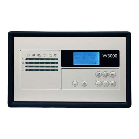
W3000
Second Edition
USER MANUAL
C0240102-01-10-GB
For software versions GA07
Replaces C0240102-10-09-GB
CLIMAVENETA S.p.A
Via Sarson, 57C
36061 Bassano del Grappa(VI)-ITALY
Tel. (+39) 0424 509 500
Fax (+39) 0424 509 509
http://www.climaveneta.it/
mailto:info@climaveneta.it
January 2010
H
H
Advertisement
Table of Contents

Related Manuals for CLIMAVENETA W3000 compact


Summary of Contents for CLIMAVENETA W3000 compact
- Page 1 W3000 Second Edition USER MANUAL C0240102-01-10-GB For software versions GA07 Replaces C0240102-10-09-GB CLIMAVENETA S.p.A Via Sarson, 57C 36061 Bassano del Grappa(VI)-ITALY Tel. (+39) 0424 509 500 Fax (+39) 0424 509 509 http://www.climaveneta.it/ mailto:info@climaveneta.it The information contained in this document may be modified without prior notice.
-
Page 2: Table Of Contents
C0240102-01-10-GB Contents USER INTERFACE ........................ 4 Language selection ....................... 5 Menu structure ......................6 Switching the unit on and off ..................8 Setting the operating mode ................... 9 Symbols ........................10 ... - Page 3 C0240102-01-10-GB The W3000 SE controller software is protected by a digital signature. Caution: This means that it can only work on boards supplied by Climaveneta and not on boards purchased from other dealers.
-
Page 4: User Interface
C0240102-01-10-GB USER INTERFACE There are two types of user interface: W3000 compact W3000 Depending on the type of user interface installed, there are more or less keys available for controlling the unit and for accessing system information. Description W3000 W3000 compact [MENU key]: accesses the main menu. -
Page 5: Language Selection
C0240102-01-10-GB Language selection A special feature of the new hardware is that is has an additional memory containing all the supported languages: Italian, English, German, Spanish, French, Russian and Swedish. To select any one of the available languages, proceed as follows. Press [ALARM] and [ENTER] together and hold down until the mask >... -
Page 6: Menu Structure
C0240102-01-10-GB Once the operation has finished, the masks will appear in the W 3000 SE selected language. The installed language can be checked in the “Unit“ menu. Code GA 00.00 GB IT Italian, GB English, DE German, ES Spanish, FR ... - Page 7 C0240102-01-10-GB The menus are briefly described below: The “Unit Menu” displays information such as temperature, pressure and circuit states. The “Setpoint menu” is used to set the setpoints for the various available functions. Different setpoints can be set depending on the available operating modes (chiller, heat pump and recovery).
-
Page 8: Switching The Unit On And Off
C0240102-01-10-GB 1.3 Switching the unit on and off Caution: connect the unit to the power supply at least 8 hours before starting it; if this is not done, the guarantee will become null and void. There are different procedures for starting or stopping the unit: using the user interface keys or selecting from the display. -
Page 9: Setting The Operating Mode
C0240102-01-10-GB For W3000 and W3000 compact (if the clock board is fitted) Make sure that the “Clock board not installed” is not displayed in the “clock menu”. Check that the “Time bands enabled” parameter in the “user menu” is set to “Yes”. ... -
Page 10: Symbols
C0240102-01-10-GB Make sure the unit is “Off”. Access the “setpoint menu” and display the “Operating mode” parameter. Move to the “Operating mode” parameter by pressing [Enter] and modify the parameter by pressing [Up] or [Down]. Press [Enter] again to confirm. If the set message continues to be displayed it means that the operating mode has been changed. -
Page 11: Symbols Available On Individual Machines
C0240102-01-10-GB Flashing Description items main mask BANDS Time bands active FCOOL Unit in free-cooling mode LIMIT Power limit active (demand limit) FREEZE Outlet temperature approaching anti-freeze setpoint ERR Y3 Analogue output configuration error. Switch the controller off and back on again U.ALONE The unit works independently after disconnecting the Manager3000 or Sequencer HPTC... -
Page 12: Setting Adjustment Methods
C0240102-01-10-GB 1.6 Setting adjustment methods Depending on the type of compressor used, various adjustment methods may be selected. Compressor Type of unit Adjustment method Water/water heat pump Water/water chiller Quick Mind on outlet probe Evaporating units Quick Mind on inlet probe Water/air heat pump ... -
Page 13: Proportional Step Adjustment On Inlet Probe
C0240102-01-10-GB 1.6.1 Proportional step adjustment on inlet probe Some examples of proportional “step” adjustment on the inlet temperature probe: Chiller (n° steps =2) Caso chiller (n° di gradini = 2) 100% Set + proportional band/2 Set + banda proporzionale/2 proportional band Banda proporzionale Figure 1.4: T i s the input variable, N... - Page 14 C0240102-01-10-GB The following tables show some typical values for the parameters in question. The theoretical maximum and minimum outlet temperature values refer to operation at nominal flow rates (with a thermal head at the evaporator of 5 °C and sufficient water in the system to ensure a litre / KW ratio equal to or greater than 7). N°...
-
Page 15: Proportional Step Adjustment On Inlet Probe + Integral On Inlet Probe
C0240102-01-10-GB 1.6.2 Proportional step adjustment on inlet probe + integral on inlet probe This adjustment method is based on the sum of two components: proportional and integral. The proportional component generates the percentage demand for activating/deactivating the steps, as illustrated in the previous paragraph “Proportional step adjustment on inlet probe”. The integral component adds the integral error to the proportional component at regular intervals (integral time: parameter 55.02). -
Page 16: Quick Mind Adjustment
C0240102-01-10-GB 1.6.3 Quick mind adjustment Users must set the required setpoint as the other parameters are adapted to the system by the Quick Mind algorithm. QUICK MIND is a self-adapting algorithm for adjusting the temperature of the water treated by an all-in- one unit. - Page 17 C0240102-01-10-GB 2 compressors - with maximum permitted number of start-ups per hour 10 Litres / KW 10.5 out 4 compressors - with maximum permitted number of start-ups per hour 10 Litres / KW 10.5 out 6 compressors - with maximum permitted number of start-ups per hour 10 Litres / KW 10.5 out...
-
Page 18: Modulating Adjustment Of Screw Compressors
C0240102-01-10-GB 1.6.4 Modulating adjustment of screw compressors With screw compressors, modulating adjustment is performed on the outlet probe. Modulating adjustment is only available on “Bitzer” screw compressors. Reference is made to the figure to the left: The setpoint remains within a dead area. If Tout [°C] the temperature also remains within this zone, no change is made to the number of... -
Page 19: Flexible Step Proportional Adjustment On Inlet + Dip On Outlet Probe
C0240102-01-10-GB 1.6.5 Flexible step proportional adjustment on inlet + DIP on outlet probe This adjustment is performed by two independent adjusters: a) Proportional step (step adjuster) on the inlet probe; b) DIP (fine adjustment) on the outlet probe. The set point is identical for both adjusters. a) This is a proportional step adjuster whose control variable is the inlet temperature to the Tin unit and whose controlled variable is the number of steps to enable (compressors). - Page 20 C0240102-01-10-GB The Offset moves the enable/disable of the second half of the steps to a higher value with respect to offset = 0. Operating example of 4 cooling steps and Offset > 0 Esempio funzionamento 4 gradini in raffreddamento e Offset > 0 Active steps Gradini attivi Caso offset = 0...
-
Page 21: Neutral Zone Adjustment On Outlet Probe + Pid On Outlet Probe
C0240102-01-10-GB 1.6.6 Neutral zone adjustment on outlet probe + PID on outlet probe This adjustment is performed by two independent adjusters: a) Neutral zone (step adjuster) on the outlet probe; b) DIP (fine adjustment) on the outlet probe. The set point is identical for both adjusters. a) This is a neutral zone step adjuster whose control variable is the outlet temperature from the Tout unit and whose controlled variable is the number of steps to enable (compressors). -
Page 22: Alarms
C0240102-01-10-GB ALARMS Press the [ALARM] key once to enter the “alarms menu” and view the alarm message along with its code. If there is more than one alarm, scroll the menu using the [UP] and [DOWN] keys. In the W3000 base, “NO A” is displayed if there is no alarm, otherwise the alarm code appears. Press any other key to exit from this menu. - Page 23 C0240102-01-10-GB ALARM DESCRIPTION DETAILS RESET Low water temperature at condenser outlet. Except for W3000 base, it also specifies which condenser (if more than one) is involved in the alarm condition. The alarm also appears if the antifreeze limit trips more than 5 times in 8 operating hours (only for Condenser antifreeze water/water units with freon reversal).
- Page 24 C0240102-01-10-GB ALARM DESCRIPTION DETAILS RESET Compressor 2 maintenance “as above, for compressor 2" Compressor 3 maintenance “as above, for compressor 3” Compressor 4 maintenance “as above, for compressor 4” “as above, for compressor 5” Compressor 5 maintenance Compressor 6 maintenance “as above, for compressor 6”...
- Page 25 C0240102-01-10-GB ALARM DESCRIPTION DETAILS RESET Compressor 3 inverter temperature “as above, for compressor 3” Compressor 4 inverter temperature “as above, for compressor 4” Compressor 1 discharge overtemperature (only Compressor 1 discharge temperature for units with centrifuge compressors) Compressor 2 discharge temperature “as above, for compressor 2”...
- Page 26 C0240102-01-10-GB ALARM DESCRIPTION DETAILS RESET Exp 2 Probe 3 error “analogue, as above” Exp 2 Probe 4 error “analogue, as above” Exp 2 Probe 5 error “analogue, as above” “analogue, as above” Exp 2 Probe 6 error Exp 2 Probe 7 error “analogue, as above”...
- Page 27 C0240102-01-10-GB ALARM DESCRIPTION DETAILS RESET High pressure in circuit 4 pre-alarm “as above, for circuit 4" No communication with the inverter on compressor 1 (only for units with screw Inverter 1 offline compressors with inverter) Inverter 2 offline “as above, for compressor 2” Inverter 3 offline “as above, for compressor 3”...
- Page 28 C0240102-01-10-GB ALARM DESCRIPTION DETAILS RESET Inverter 4 communication alarm “as above, for compressor 3" Safety input alarm on inverter of compressor 1 (only for units with screw compressors with Inverter 1 safety input alarm inverter) Inverter 2 safety input alarm “as above, for compressor 3"...
-
Page 29: Table Of Masks
C0240102-01-10-GB 3 TABLE OF MASKS Press [UP] or [DOWN] to move from one mask to another inside the same menu. Press [ENTER] to access the parameter, press [UP] or [DOWN] to change the value of the parameter. Mask Description Par.N. 09:26 ALXXX Main display mask. - Page 30 C0240102-01-10-GB Mask Description Par.N. Enable time Activates/deactivates time bands. The time bands cannot be activated if the external 39.41 bands : setpoint is enabled. Disabled Serial line Allows the devices connected to the serial interface board to be enabled and selected ( 39.42 configuration: "0"=disabled, "1"= supervision, "2"= sequencer, "3"=Manager 3000).
- Page 31 C0240102-01-10-GB Mask Description Par.N. Access mask to clock menu. Press "Up" or "Down" to scroll the other masks and "Esc" to return to the submenu. Clock Mask showing that the clock board is missing or damaged. Clock board not installed Clock Current date and time settings.
- Page 32 C0240102-01-10-GB Mask Description Par.N. Time band 5A Off Setting band A, fifth and sixth daily time band. 901.25 Time 19:30 / 19:30 901.26 Sp E 08.0°C I 40.0°C 901.27 Sp R 40.0°C 901.28 Time band 6A Off 901.29 Time 19:30 / 19:30 901.30 Sp E 08.0°C I 40.0°C 901.31...
- Page 33 C0240102-01-10-GB Mask Description Par.N. Time band 7B Off Setting band B, seventh and eighth daily time band. 902.37 Time 19:30 / 19:30 902.38 Sp E 09.0°C I 40.0°C 902.39 Sp R 40.0°C 902.40 Time band 8B Off 902.41 Time 19:30 / 19:30 902.42 Sp E 09.0°C I 40.0°C 902.43...
- Page 34 C0240102-01-10-GB Mask Description Par.N. Time band 9C Off Setting band C, ninth and tenth daily time band. 903.49 Time 19:30 / 19:30 903.50 Sp E 09.0°C I 40.0°C 903.51 Sp R 40.0°C 903.52 Time band 10C Off 903.53 Time 19:30 / 19:30 903.54 Sp E 09.0°C I 40.0°C 903.55...
- Page 35 C0240102-01-10-GB Mask Description Par.N. Access mask to In/Out menu. Press "Up" or "Down" to scroll the other masks and "Esc" to return to the submenu. In/Out Dig. In. 12345 67890 Displays the state of the digital inputs and outputs and specifies their number. master CCCCC CCCCC C: Contact closed...
- Page 36 C0240102-01-10-GB Mask Description Par.N. An. In. master exp2 Displays analogue inputs 1, 2, 3, 4, 5 and 6 of expansion 2 (if present). N° Value Master is only specified on units with 3 or 4 circuits. 04.2 bar 03.9 bar 35.6 °C 40.5 °C 22.3 °C...
- Page 37 C0240102-01-10-GB Mask Description Par.N. An. Out. master exp5 Voltage applied to analogue output 1 of expansion 5 (if present). N° Value Master is only specified on units with 3 or 4 circuits. 00.0 V Dig. In. 12345 67890 Displays the state of the digital inputs and outputs and specifies their number. slave CCCCC CCCCC C: Contact closed...
- Page 38 C0240102-01-10-GB Mask Description Par.N. An. In. slave exp2 Displays analogue inputs 1, 2, 3, 4, 5 and 6 of slave expansion 2 (if present for 3 or 4 N° Value circuit units). 04.2 bar 03.9 bar 35.6 °C 40.5 °C 22.3 °C 24.2 °C An.
- Page 39 C0240102-01-10-GB Mask Description Par.N. An. Out. slave exp5 Voltage applied to analogue output 1 of expansion 5 (if present). N° Value 00.0 V Access mask to setpoint menu. Press "Up" or "Down" to scroll the other masks and "Esc" to return to the submenu.
- Page 40 C0240102-01-10-GB Mask Description Par.N. Temp. Out. Displays inlet and outlet temperatures of the evaporator, recuperator and condenser Evap. 12.5 07.0°C (where fitted). Rec. 35.6 40.5°C In units with 2 evaporators, if the shared outlet probe is disabled, the average temperature Cond.
- Page 41 C0240102-01-10-GB Mask Description Par.N. Circ defr T.del T.dur Displays the defrosting status, the delay before defrosting starts and the time taken to 0904 0000 defrost. 0000 0028 0904 0000 0000 0028 Compressor discharge Displays the discharge temperature (if probes are present) of compressors. temperature C1:105.9 C2:058.2...
- Page 42 C0240102-01-10-GB Mask Description Par.N. Work Displays the operating status of the centrifuge compressors, the active percentage, the << 082% rpm and the percentage delivered. Also displays other data relative to the centrifuge compressors, such as outlet temperature and inlet pressure 32450 03.9bar discharge temp.
- Page 43 C0240102-01-10-GB Mask Description Par.N. Inverter 4: Online Displays whether inverter 4 is online with the controller. Also displays the command and Command 1400 rpm the effective speed of rotation of the screw compressor with inverter. Revs 1400 rpm Enable Selects/deselects circuits and compressors. 47.01 circuits 47.02...
Need help?
Do you have a question about the W3000 compact and is the answer not in the manual?
Questions and answers