Advertisement
Available languages
Available languages
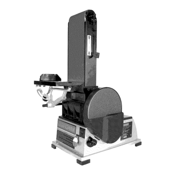
Operator's Manual
6 x 48" Belt, 9" Disc
SANDER WITH DUST COLLECTION
Model No.
351.217570
CAUTION:
Read and follow
all Safety Rules and Operating
Instructions
before First Use
of this Product. Keep this
manual with tool.
Sears, Roebuck and Co., Hoffman
Estates, IL 60179 U.S.A.
www.sears.com/craftsman
24675.00 Draft (06/01/06)
Advertisement
Table of Contents

Related Manuals for Craftsman 351.217570


Summary of Contents for Craftsman 351.217570
- Page 1 SANDER WITH DUST COLLECTION Model No. 351.217570 CAUTION: Read and follow all Safety Rules and Operating Instructions before First Use of this Product. Keep this manual with tool. Sears, Roebuck and Co., Hoffman Estates, IL 60179 U.S.A. www.sears.com/craftsman 24675.00 Draft (06/01/06)
- Page 2 ON CRAFTSMAN TOOL • Keep all parts in working order. Check to determine that the If this Craftsman tool fails due to a defect in material or guard or other parts will operate properly and perform their intended function. workmanship within one year from the date of purchase CALL 1-800-4-MY-HOME®...
-
Page 3: Tools Needed
° Sander can be installed on a workbench or a tool stand (see Recommended Accessories, page 15) using bolts, lock washers and hex nuts (not supplied). Refer to Figure 1. ° Figure 2 shows the base dimensions, mounting holes and Check for shipping damage. -
Page 4: Power Source
* Loosen knob. Using a combination square, set the table perpendicular to the disc, and secure in position. If necessary, set pointer at 0°. To use the table with the belt: * Loosen bolt in pivot bracket. (see Adjusting Belt Assembly Position, page 7). - Page 5 • Many cover plate screws, water pipes and outlet boxes are DESCRIPTION not properly grounded. To ensure proper ground, grounding The Craftsman Belt and Disc Sanders are constructed means must be tested by a qualified electrician. rugged die cast aluminum and cast iron providing stability and vibration-free operation.
-
Page 6: Specifications
SPECIFICATIONS Some examples of these chemicals are: ° Lead from lead-based paints. MODEL 217570 ° Crystalline silica from bricks and cement and other Belt size ........6 x 48" masonry products. Belt platen area ......6 x 13W' ° Arsenic and chromium from chemically-treated lumber. - Page 7 ADJUSTING TABLE ANGLE Refer to Figure 12. ° To adjust table angle, loosen knob, tilt table to desired position, then secure by tightening knob. ° Reposition table on support rod to ensure that gap between table and belt (disc) is '/_" or less. To reposition table, loosen bolt, move table on rod and secure in position by tightening bolt.
- Page 8 * Finishing long pieces: Usebelt i nhorizontal position with ° If table needs adjustment, loosen the three bolts beneath work stop. A pply o nlyenough p ressure toallow abrasive table, move table and secure in position. belt t oremove material. Usework stop toposition andsecure w ork being sanded.
-
Page 9: Replacing Abrasive Disc
• Slide new belt over the drive and idler drums; center belt on drums. • Additional abrasive belts are available (See Recommended WARNING: Make certain that the unit is disconnected from Accessories, page 15). power source before attempting to service or remove any •... - Page 10 SYMPTOM CORRECTIVE ACTION POSSIBLE CAUSE(S) Motor will not start 1. Low voltage 1. Check power line for proper voltage 2. Open circuit in motor or loose 2. Inspect all lead connections on motor for loose or connections open connection 3. Defective switch 3.
-
Page 11: Service Record
Service Record Craftsman Sander with Dust Collection I DATE MAINTENANCE PERFORMED REPLACEMENT PARTS REQUIRED... - Page 12 Models 351.217570 Figure 19 - Replacement Parts Illustration for Belt Housing j_/8 31 _3...
- Page 13 PART DESCRIPTION QTY. 21425.00 Idler Assembly STD840610 6-1.0ram Hex Nut* STD843610 6-1.0mm Fiber Hex Nut* 21426.00 Spring Platen 24628.00 STD833025 6-1.0 x 25mm Hex Head Bolt* 21428.00 Tension Lever Abrasive Belt 20768.00 STD870820 8-1.25 x 20mm Socket Head Bolt* STD840812 8-1.25mm Hex Nut* 21430.00...
- Page 14 Models 351.217570 Figure 20 - Replacement Parts Illustration for Motor and Disc 8 22...
- Page 15 PART NO. DESCRIPTION QTY. STD870510 5-0.8 x 10mm Socket Head Bolt 07202.00 8-1.25 x 10mm Set Screw STD870616 6-1.0 x 16mm Socket Head Bolt* STD851006 6mm Flat Washer* 5-0.8 x 10mm Pan Head Screw* STD863510 24645.00 V-Belt 24646.00 Disc Guard 5mm Flat Washer* STD8451005 5-0.8 x 35mm Socket Head Bolt*...
- Page 16 Ilaves del arrancador para impedir GARANTIA COMPLETA DE UN AI_IO PARA HERRAMIENTA cualquier uso involuntario de las herramientas mecanicas. CRAFTSMAN SE DEBE DAR MANTENIMIENTO A LA HERRAMIENTA Siesta herramienta Craftsman fallara por causa de defectos en el...
- Page 17 ,, Evite que la herramienta se encienda accidentalmente. AsegL_rese que el interrupter de la herramienta esta en la posici6n OFF (apagado) antes de enchufarla. ,, No fuerce la herramienta. Funcionara en la forma mas eft- Consulte las Figuras 2-5. ciente a la velocidad para la cu_.l se dise_6.
- Page 18 INSTALACION DEL CONJUNTO DE LA MESA Consulte las Figuras 3 y 4. El conjunto de mesa incluido se utiliza con ambos, el disco y la correa. Para utilizar la mesa con el disco: ,, Inserte la varilla de soporte de la mesa en la base de la lijadora.
- Page 19 las Normas para Instalaciones Electricas (National Electric Code) y los c6digos y regulaciones locales. ADVERTENCIA: Esta tarea debera ser realizada por un Consulte las Figuras 6, 7 y 8 en las paginas 19 y 20. electricista calificado. Se puede usar temporalmente un adaptador de 3 puntas a 2 FUENTE...
- Page 20 DESCRIPClON miento antes de comenzar a lijar o esmerilar. La Lijadora de correa y disco de Craftsman esta construida • Asegurese que el disco gire en el sentido de las manillas aluminio...
- Page 21 una mascara para la cara o respirador adecuadamente ajusta- dos, aprobados por OSHA/NIOSH. INTERRUPTOR DE ON/OFF (ENCENDIDO/APAGADO) Consulte la Figura 9. El interruptor de encendido y apagado se encuentra en la parte delantera superior derecha del gabinete. Para encender la lijado- ra, cambie la posici6n del interruptor a la posici6n...
- Page 22 AJUSTE DEL ANGULO DE LA MESA USO DE LA CORREA ABRASIVA PARA TRABAJOS DE ACABADO Consulte la Figura 12. • Acabado de las superficies planas: Sujete firmemente la pieza • Para ajustar el angulo de la mesa, afloje la manilla, incline de trabajo con las dos manos;...
-
Page 23: Cambio De La Correa
• Despu@s de cuadrar la mesa y la guia de ingletes con la correa (o el disco), cambie la posici6n del indicador de &ngulo en la escala de la gufa de ingletes para ajustar la guia al angulo deseado y ffjela en esa posici6n con la manilla. CAMBIO DE LA CORREA ABRASIVA... - Page 24 CAMBIO DEL DISCO ABRASlVO Consulte la Figura 18. ,, Desmonte el conjunto de la mesa. ADVERTENClA: AsegL_rese de que la unidad este desconecta- ,, Retire la cubierta del disco. Para esto, afloje y extraiga cinco da de la fuente de alimentaci6n electrica antes de tratar de dar tomillos.
- Page 25 SINTOMA MEDIDA CORRECTIVA CAUSA(S) POSIBLE(S) El motor no arranca 1. Voltaje bajo 1. Verifique el voltaje correcto de la Ifnea de alimentacion 2. Circuito abierto en el motor o 2. Inspeccione todas las conexiones de conductores conexiones sueltas en el motor para ver que no haya conexiones sueltas o abiertas 3.
- Page 26 NOTAS...
- Page 27 NOTAS...
- Page 28 Your Home For repair- in your home-of all major brand appliances, lawn and garden equipment, or heating and cooling systems, no matter who made it, no matter who sold it! For the replacement parts, accessories owner's manuals that you need to do-it-yourse For Sears professional installation of home appliances and items like garage door openers and water heaters.