Table of Contents
Advertisement
Advertisement
Table of Contents
Troubleshooting

Subscribe to Our Youtube Channel
Related Manuals for Gigabyte GA-Z77MX-D3H


Summary of Contents for Gigabyte GA-Z77MX-D3H
- Page 1 GA-Z77MX-D3H User's Manual Rev. 1001 12ME-Z77MXD3-1001R...
-
Page 3: Identifying Motherboard Revision
GIGABYTE's prior written permission. Documentation Classifications In order to assist in the use of this product, GIGABYTE provides the following types of documentations: For quick set-up of the product, read the Quick Installation Guide included with the product. -
Page 4: Table Of Contents
Table of Contents Box Contents ........................6 Optional Items .........................6 GA-Z77MX-D3H Motherboard Layout ................7 GA-Z77MX-D3H Motherboard Block Diagram ..............8 Chapter 1 Hardware Installation ..................9 Installation Precautions ................... 9 Product Specifications ................... 10 Installing the CPU and CPU Cooler............... 13 1-3-1 Installing the CPU ....................13 1-3-2 Installing the CPU Cooler ..................15... - Page 5 Chapter 3 Drivers Installation ..................55 Installing Chipset Drivers ................55 Application Software ..................56 Technical Manuals ..................56 Contact......................57 System ......................57 Download Center ................... 58 New Program ....................58 Chapter 4 Unique Features ...................59 Xpress Recovery2 ..................59 BIOS Update Utilities ..................
-
Page 6: Box Contents
Box Contents GA-Z77MX-D3H motherboard Motherboard driver disk User's Manual Quick Installation Guide Two SATA 6Gb/s cables Two SATA 3Gb/s cables I/O Shield One 2-Way SLI bridge connector The box contents above are for reference only and the actual items shall depend on the product package you obtain. -
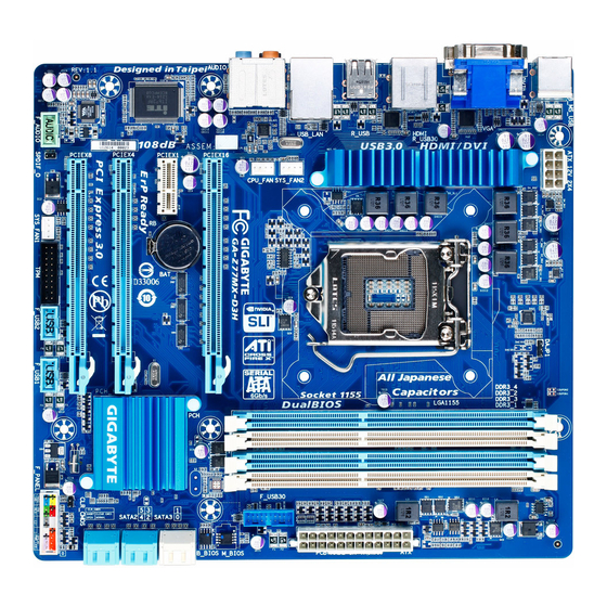
Page 7: Ga-Z77Mx-D3H Motherboard Layout
GA-Z77MX-D3H Motherboard Layout KB_USB ATX_12V LGA1155 R_USB30 HDMI R_USB USB_LAN SYS_FAN2 CPU_FAN AUDIO Atheros M_BIOS GA-Z77MX-D3H GbE LAN PCIEX16 B_BIOS PCIEX1 SATA3 SATA2 Intel PCIEX4 ® CODEC PCIEX8 CLR_CMOS F_PANEL F_AUDIO SPDIF_O SYS_FAN1 F_USB2 F_USB1 - 7 -... -
Page 8: Ga-Z77Mx-D3H Motherboard Block Diagram
GA-Z77MX-D3H Motherboard Block Diagram 2 PCI Express x8 1 PCI Express x16 CPU CLK+/- (100 MHz) LGA1155 DDR3 1600 /1333/1066 MHz (Note 1) PCIe CLK Dual Channel Memory (100 MHz) Switch Dual BIOS PCI Express Bus 2 SATA 6Gb/s HDMI... -
Page 9: Chapter 1 Hardware Installation
Chapter 1 Hardware Installation Installation Precautions The motherboard contains numerous delicate electronic circuits and components which can become damaged as a result of electrostatic discharge (ESD). Prior to installation, carefully read the user's manual and follow these procedures: Prior to installation, make sure the chassis is suitable for the motherboard. •... -
Page 10: Product Specifications
* To support DDR3 1600 MHz, you must install an Intel 22nm (Ivy Bridge) CPU. Support for non-ECC memory modules Š Support for Extreme Memory Profile (XMP) memory modules Š (Go to GIGABYTE's website for the latest supported memory speeds and memory modules.) Onboard Integrated Graphics Processor: Š... - Page 11 Storage Interface Chipset: Š 2 x SATA 6Gb/s connectors (SATA3 0/1) supporting up to 2 SATA 6Gb/s devices 4 x SATA 3Gb/s connectors (SATA2 2/3/4/5) supporting up to 4 SATA 3Gb/s devices Support for RAID 0, RAID 1, RAID 5, and RAID 10 * When a RAID set is built across the SATA 6Gb/s and SATA 3Gb/s channels, the system performance of the RAID set may vary depending on the devices being connected.
- Page 12 Support for Microsoft Windows 7/XP Š ® System Form Factor Micro ATX Form Factor; 24.4cm x 24.4cm Š * GIGABYTE reserves the right to make any changes to the product specifications and product-related information without prior notice. Hardware Installation - 12 -...
-
Page 13: Installing The Cpu And Cpu Cooler
Read the following guidelines before you begin to install the CPU: Make sure that the motherboard supports the CPU. • (Go to GIGABYTE's website for the latest CPU support list.) Always turn off the computer and unplug the power cord from the power outlet before installing the •... - Page 14 B. Follow the steps below to correctly install the CPU into the motherboard CPU socket. Before installing the CPU, make sure to turn off the computer and unplug the power cord from the power outlet to prevent damage to the CPU. Step 1: Step 2: Remove the CPU socket cover as shown.
-
Page 15: Installing The Cpu Cooler
1-3-2 Installing the CPU Cooler Follow the steps below to correctly install the CPU cooler on the motherboard. (The following procedure uses Intel boxed cooler as the example cooler.) ® Male Push Pin Direction of the Arrow Sign The Top on the Male of Female Push Pin... -
Page 16: Installing The Memory
• same capacity, brand, speed, and chips be used. (Go to GIGABYTE's website for the latest supported memory speeds and memory modules.) Always turn off the computer and unplug the power cord from the power outlet before installing the •... -
Page 17: Installing A Memory
1-4-2 Installing a Memory Before installing a memory module, make sure to turn off the computer and unplug the power cord from the power outlet to prevent damage to the memory module. DDR3 and DDR2 DIMMs are not compatible to each other or DDR DIMMs. Be sure to install DDR3 DIMMs on this motherboard. -
Page 18: Installing An Expansion Card
Installing an Expansion Card Read the following guidelines before you begin to install an expansion card: Make sure the motherboard supports the expansion card. Carefully read the manual that came • with your expansion card. Always turn off the computer and unplug the power cord from the power outlet before installing an •... -
Page 19: Setting Up Amd Crossfirex ™ /Nvidia Sli Configuration
Setting up AMD CrossFireX /NVIDIA SLI Configuration ™ A. System Requirements Windows 7 or Windows XP operating system A CrossFireX/SLI-supported motherboard with two PCI Express x16 slots and correct driver Two CrossFireX/SLI-ready graphics cards of identical brand and chip and correct driver CrossFireX /SLI bridge connector (Note) -
Page 20: Back Panel Connectors
Back Panel Connectors USB 2.0/1.1 Port The USB port supports the USB 2.0/1.1 specification. Use this port for USB devices such as a USB keyboard/mouse, USB printer, USB flash drive and etc. PS/2 Keyboard/Mouse Port Use this port to connect a PS/2 mouse or keyboard. D-Sub Port The D-Sub port supports a 15-pin D-Sub connector. - Page 21 Dual Display Configurations for the Onboard Graphics: This motherboard provides three video output ports: D-Sub, DVI-D, and HDMI. Dual monitor confgurations are supported in operating system environment only, but not during the BIOS Setup or POST process. RJ-45 LAN Port The Gigabit Ethernet LAN port provides Internet connection at up to 1 Gbps data rate.
-
Page 22: Internal Connectors
Internal Connectors ATX_12V F_PANEL F_AUDIO CPU_FAN SPDIF_O SYS_FAN1/2 F_USB1/F_USB2 F_USB30 SATA3 0/1 SATA2 2/3/4/5 CLR_CMOS Read the following guidelines before connecting external devices: First make sure your devices are compliant with the connectors you wish to connect. • Before installing the devices, be sure to turn off the devices and your computer. Unplug the power •... - Page 23 1/2) ATX_12V/ATX (2x2 12V Power Connector and 2x12 Main Power Connector) With the use of the power connector, the power supply can supply enough stable power to all the components on the motherboard. Before connecting the power connector, first make sure the power supply is turned off and all devices are properly installed.
-
Page 24: Bat Battery
3/4) CPU_FAN/SYS_FAN1/SYS_FAN2 (Fan Headers) All fan headers on this motherboard are 4-pin. Most fan headers possess a foolproof insertion design. When connecting a fan cable, be sure to connect it in the correct orientation (the black connector wire is the ground wire). The speed control function requires the use of a fan with fan speed control design. For optimum heat dissipation, it is recommended that a system fan be installed inside the chassis. - Page 25 6) SATA3 0/1 (SATA 6Gb/s Connectors, Controlled by Intel Z77 Chipset) The SATA connectors conform to SATA 6Gb/s standard and are compatible with SATA 3Gb/s and SATA 1.5Gb/s standard. Each SATA connector supports a single SATA device (please use the included SATA 6Gb/s cable).
-
Page 26: Front Panel Header
8) F_PANEL (Front Panel Header) Connect the power switch, reset switch, speaker, chassis intrusion switch/sensor and system status indicator on the chassis to this header according to the pin assignments below. Note the positive and negative pins before connecting the cables. Message/Power/ Power Speaker... - Page 27 9) F_AUDIO (Front Panel Audio Header) The front panel audio header supports Intel High Definition audio (HD) and AC'97 audio. You may connect your chassis front panel audio module to this header. Make sure the wire assignments of the module con- nector match the pin assignments of the motherboard header.
-
Page 28: Usb 2.0/1.1 Headers
11) F_USB1/F_USB2 (USB 2.0/1.1 Headers) The headers conform to USB 2.0/1.1 specification. Each USB header can provide two USB ports via an optional USB bracket. For purchasing the optional USB bracket, please contact the local dealer. Pin No. Definition Power (5V) Power (5V) USB DX- USB DY-... -
Page 29: Trusted Platform Module Header
DB_PORT 13) TPM (Trusted Platform Module Header) You may connect a TPM (Trusted Platform Module) to this header. Voltage measurement module(X58A-OC) w/housing Pin No. Definition Pin No. Definition LCLK LAD0 PCIe power connector (SATA)(X58A-OC) LFRAME No Pin LRESET SB3V SERIRQ LAD3 LAD2 VCC3... - Page 30 Hardware Installation - 30 -...
-
Page 31: Chapter 2 Bios Setup
To access the BIOS Setup program, press the <Delete> key during the POST when the power is turned on. To upgrade the BIOS, use either the GIGABYTE Q-Flash or @BIOS utility. Q-Flash allows the user to quickly and easily upgrade or back up BIOS without entering the operating •... -
Page 32: Startup Screen
Startup Screen The following startup Logo screen will appear when the computer boots. Function Keys Function Keys: <DEL>: BIOS SETUP\Q-FLASH Press the <Delete> key to enter BIOS Setup or to access the Q-Flash utility in BIOS Setup. <F9>: SYSTEM INFORMATION Press the <F9>... -
Page 33: The Main Menu
A. The 3D BIOS Screen (Default) On GIGABYTE's uniquely designed 3D BIOS screen, you can use your mouse to move through the motherboard image and click to enter the function menu in each area for quick configuration. For example, pass your mouse arrow over the CPU and memory sockets and enter the System Tuning menu to configure CPU/memory frequency, memory timings, and voltage settings. - Page 34 BIOS Setup Program Function Keys <f><g> Move the selection bar to select a setup menu <h><i> Move the selection bar to select an configuration item on a menu <Enter> Execute command or enter a menu <+>/<Page Up> Increase the numeric value or make changes <->/<Page Down>...
-
Page 35: M.i.t
M.I.T. Whether the system will work stably with the overclock/overvoltage settings you made is dependent on your overall system configurations. Incorrectly doing overclock/overvoltage may result in damage to CPU, chipset, or memory and reduce the useful life of these components. This page is for advanced users only and we recommend you not to alter the default settings to prevent system instability or other unexpected results. - Page 36 M.I.T. Current Status This screen provides information on CPU/memory frequencies/parameters. Advanced Frequency Settings CPU/PCIe Base Clock & Allows you to manually set the CPU base clock and PCIe bus frequency in 0.01 MHz increments. (Default: Auto) Important: It is highly recommended that the CPU frequency be set in accordance with the CPU specifications.
- Page 37 Advanced CPU Core Features CPU Clock Ratio, CPU Frequency & The settings under the two items above are synchronous to those under the same items on the Advanced Frequency Settings menu. Intel(R) Turbo Boost Technology (Note) & Allows you to determine whether to enable the Intel CPU Turbo Boost technology. Auto lets the BIOS automatically configure this setting.
- Page 38 CPU Enhanced Halt (C1E) (Note 1) & Enables or disables Intel CPU Enhanced Halt (C1E) function, a CPU power-saving function in system halt state. When enabled, the CPU core frequency and voltage will be reduced during system halt state to decrease power consumption.
- Page 39 Advanced Memory Settings Extreme Memory Profile (X.M.P.) , System Memory Multiplier (SPD) Memory (Note) & Frequency(MHz) The settings under the three items above are synchronous to those under the same items on the Advanced Frequency Settings menu. Performance Enhance & Allows the system to operate at three different performance levels.
- Page 40 Channel A/B Timing Settings This sub-menu provides memory timing settings for each channel of memory. The respective timing setting screens are configurable only when DRAM Timing Selectable is set to Quick or Expert. Note: Your system may become unstable or fail to boot after you make changes on the memory timings. If this occurs, please reset the board to default values by loading optimized defaults or clearing the CMOS values.
- Page 41 3D Power Control PWM Phase Control & Allows you to automatically change the PWM phase according to the CPU load. The power-saving levels are (from lowest to highest): eXm Perf (Extreme Performance ), High Perf (High Performance), Perf (Performance), Balanced, Mid PWR (Mid Power), and Lite PWR (Light Power). Auto lets the BIOS automatically configure this setting.
- Page 42 Vcore Current Protection & Allows you to set the over-current protection level for the Vcore. Auto Lets BIOS automatically configure this setting. (Default) Standard~Extreme Selects Standard, Low, Medium, High, Turbo, or Extreme which represents different level of over-current protection for the Vcore. GFX Current Protection &...
-
Page 43: Pc Health Status
PC Health Status Reset Case Open Status & Disabled Keeps or clears the record of previous chassis intrusion status. (Default) Enabled Clears the record of previous chassis intrusion status and the Case Open field will show "No" at next boot. Case Opened &... - Page 44 CPU Vcore/Dram Voltage/+3.3V/+12V & Displays the current system voltages. CPU/System Temperature & Displays current CPU/system temperature. CPU/System FAN Speed & Displays current CPU/system fan speeds. CPU Warning Temperature & Sets the warning threshold for CPU temperature. When CPU temperature exceeds the threshold, BIOS will emit warning sound.
-
Page 45: System
System This section provides information on your CPU, memory, motherboard model, and BIOS version. You can also select the default language used by the BIOS and manually set the system time. System Language & Selects the default language used by the BIOS. System Date &... -
Page 46: Bios Features
Enables or disables Numlock feature on the numeric keypad of the keyboard after the POST. (Default: Enabled) Full Screen LOGO Show & Allows you to determine whether to display the GIGABYTE Logo at system startup. Disabled skips the GIGABYTE Logo when the system starts up. (Default: Enabled) PCI ROM Priority &... -
Page 47: Administrator Password
Limit CPUID Maximum (Note) & Allows you to determine whether to limit CPUID maximum value. Set this item to Disabled for Windows XP operating system; set this item to Enabled for legacy operating system such as Windows NT4.0. (Default: Disabled) Execute Disable Bit (Note) &... -
Page 48: Peripherals
Peripherals LAN PXE Boot Option ROM & Allows you to decide whether to activate the boot ROM integrated with the onboard LAN chip. (Default: Disabled) SATA Controller(s) & Enables or disables the integrated SATA controllers. (Default: Enabled) SATA Mode Selection &... - Page 49 Configures the SATA controller to IDE mode. RAID Enables RAID for the SATA controller. AHCI Configures the SATA controllers to AHCI mode. Advanced Host Controller Interface (AHCI) is an interface specification that allows the storage driver to enable advanced Serial ATA features such as Native Command Queuing and hot plug. (Default) xHCI Pre-Boot Driver &...
- Page 50 Audio Controller & Enables or disables the onboard audio function. (Default: Enabled) If you wish to install a 3rd party add-in audio card instead of using the onboard audio, set this item to Disabled. Init Display First & Specifies the first initiation of the monitor display from the installed PCI Express graphics card or the onboard graphics.
- Page 51 Trusted Computing TPM SUPPORT & Enables or disables Trusted Platform Module (TPM). Set this item to Enabled when a TPM device is installed. (Default: Disabled) OnBoard LAN Controller#1 & Enables or disables the onboard LAN function. (Default: Enabled) If you wish to install a 3rd party add-in network card instead of using the onboard LAN, set this item to Disabled.
-
Page 52: Power Management
Power Management AC BACK & Determines the state of the system after the return of power from an AC power loss. Memory The system returns to its last known awake state upon the return of the AC power. Always On The system is turned on upon the return of the AC power. - Page 53 High Precision Event Timer (Note) & Enables or disables High Precision Event Timer (HPET) for Windows 7 operating system. (Default: Enabled) Soft-Off by PWR-BTTN & Configures the way to turn off the computer in MS-DOS mode using the power button. Instant-Off Press the power button and then the system will be turned off instantly.
-
Page 54: Save & Exit
Save & Exit Save & Exit Setup & Press <Enter> on this item and select Yes. This saves the changes to the CMOS and exits the BIOS Setup program. Select No or press <Esc> to return to the BIOS Setup Main Menu. Exit Without Saving &... -
Page 55: Chapter 3 Drivers Installation
After "Xpress Install" installs all of the drivers, a dialog box will appear asking whether to install • new GIGABYTE utilities. Click Yes to automatically install the utilities. Or click No if you want to manually select the utilities to install on the Application Software page later. -
Page 56: Application Software
Application Software This page displays all the utilities and applications that GIGABYTE develops and some free software. You can click the Install button on the right of an item to install it. Technical Manuals This page provides the content descriptions for this driver disk. -
Page 57: Contact
Contact For the detailed contact information of the GIGABYTE Taiwan headquarter or worldwide branch offices, click the URL on this page to link to the GIGABYTE website. System This page provides the basic system information. - 57 - Drivers Installation... -
Page 58: Download Center
The latest version of the BIOS, drivers, or applications will be displayed. New Program This page provides a quick link to GIGABYTE's lately developed utilities for users to install. You can click the Install button on the right of an item to install it. -
Page 59: Chapter 4 Unique Features
Chapter 4 Unique Features Xpress Recovery2 Xpress Recovery2 is a utility that allows you to quickly compress and back up your system data and perform restoration of it. Supporting NTFS, FAT32, and FAT16 file systems, Xpress Recovery2 can back up data on PATA and SATA hard drives and restore it. - Page 60 Step 3: Step 4: When partitioning your hard drive, make sure to leave After the operating system is installed, click Start, unallocated space (10 GB or more is recommended; right-click the Computer and select Manage. Go to actual size requirements vary, depending on the Disk Management to check disk allocation.
- Page 61 D. Using the Restore Function in Xpress Recovery2 Select RESTORE to restore the backup to your hard drive in case the system breaks down. The RESTORE option will not be present if no backup is created before. E. Removing the Backup Step 1: Step 2: If you wish to remove the backup file, select...
-
Page 62: Bios Update Utilities
4-2-1 Updating the BIOS with the Q-Flash Utility A. Before You Begin From GIGABYTE's website, download the latest compressed BIOS update file that matches your motherboard model. Extract the file and save the new BIOS file (e.g. Z77MXD3H.F1) to your USB flash drive or hard drive. - Page 63 B. Updating the BIOS In the main menu of Q-Flash, use the keyboard or mouse to select an item to execute. When updating the BIOS, choose the location where the BIOS file is saved. The following procedure assumes that you save the BIOS file to a USB flash drive.
- Page 64 Step 4: During the POST, press <Delete> to enter BIOS Setup. Select Load Optimized Defaults on the Save & Exit screen and press <Enter> to load BIOS defaults. System will re-detect all peripheral devices after a BIOS update, so we recommend that you reload BIOS defaults. Select Yes to load BIOS defaults Step 5: Select Save &...
-
Page 65: Updating The Bios With The @Bios Utility
B. Using @BIOS Update the BIOS Using the Internet Update Function: Click Update BIOS from GIGABYTE Server, select the @BIOS server site closest to your location and then download the BIOS file that matches your motherboard model. Follow the on-screen instructions to complete. -
Page 66: Q-Share
Internet resources. Directions for using Q-Share After installing Q-Share from the motherboard driver disk, go to Start>All Programs>GIGABYTE>Q-Share.exe to launch the Q-Share tool. Find the Q-Share icon in the notification area and right-click on this icon to configure the data sharing settings. -
Page 67: Extreme Hard Drive (X.h.d)
After installing the operating system, insert the motherboard driver disk. You can click the Xpress Install All button to automatically install all motherboard drivers, including the X.H.D utility. Or you can go to the Application Software screen to individually install the X.H.D utility later. B. Using GIGABYTE eXtreme Hard Drive (X.H.D) Instructions (Note 2) Before launching X.H.D, make sure the newly added harddrive... -
Page 68: Auto Green
Auto Green Auto Green is an easy-to-use tool that provides users with simple options to enable system power savings via a Bluetooth cell phone. When the phone is out of the range of the computer's Bluetooth receiver, the system will enter the specified power saving mode. The Configuration dialog box: First, you have to set your Bluetooth cell phone as a portable key. -
Page 69: Intel Rapid Start Technology
Intel Rapid Start Technology A. System Requirements Windows 7 with SP1 An SSD with size larger than the total system memory Intel Rapid Start Technology enabled in BIOS Setup AHCI/RAID mode supported (please note if the SSD has been assigned as a member of a RAID array, it cannot be used to set up Intel Rapid Start store partition);... - Page 70 DISKPART>detail disk (Displays the properties of the selected disk and the volumes on that disk) DISKPART>select volume X (Selects the specified volume. "X" is volume of your store partition. Refer to the results from "detail disk" for exact volume number) DISKPART>set id=84 override (Change the partition type) (Figure 3) GPT format:...
-
Page 71: Intel Smart Connect Technology
Intel Smart Connect Technology Intel Smart Connect Technology allows user's computer to automatically update programs designed to work (Note) with the Internet to obtain their data while your system is suspended (sleeping). The user can obtain the latest data when the computer is waked up. A. - Page 72 Step 3: As shown in the left screenshot below, right-click on OEM, select New > Multi-String Value, and type WhiteList. Double-click WhiteList and type the application name to be added in Edit Multi-String. For example, to add Microsoft Outlook, type outlook.exe; to add Microsoft Windows Live, type wlmail. exe.
-
Page 73: Intel Smart Response
Intel Smart Response A. System Requirements An Intel Chipset-based motherboard An Intel Core series processor RAID enabled for the Intel SATA controllers in BIOS Setup A conventional SATA disk and an SSD (Note 1) Windows 7 with SP1 (Note 2) All motherboard drivers correctly installed If you have installed the operating system before configuring the Smart Response Technology, all original data on the hard disk will be lost once you enable RAID mode. - Page 74 Step 4: After selecting the SSD you want to use, the size of the SSD allocated for the cache memory, the hard disk/ volume to accelerate, and the acceleration mode, click OK to complete the configuration of the Intel Smart Response Technology.
-
Page 75: Chapter 5 Appendix
Chapter 5 Appendix Configuring SATA Hard Drive(s) RAID Levels RAID 0 RAID 1 RAID 5 RAID 10 Minimum Number of Hard ≥2 ≥3 ≥4 Drives Array Capacity Number of hard Size of the smallest (Number of hard (Number of hard drives * Size of the drive drives -1) * Size of... - Page 76 B. Configuring SATA controller mode in BIOS Setup Make sure to configure the SATA controller mode correctly in system BIOS Setup. Step 1: Turn on your computer and press <Delete> to enter BIOS Setup during the POST (Power-On Self-Test). To create RAID, set SATA Mode Selection under the Peripherals menu to RAID (Figure 1).
- Page 77 C. Configuring a RAID array in RAID BIOS Enter the RAID BIOS setup utility to configure a RAID array. Skip this step and proceed with the installation of Windows operating system for a non-RAID configuration. Step 1: After the POST memory test begins and before the operating system boot begins, look for a message which says "Press <Ctrl-I>...
- Page 78 Step 3: After entering the CREATE VOLUME MENU screen, enter a volume name with 1~16 letters (letters cannot be special characters) under the Name item and press <Enter>. Then, select a RAID level (Figure 4). RAID levels supported include RAID 0, RAID 1, RAID 10, and RAID 5 (the selections available depend on the number of the hard drives being installed).
- Page 79 Step 5: Enter the array capacity and press <Enter>. Finally press <Enter> on the Create Volume item to begin creating the RAID array. When prompted to confirm whether to create this volume, press <Y> to confirm or <N> to cancel (Figure 6). Intel(R) Rapid Storage Technology - Option ROM - 11.0.0.1339 Copyright(C) 2003-11 Intel Corporation.
- Page 80 Recovery Volume Options Intel Rapid Recover Technology provides data protection by allowing users to easily restore data and system operation using a designated recovery drive. With the Rapid Recovery Technology, which employs RAID 1 functionality, users can copy the data from the master drive to the recovery drive; if needed, the data on the recovery drive can be restored back to the master drive.
- Page 81 Step 3: Press <Enter> under the Select Disks item. In the SELECT DISKS box, press <Tab> on the hard drive you want to use for the master drive and press <Space> on the hard drive you want to use for the recovery drive. (Make sure the recovery drive has equal or larger capacity than the master drive.) Then press <Enter>...
- Page 82 Delete RAID Volume To delete a RAID array, select Delete RAID Volume in MAIN MENU and press <Enter>. In the DELETE VOLUME MENU section, use the up or down arrow key to select the array to be deleted and press <Delete>. When prompted to confirm your selection (Figure 12), press <Y>...
-
Page 83: Installing The Sata Raid/Ahci Driver And Operating System
5-1-2 Installing the SATA RAID/AHCI Driver and Operating System With the correct BIOS settings, you are ready to install Windows 7/XP. A. Installing Windows 7 As Windows 7 already include Intel SATA RAID/AHCI driver, you do not need to install separate RAID/AHCI driver during the Windows installation process. - Page 84 Refer to the following for installing the driver during the Windows setup process. Step 1: Restart your system to boot from the Windows XP setup disk and press <F6> as soon as you see the message "Press F6 if you need to install a 3rd party SCSI or RAID driver." A screen will then appear asking you to specify an additional SCSI adapter.
- Page 85 C. Rebuilding an Array Rebuilding is the process of restoring data to a hard drive from other drives in the array. Rebuilding applies only to fault-tolerant arrays such as RAID 1, RAID 5 or RAID 10 arrays. The procedures below assume a new drive is added to replace a failed drive to rebuild a RAID 1 array.
- Page 86 Performing the Rebuild in the Operating System • While in the operating system, make sure the chipset driver has been installed from the motherboard driver disk. Then launch the Intel Rapid Storage Technology utility from All Programs in the Start menu. Step 2: Select a new drive to rebuild the RAID and click Rebuild.
- Page 87 Restoring the Master Drive to a Previous State (for Recovery Volume only) • When two hard drives are set to Recovery Volume in Update on Request mode, you can restore the master drive data to the last backup state when needed. For example, in case the master drive detects a virus, you can restore the recovery drive data to the master drive.
-
Page 88: Configuring Audio Input And Output
Configuring Audio Input and Output 5-2-1 Configuring 2/4/5.1/7.1-Channel Audio The motherboard provides five audio jacks on the back panel which support 2/4/5.1/7.1-channel audio. (Note) The picture to the right shows the default audio jack Center/Subwoofer Line In assignments. Speaker Out Front Speaker Out The integrated HD (High Definition) audio provides jack Rear Speaker Out... - Page 89 Step 2: Connect an audio device to an audio jack. The Please select a function dialog box appears. Select the device according to the type of device you connect. Then click OK. Step 3: Go to the Speaker screen. On the Speaker Setting and Test tab, select 2, 4, 6, or 8-channel speaker according to the type of speaker configuration you wish to set up.
-
Page 90: Configuring S/Pdif Out
5-2-2 Configuring S/PDIF Out The S/PDIF Out jack can transmit audio signals to an external decoder for decoding to get the best audio quality. 1. Connecting a S/PDIF Out Cable: Connect a S/PDIF optical cable to the corresponding S/PDIF out connector as shown below and an external decoder for transmitting the S/PDIF digital audio signals. -
Page 91: Configuring Microphone Recording
5-2-3 Configuring Microphone Recording Step 1: After installing the audio driver, the VIA HD Audio Deck icon will appear in the notification area. Click the icon to access the VIA HD Audio Deck. Step 2: Connect your microphone to the Mic in jack (pink) on the back panel or the Mic in jack (pink) on the front panel. - Page 92 Step 5: After completing the settings above, click Start, point to All Programs, point to Accessories, and then click Sound Recorder to begin the sound recording. * Enabling Stereo Mix If the VIA HD Audio Deck does not display the recording device you wish to use, refer to the steps below. The following steps explain how to enable Stereo Mix (which may be needed when you want to record sound from your computer).
-
Page 93: Using The Sound Recorder
Step 4: Now you can access the VIA HD Audio Deck to configure Stereo Mix and use Sound Recorder to record the sound. 5-2-4 Using the Sound Recorder A. Recording Sound Make sure you have connected the sound input device (e.g. microphone) to the computer. To record the audio, click the Start Recording button To stop recording audio, click the... -
Page 94: Troubleshooting
Troubleshooting 5-3-1 Frequently Asked Questions To read more FAQs for your motherboard, please go to the Support & Downloads\FAQ page on GIGABYTE's website. Q: Why is the light of my keyboard/optical mouse still on after the computer shuts down? A: Some motherboards provide a small amount of standby power after the computer shuts down and that's why the light is still on. -
Page 95: Troubleshooting Procedure
5-3-2 Troubleshooting Procedure If you encounter any troubles during system startup, follow the troubleshooting procedure below to solve the problem. START Turn off the power. Remove all peripherals, connecting cables, and power cord etc. Make sure the motherboard does not short-circuit with the chassis or Isolate the short circuit. - Page 96 The power supply, CPU or When the computer is turned on, is the CPU cooler running? CPU socket might fail. The problem is verified and solved. The graphics card, expansion slot, or monitor Check if there is display on your monitor. might fail.
-
Page 97: Regulatory Statements
"end of life" product. Restriction of Hazardous Substances (RoHS) Directive Statement GIGABYTE products have not intended to add and safe from hazardous substances (Cd, Pb, Hg, Cr+6, PBDE and PBB). The parts and components have been carefully selected to meet RoHS requirement. Moreover, we at GIGABYTE are continuing our efforts to develop products that do not use internationally banned toxic chemicals. - Page 98 Appendix - 98 -...
- Page 99 - 99 - Appendix...
- Page 100 Appendix - 100 -...
- Page 101 - 101 - Appendix...
- Page 102 Appendix - 102 -...
- Page 103 Shenyang Web address: http://latam.giga-byte.com Giga-Byte SINGAPORE PTE. LTD. - Singapore TEL: +86-24-83992901 • WEB address : http://www.gigabyte.sg FAX: +86-24-83992909 Thailand GIGABYTE TECHNOLOGY (INDIA) LIMITED - India • • WEB address : http://th.giga-byte.com WEB address : http://www.gigabyte.in Vietnam Saudi Arabia •...
- Page 104 WEB address : http://www.gigabyte.com.gr WEB address : http://www.gigabyte.kz Czech Republic • You may go to the GIGABYTE website, select your language WEB address : http://www.gigabyte.cz in the language list on the top right corner of the website. • GIGABYTE Global Service System...
Need help?
Do you have a question about the GA-Z77MX-D3H and is the answer not in the manual?
Questions and answers