Table of Contents
Advertisement
Quick Links
8F=AR8
OWNER'S
MANUAL
MODEL NO.
917.292360
Caution:
Read and follow
all Safety
Rules
and Instructions
Before Operating
This Equipment
£RI:IFTSMI:IN °
5.0 HP
24 INCH TINE WIDTH
FRONT TINE TILLER
• Assembly
• Operation
- Customer Responsibilities
• Service and Adjustments
• Repair Parts
Sears, Roebuck and Co., Hoffman Estates, IL 60179 U.S.A=
Advertisement
Table of Contents

Related Manuals for Craftsman 917.292360


Summary of Contents for Craftsman 917.292360
- Page 1 8F=AR8 OWNER'S MANUAL MODEL NO. 917.292360 £RI:IFTSMI:IN ° 5.0 HP Caution: 24 INCH TINE WIDTH Read and follow all Safety Rules FRONT TINE TILLER and Instructions Before Operating This Equipment • Assembly • Operation - Customer Responsibilities • Service and Adjustments •...
- Page 2 SAFETY RULES & Safe Operation Practices for Walk-Behind Powered Rotary Tillers • Keep children and pets away. TRAINING ° Do not overload the machine capacity by attempting to • Read the Owner's Manuat carefully. Be thoroughly till too deep at too fast a rate. familiar with the controls and the proper use of the equipment.
-
Page 3: Air Cleaner
Repahs necessary because of operator abuse or negligence, including bent crankshafts and the failure to maintain the equipment according to the instructions contained in the owner's manual. If this Craftsman Titler is used for commercial or rental purposes, this Warranty applies for only thirty (30) days from the date of purchase. - Page 4 LE OF CONTE SAFETY RULES ............MAINTENANCE SCHEDULE ........CUSTOMER RESPONSIBILITIES ..... 3, 12-14 SERVICE & ADJUSTMENTS ........ 14-17 PRODUCT SPECIFICATIONS ........STORAGE ..............WARRANTY ..............TROUBLESHOOTING ..........ACCESSORIES ............. REPAIR PARTS-TILLER ........20-25 ASSEMBLY ............... REPAIR PARTS-ENGINE ........26-30 OPERATION ............
-
Page 5: Accessories
! iil!l i¸, i, ACCESSORIES These accessories were available when the tiller was purchased. They are also available at most Sears Retai! outlets, Catalog and Service Centers. Most Sears Stores can order repair parts for you when you provide the model number of your tiller. - Page 6 =-!i .¸ ,= ASSEMBLY Your new tiller has been assembled at the factory with exception of those parts left unassemb ed for shipping purposes. To ensure safe and proper operation of your tiller all parts and hardware you assemble must be tightened securely. Use the correct tools as necessary to insure proper tightness.
- Page 7 iiii ii ii iiii ii i1,11111111 i1,1111 iiii i,i1,, iiiiii UNPACK CARTON & INSTALL HANDLE (See INSTALL DEPTH STAKE ASSEMBLY Fig. 2) (See Fig. 3) • Loosen Nut "A:. • Insert stake support between engine bracket halves staples when handling or disposing of with stake spring down.
-
Page 8: Throttle
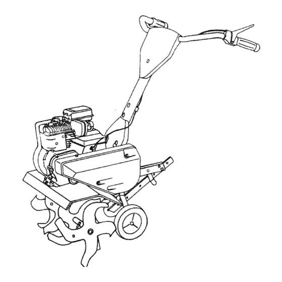
KNOW YOUR TILLER READ THIS OWNER'S MANUAL AND SAFETY RULES BEFORE OPERATING YOUR TILLER. Compare the illustrations with your tiller to familiarize yourself with the location of various controls and adjustments. Save this manual for future reference. These symbols may appear on your Tiller or in literature supplied with the product. Learn and understand their meaning. -
Page 9: Depth Stake
i ,i,_11 The operation of any tiller can result in foreign objects thrown into the eyes, which can result in severe eye damage. Always wear safety glasses or eye shields before starting your tiller and while tilling. We recommend a wide vision safety mask over the spectacles or standard safety glasses. -
Page 10: Starting
RATION to within i/2 inch of top TRANSPORTING YOUR TILLER of fuel tank to prevent spills and to allow for fuel expansion. If gasoline is ing, allow tiller engine and muffler accidentally spilled, move machine cool. Disconnectsparkplugwire. Drain away from area of spill. Avoid creating AUTION: Before lifting or transport- gasoline... -
Page 11: Cultivating
• OPERATION =,H= ,,,H= • You will find tilling much easier if you leave a row _----_ PARK untilled between passes. Then go back over the entire area at right angles (See Fig. 9), There are two reasons PLUG for doing this. First, wide turns are much easier to negotiate than about-faces. -
Page 12: Customer Responsibilities 3
......iiii 1111111 IIIMIIIII I IIIIII1'111I I I III II CUSTOMER RESPONSIBILITIES i,iiiii1,1,,i,iii ii ii MAINTENANCE SCHEDULE FiLL IN DATES AS YOU COMPLETE SERVICE DATES REGULAR SERVICE Check Engine Oil Leve_ .... Ill II Change Engine Oil _t,2 iiiiiiiNi i ii,llll Oil Pivot Points ,,,, ,,,,, ,., ,, inspect Spark Arrester Muffler... -
Page 13: Cooling System
CUSTOMER RESPONSIBILITIES accidental starting of engine. Prevent fires! Keep the engine free of grass, leaves, spilled oil, or fuel. Remove fuel from tank before tipping unit for maintenance. Clean muffler area of all grass, dirt, and debris. & Disconnect spark plug wire before performing any maintenance (except carburetor adjustment) to prevent Do not touch hot muffler or cylinder fins as contact may cause burns. -
Page 14: Handle Height
..===H'HH= CUSTOMER NSIBILITIES =1 = ,,=, MUFFLER TRANSMISSION Do not operate tiller without muffler. Do not tamper with Your transmission is sealed and wilt only require lubrication exhaust system. Damaged mufflers or spark arresters if it is serviced. could create a fire hazard. Inspect periodically and replace CLEANING if necessary. -
Page 15: Tines
D ADJUSTMENTS FINAL CHECK "ON" POSITION MID-WIDTH TILLING - 22 INCH PATH (See Fig. 17) Assemble holes "A" in tine hubs to holes "C" in tine • With fine control "ON" (held down to handle) push down shaft. on handle to raise tines off the ground. •... -
Page 16: V-Belt
,111111 ..... SERVICE AND ADJUSTMENTS ... : .........., ,i TO REMOVE BELT GUARD (See Fig. 20) TO REPLACE V-BELT (See Fig. 21) Remove cap nut and washer from side of belt guard, Repiace V-belt if it has stretched considerably or if it has cracks or frayed edges. - Page 17 InnnnHI,Hn'HHnl II,n SERVICE AND ADJUSTMENTS ENGINE THRorrLE U.KAGE T.ROW,E S TOP TO ADJUST CARBURETOR (See Fig. 22) The carburetor has a high speed fixed jet and has been preset at the factory and adjustment should not be neces- sary. However, minor adjustments may be required to compensate for differences in fue!, temperature, altitude or load.
-
Page 18: Storage
ENGINE Immediatefy prepare your tiller for storage at the end of the season or if the unit will not be used for 30 days or more. Drain oil (with engine warm) and replace with clean oil. (See ENGINE n the Customer Responsfbl Itsessection of CAUTION: Never store the tiller with this manual). -
Page 19: Troubleshooting
, i i, i ,11 ilnlnlnl i iii inll, ,Ulllll,lln Ulll TROUBLESHOOTING POINTS ii ii iiii Ullll PROBLEM CAUSE CORRECTION Will not start 1. Out of fuel. Fill fuel tank. 2. Eng{ne not"CHOKED" properly. 2. See "TO START ENGINE" in the Operation section. 3. -
Page 20: Repair Parts
REPAIR PARTS TILLER -- MODEL NUMBER 917,292360 HANDLE ASSEMBLY DESCRIPTION PART DESCRIPTION PART 73970500 STD533125 Locknut, Flange 5/16-18 UNC Bolt, Carriage 121145X 5/16-18 UNC x 2-1/2Grade 5 Clip, Cable 110514X 137118 Assembly, Panel and Tube Panel, Control 98000129 152094 Nut, Flange Assembly, Handle Column STD533107 9266R... -
Page 21: Repair Parts
REPAIR PARTS TILLER - - MODEL NUMBER 917.292360 BELT GUARD AND PULLEY ASSEMBLY PART DESCRIPTION DESCRIPTION PART Bracket, Bett Guard 121313X 12000036 Ring, Klip 9484R STD54t237 * Nut, Hex, Jam 3/8-16 Clip, Plated 86777 Screw, Hex #10-24 X ,50 9!78R Pulley, Idler 74770812 Bolt, Hex 1/2-20 x 3/4... -
Page 22: Repair Parts
REPAIR PARTS TILLER - - MODEL NUMBER 917.292360 WHEEL AND DEPTH STAKE ASSEMBLY <- DESCRIPTION PART DESCRIPTION PART 74760524 Bolt, Hex 5/16-18 x 1-1/2 Grade 2 Pin, Clevis 9194R 1951J Bolt, Hex Head 5/16-18 x 1-I/4 Support, Depth Stake, L.H. 74760520 120958X Washer... -
Page 23: Repair Parts
REPAIR PARTS TILLER - - MODEL NUMBER 917.292360 TINE ASSEMBLY PART DESCRIPTION PART DESCRIPTION 674A66 Tine, Outer, R.H. 674A63 Tine, Inner, L.H. Tine, Outer, L.H. STD624008 Clip, Hairpin 674A65 Tine, Inner, R.H. 4929H Pin, Clevis 674A64... -
Page 24: Type
REPAIR PARTS TILLER -- MODEL NUMBER 917.292360 TRANSMISSION PART DESCRIPTION PART DESCRIPTION 74760524 Boit, Hex 5/16-18 x 1-1/2 Grade 2 STD541431 Nut, Hex, Keps 5/16-18 UNC 19091412 74780652 Bolt, Fin, Hex 3/8-16 x 3-1/4 Washer 9/32 x 7/8 x t2 Gauge 19092016 STD551037 Washer 13/32 x 13/16 x 11... - Page 25 REPAIR PARTS TILLER - - MODEL NUMBER 917.292360 DECALS DESCRIPTION PART 158094 Decal, Logo 158093 Decal, Logo 158005 Decal, Logo 158006 Decal, 5HP/24 Sears 137539 Decal, Caution, Tine Control 120431X Decai, Hand Placement 110719X Decal, Operation and Lubrication 120075X Decal, Warning, Rotating Tines 272931 Decal, Engine 272630...
-
Page 26: Engine
REPAIR PARTS TILLER - - MODEL NUMBER 917,292360 BRIGGS & STRATTON ENGINE - - MODEL NUMBER 137202,TYPE NO. 0714-A1 40 529 IIHI... - Page 27 REPAIR PARTS TILLER - - MODEL NUMBER 917.292360 ENGINE - 137202,TYPE BRIGGS & STRATTON - MODEL NUMBER 0714-A1...
- Page 28 REPAIR PARTS TILLER - - MODEL NUMBER 917.292360 BRIGGS & STRATTON ENGINE - - MODEL NUMBER 137202, TYPE NO. 0714-A1 "k"REQUIRES SPECIAL TOOLS TO INSTALL. SEE REPAIR INSTRUCTION MANUAL.
- Page 29 REPAIR PARTS TILLER - - MODEL NUMBER 917.292360 BRIGGS & STRATTON ENGINE -- MODEL NUMBER !37202,TYPE NO. 0714-A1 KEY PART KEY PART NO. NO. DESCRIPTION NO. NO. DESCRIPTION 497144 Cylinder Assembly 93312 Retainer, Intake Valve and Exhaust 399268 Bushing, Cylinder Spring 299819 * Sea!, Oil...
-
Page 30: Engine
REPAIR PARTS TILLER = - MODEL NUMBER 917.292360 BRIGGS & STRATTON ENGINE - - MODEL NUMBER 137202,TYPE NO. 0714-A1 KEY PART KEY PART NO. NO. DESCRIPTION NO, NO. DESCRIPTION 202A 262470 Link, Control 94914 Screw, Sems, Tank Bracket Mount. 203 280720 Belt Crank 527 223786 Clamp, Breather Tube... - Page 31 NOTES...
-
Page 32: Replacement
£RIIFTSMAN ° OWNER'S 5.0 HP MANUAL 24 INCH TIN FRONT TINE TILLE MODEL NO. Each tiller has its own model number. Each engine has its own model number. 917.292360 The model number for your tiller will be found on a plate attached to the right hand engine bracket.