Table of Contents
Advertisement
Advertisement
Table of Contents

Related Manuals for Fujitsu Siemens Computers D1740


Summary of Contents for Fujitsu Siemens Computers D1740
- Page 1 answers Technical Manual Mainboard D1740 English...
- Page 2 ...des questions techniques ou des problèmes ? Veuillez contacter : Votre partenaire commercial Votre point de Vente Vous trouverez des informations actualisées sur nos produits, des conseils, des mises à jour, etc. sur notre site Internet : http://www.fujitsu-siemens.com ou http://www.fujitsu-siemens.com/mainboards...
- Page 4 Questo manuale è stato stampato su carta da riciclaggio. Denna handbok är tryckt på recyclingpapper. Dit handboek werd op recycling-papier gedrukt. Herausgegeben von/Published by Fujitsu Siemens Computers GmbH Bestell-Nr./Order No.: A26361-D1740-Z120-1-6319 Printed in the Federal Republic of Germany AG 0204...
- Page 5 Deutsch English Mainboard D1740 Français Technisches Handbuch Technical Manual Ausgabe April 2004 April 2004 edition...
- Page 6 Alle weiteren genannten Warenzeichen sind Warenzeichen oder eingetragene Warenzeichen der jeweiligen Inhaber und werden als geschützt anerkannt. Copyright ã Fujitsu Siemens Computers GmbH 2004 Alle Rechte vorbehalten, insbesondere (auch auszugsweise) die der Übersetzung, des Nachdrucks, der Wiedergabe durch Kopieren oder ähnliche Verfahren.
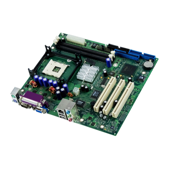
- Page 7 Übersicht/Overview Mainboard D1740 1 = Stromversorgung / Interne Anschlüsse und Steckplätze / Power Supply internal connectors and slots 2 = Bedienfeld / Frontpanel 3 = Diskettenlaufwerk / Floppy disk drive 4 = IDE-Laufwerke 3/4 / IDE-drives 3/4 5 = IDE-Laufwerke 1/2 / IDE-drives 1/2 6 = Batterie / Battery 7 = USB...
-
Page 9: Table Of Contents
Contents Übersicht/Overview Mainboard D1740 ...................1 Mainboard D1740..........................1 Notational conventions.......................1 Important notes ..........................2 Information about boards ......................2 List of features...........................3 Special technical features – special features ................4 Brief instructions on installing mainboard ..................6 Prior to installation ..........................6 Interfaces and connectors ......................8 External ports ............................8 Audio ports and audio configuration...................9 Internal ports and connectors ......................11... -
Page 11: Übersicht/Overview Mainboard D1740
Mainboard D1740 Mainboard D1740 Your mainboard is available in different configuration levels. Depending on the configuration chosen, some of the hardware components described may not be available on your mainboard. Additional information Information on the BIOS Setup and additional descriptions of the drivers are contained: in the readme files on your hard disk on the driver floppy disks included on the CD "Drivers &... -
Page 12: Important Notes
Important notes Important notes With the mainboard installed you must open the system to access the mainboard. How to dismantle and reassemble the system is described in the operating manual accompanying the system. Observe the safety notes in the operating manual of your system. Incorrect replacement of the lithium battery may lead to a risk of explosion. -
Page 13: List Of Features
- / - / - / - SmartCard Reader Support (USB / serial) - / - - / - Fujitsu Siemens Computers Keyboard Power Button Support Support for PSC FMB 1.0 Special onboard features Silent Fan / Silent Fan LT - / ü... -
Page 14: Special Technical Features - Special Features
List of features Internal ports (continued) D1740-A D1740-C CD / AUX audio input - / - - / 1 Front panel Audio (9-pin for headphone, microphone) FireWire™ * (9-Pin, Intel standard header) USB Ports* (2.0, ~480 MB/s) Serial Ports* (FIFO, 16550 compatible) Fan Connectors PSU** / CPU / AUX1 / AUX2 - / - / - / - - / 1 / - / -... - Page 15 USB Security is a BIOS function that offers protection against unauthorised access regardless of the operating system used. If USB Security is activated, the system can only be started, if the MemoryBird of Fujitsu Siemens Computers is connected to one of the existing USB-ports.
-
Page 16: Brief Instructions On Installing Mainboard
Prior to installation Brief instructions on installing mainboard If you have purchased a separate mainboard, you can install the mainboard in your system in accordance with the following brief instructions. The activities described here assume a basic knowledge of PCs and cannot be carried out by a layperson. -
Page 17: Driver Installation
Prior to installation ► Should no suitable connection field be provided in the case, then you must install the connection field (1) provided. Ensure the plate is aligned properly so that the connections are suitable for the mainboard later. ► Set the mainboard on the edge on which the connection field is located (2) and then insert the board in the... -
Page 18: Interfaces And Connectors
External ports Interfaces and connectors The positions of the interfaces and connectors are shown on page "Cover". The components and connectors marked are not necessarily present on the mainboard. External ports The positions of the external ports are shown on page "Cover". PS/2 keyboard port, purple PS/2 mouse port, green Parallel port/Printer, burgundy... -
Page 19: Audio Ports And Audio Configuration
External ports Audio ports and audio configuration Audio ports Blue Green Connecting loudspeakers The mainboard supports 2, 4 or 6-channel audio mode. For surround sound it is possible to connect up to 6 analogue speakers and use the digital S/PDIF output. Analogue 2-channel audio output With the 2-channel configuration the functions Line-In, Line-Out and MIC are available. -
Page 20: Audio Configuration
External ports Audio configuration The mainboard supports 2, 4 or 6-channel audio mode. For surround sound it is possible to connect up to 6 analogue speakers and use the digital S/PDIF output (see "Audio ports" section). Depending on the operating system used, the audio driver and additionally installed software, you can configure the audio properties. -
Page 21: Internal Ports And Connectors
Internal ports and connectors Graphics port - Supported screen resolutions Depending on the operating system used, the screen resolutions in the following table refer to the mainboard screen controller. If you are using an external screen controller, you will find details of supported screen resolutions in the operating manual or technical manual supplied with the controller. -
Page 22: Pin Assignment Of Internal Ports
Pin assignment of internal ports Pin assignment of internal ports The pin assignment of some internal connections is shown in English in the following. Some of the following connectors may be optional! Front panel Power On/Off Power On LED 1) 2) HD-LED Watch the poling of the LEDs. - Page 23 Pin assignment of internal ports Audio port front Signal Signal Micro input Analogue GND Micro bias Analogue VCC Right line output Right line return not connected Left line output Left line return If the audio front panel is not used, you must plug jumpers on pin pairs 5/6 and 9/10. USB - dual channel (internal or external via special wire) Signal...
-
Page 24: Power Supply
Pin assignment of internal ports Power supply ATX Signal Signal +3.3 V (P3V3P) +3,3 V (P3V3P) +3,3 V (P3V3P) -12 V (P12VN) +5 V (VCC) PS on (low asserted) +5 V (VCC) Powergood (high asserted) -5 V (P5VN) +5 V Auxiliary (VCC Aux) +5 V (VCC) +12 V (P12VP) +5 V (VCC) -
Page 25: Settings With Switches And Jumpers
Pin assignment of internal ports Settings with switches and jumpers Setting via control-panel plug connector Pin pair A inserted = Skipping system and BIOS Setup password Pin pair B inserted = System BIOS recovery Pin pair C inserted = factory setting Please pay attention on the exact position of the pin pairs! Skipping system and BIOS Setup password - pinpair A Pinpair A enables skipping the system and BIOS Setup password. -
Page 26: Add-On Modules / Upgrading
Intel Celeron with 400 or 533 MHz System Bus in the mPGA478 design. A current list of the processors supported by this mainboard is available on the Internet at: www.fujitsu-siemens.com/mainboards. Installing the processor with heat sink and fan (optional) ►... - Page 27 Installing and removing processors Mounting heat sink Be sure to use heat conducting material between the processor and the heat sink. If a heat conducting pad (rubber-like foil) is already applied to the heat sink, then use it. Otherwise you must apply a very thin layer of heat conducting paste.
-
Page 28: Upgrading Main Memory
128, 256, 512 or 1024 Mbyte for one socket A current list of the memory modules recommended for this mainboard is available on the Internet at: www.fujitsu-siemens.com/mainboards. At least one memory module must be installed. Memory modules with different memory capacities can be combined. -
Page 29: Adding Pci Cards
Adding PCI cards Removing a memory module ► Push the clips on the right and left of the memory slot outward (1). ► Pull the memory module out of the memory slot (2). Adding PCI cards Technical data: 32 bit / 33 MHz PCI slots 5 V and 3.3 V supply voltage 3.3 V auxiliary voltage PCI bus interrupts - Selecting correct PCI slot... -
Page 30: Replacing Lithium Battery
Adding PCI cards Multifunctional expansion cards or expansion cards with integrated PCI-PCI bridge: These expansion cards require up to four PCI interrupts: INT A, INT B, INT C, INT D. How many and which of these interrupts are used is specified in the documentation provided with the card. The assignment of the PCI interrupts to the PCI IRQ Lines is shown in the following table: Onboard controller PCI INT... - Page 31 Adding PCI cards The lithium battery holder exists in different designs that function in the same way. ► Press the locking lug in the direction of the arrow; the battery jumps somewhat out of the holder (1). ► Remove the battery (2). ►...
-
Page 32: Bios Update
BIOS update BIOS update When should a BIOS update be carried out? Fujitsu Siemens Computers makes new BIOS versions available to ensure compatibility to new operating systems, new software or new hardware. In addition, new BIOS functions can also be integrated. -
Page 33: Bios Recovery - Recovering System Bios
BIOS Recovery - Recovering System BIOS BIOS Recovery - Recovering System BIOS All BIOS settings are reset to the default values. ► Open the casing as described in the operating manual. ► Set the jumper for "Restore system BIOS" to ON. (see "Settings with switches and jumpers"... -
Page 34: Drivers
Drivers Safety for processor on Fujitsu Siemens Computers mainboards If the processor uses an old or incorrect microcode, error-free operation cannot be ensured. Fujitsu Siemens Computers has therefore implemented a function on its mainboards that interrupts the booting process if no suitable microcode is available for the installed processor. The output error message is Patch for installed CPU not loaded. -
Page 35: Annex
Mainboard current requirement You require a Pentium4 power supply nit as per the ATX12V specification for this mainboard. If you do not have a PC from Fujitsu Siemens Computers, make sure that the power supply unit provides the required amperages. -
Page 36: Apm And Acpi System Status, Energy-Saving Modes
APM and ACPI system status, energy-saving modes APM and ACPI system status, energy-saving modes System ACPI Power Power Sleep Power Wake-up status Status Status LED I LED II consum time ption Normal On/Off Normal operation Simple Standby Off/On flashin Almost Almost energy- like... -
Page 37: Mainboard Revision And Bios Version
The compatibility, e.g. with new processors, can be independent of the BIOS version or the revision status of the mainboard used. The CPU and BIOS compatibility lists are available on the Internet at www.fujitsu-siemens.de/mainboards. Mainboard: Revision level The revision status of the mainboard exactly identifies which mainboard you have. It is indicated on... -
Page 38: Error Messages
Available CPUs do not support the same bus frequency – System halted! Memory type mixing detected Non Fujitsu Siemens Memory Module detected – Warranty void There are more than 32 RDRAM devices in the system Check whether the system configuration has changed. If necessary, correct the settings. - Page 39 Error Messages DMA test failed EISA CMOS not writable Extended RAM Failed at offset: nnnn Extended RAM Failed at address line: nnnn Failing Bits: nnnn Fail-Safe Timer NMI failed Multiple-bit ECC error occurred Memory decreased in size Memory size found by POST differed from EISA CMOS Single-bit ECC error occurred Software NMI failed System memory exceeds the CPU’s caching limit...
- Page 40 Error Messages Missing or invalid NVRAM token Switch the device off and on again. If the message is still displayed, please contact your sales outlet or customer service centre. Monitor type does not match CMOS - RUN SETUP Correct the entry for the monitor type in the Main menu of the BIOS Setup. On Board PCI VGA not configured for Bus Master In the BIOS Setup, in the Advanced menu, submenu PCI Configuration, set the Shared PCI Master Assignment entry to VGA.
-
Page 41: Dos Error Messages
DOS error messages System battery is dead - Replace and run SETUP Replace the lithium battery on the mainboard and redo the settings in the BIOS Setup. System Cache Error - Cache disabled Switch the device off and on again. If the message is still displayed, please contact your sales outlet or customer service centre. -
Page 42: Smartcard Reader - Error Messages
SmartCard reader - error messages SmartCard reader - error messages This chapter contains error messages generated by the SmartCard reader (chipcard reader). Boot access denied The Sicrypt SmartCard has no access rights to the system. Check your chipcard Either the Sicrypt SmartCard has been wrongly inserted, or it is not a PC-Lock Sicrypt card. Chipcard reader FAIL An error has occurred on the serial port to the SmartCard reader (chipcard reader). -
Page 43: Glossary
Glossary Glossary The technical terms and abbreviations given below represent only a selection of the full list of common technical terms and abbreviations. Not all technical terms and abbreviations listed here are valid for the described mainboard. ACPI Advanced Configuration and Industrial Standard Architecture Power Management Interface AC'97...
Need help?
Do you have a question about the D1740 and is the answer not in the manual?
Questions and answers