Table of Contents
Advertisement
Quick Links
Operator's IVlanuai
CRRF r. MgN°
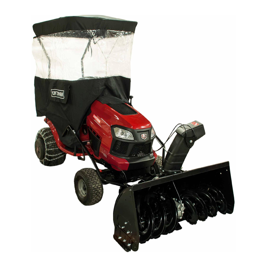
42"- 2 STAGE SNOW THROWER
TRACTOR ATTACHMENT
IVlodei No. 486.248371
DO NOT RETURN
TO STORE
For Missing Parts or Assembly
Questions
Call 1-866-576-8388
FITS HUSQVARNA
TRACTORS
AND CRAFTSMAN
TRACTORS WiTH MODEL
NUMBERS THAT BEGIN WiTH 917.
CAUTION:
Before using this product, read
this manual and follow all Safety
Rules and Operating
Instructions.
,, Safety
,, Assembly
,, Operation
,, Maintenance
,, Parts
Sears, Roebuck
and Co., Hoffman
Estates, IL 60179 U.S.A.
www.sears.com/craftsman
PRINTED IN U.S.A.
FORM NO. 42316 (06/15/11)
Advertisement
Table of Contents

Related Manuals for Craftsman 486.248371


Summary of Contents for Craftsman 486.248371
- Page 1 TRACTOR ATTACHMENT For Missing Parts or Assembly Questions Call 1-866-576-8388 IVlodei No. 486.248371 FITS HUSQVARNA TRACTORS AND CRAFTSMAN TRACTORS WiTH MODEL NUMBERS THAT BEGIN WiTH 917. CAUTION: ,, Safety Before using this product, read ,, Assembly this manual and follow all Safety...
-
Page 2: One Year Full Warranty
Sears, Roebuck and Co., D817WA, Hoffman Estates, IL 60179 These and other accessories are recommended for use with your unit. Call 1-800-4-MY-HOME® to find out if they are available. If available, they may be purchased at most Craftsman outlets or by calling 1-800-4-MY-HOME®. WHEEL WEIGHT... -
Page 3: Accessories
Read andunderstand theoperating instructions before using. Keep the area of operation clear of all persons, especially small children and pets. Thoroughly inspect the area to be cleared and remove all door mats, sleds, boards, wires and other foreign objects. Use extreme caution when operating on or crossing gravel surfaces. - Page 4 SHOWN ACTUAL SIZE r--qq ..43182 43063 43661 43840 43351 43020 43084 • JL 49933 48106 46938 43350 43O80 43682 710-0890A 44215 . W,X R19171616 43088 _ .... 47630 43081 47605, 43070 49948 47631 _\\\\\\ 27231 43003 43086 44695 R19172410 46584 47598 43082...
-
Page 5: Actual Size
NOT SHOWN ACTUAL SiZE 46959 731-0851A 711-0198 47134 43343 [__z 43055 23727 714-04061 1643-60 43038 z XX j WW 726-0178 47788 46963 IMPORTANT: Not all items supplied in the hardware bag will be needed for your particular tractor. Unneeded items may be discarded after you have completed assembly and checked operation of unit. - Page 6 19. R.H.Hanger B racket (Inside Mounting) 20. LeftHand SidePlate ClutchIdlerAssembly 10. RearPulley Frame Bracket (2) 21. RightHandSidePlate 11. Anti-rotation B racket. 22. Pulley 23. Spacer, 3/8" ONLY iTEMS NEEDED FOR CRAFTSMAN MODEL 917 TRACTORS AND HUSQVARNA TRACTORS ARE SHOWN 24558 47043 24394 25728...
- Page 7 Skip to "TOOLS REQUIRED FOR ASSEMBLY" set the parking brake and remove the key from the tractor ignition. IFYOU HAVE A CRAFTSMAN TRACTOR TRACTOR PREPARATION LOCATE THE MODEL LABEL Look under the tractor seat to locate the model number Before performing these instructions, refer to the Service label.
- Page 8 IDENTIFYYOUR TRACTOR iNSTALL SIDE PLATES STEP 3: (SEE FIGURE 3) STEP 1: (SEE FIGURE 1) Fasten the R.H. Side Plate (bend facing out) to the Look under the front of your tractor. If there is a single front three holes in the tractor frame using three 3/8" mower deck suspension bracket located underneath x 1"...
-
Page 9: Left Side View
iNSTALL HANGER BRACKETS AND SHOULDER BOLTSTO OUTSIDE OF FRAME STEP 5: (SEE FIGURE 5) Remove the bolt, if present, in the hole directly behind the brake rod on the left side of the tractor frame. Attach the L.H. Hanger Bracket (tube facing out) to the hole using a 5/16"... - Page 10 THIS SECTION IS FOR TRACTORS WITH A STEP 9: (SEE FIGURE 9) MAN UAL ATTACHM ENT CLUTCH Attach each rear pulley frame bracket to the inside of the clutch/idler assembly using two 5/16" x 3/4" hex if your tractor has an electric attachment clutch go to bolts, 5/16"...
- Page 11 STEP11: (SEEFIGURE 11) PIVOT LOCK PiN 1/8" HAiRPiN NYLON TiE Find the cable clip that is attached to the left side (use this hole) COTTER of the tractor frame underneath the footrest. Open the clip and remove the mower clutch cable. Do not L.H.
- Page 12 THIS SECTION IS FOR TRACTORS WITH AN STEP 18: (SEE FIGURE 16) ELECTRIC ATTACHMENT CLUTCH Attach each rear pulley frame bracket to the inside of the clutch/idler assembly using two 5/16" x 3/4" hex STEP 14: (SEE FIGURE 14) bolts, 5/16" washers and 5/16" nylock nuts. •...
- Page 13 STEP 18: (SEE FIGURE 17) STEP 20: (SEE FIGURE 19) Turn the clutch/idler assembly right side up. Assemble the drive belt onto the engine pulley first Slightly loosen the hex bolt next to the flat idler pulley. and then onto the large pulley on top of the clutch/ Install the drive belt down between the hex bolt and the idler assembly.
- Page 14 iNSTRUCTiONS FOR TRACTORS WITH DUAL STEP 23: (SEE FIGURE 22) FRONT DECK SUSPENSION BRACKETS Remove any bolts found in the holes shown. REMOVE BOLTS FASTEN SIDE PLATES TO TRACTOR IF PRESENT if your tractor resembles figure 20, go to step 21. If your tractor resembles figure 22, go to step 23.
- Page 15 INSTALLING SHOULDER BOLTS iNSTALLiNG HANGER BRACKETS For better clearance, lower the tractor's suspension arms STEP 27: (SEE FIGURE 27) using the attachment lift lever. Remove the bolt, washer and nut which fasten the sway bar bracket to the L.H. side of the tractor frame. STEP 26: (SEE FIGURE 25 or 26) Replace with a shoulder bolt and a 3/8"...
- Page 16 iNSTALLiNG CLUTCH/IDLER ASSEMBLY Attach the two front pulley frame brackets to the inside This section covers the installation of the Clutch/Idler of the clutch/idler assembly using two 5/16" x 3/4" hex bolts, 5/16" washers and 5/16" nylock nuts for each assembly to tractors with attachment clutches that are bracket.
- Page 17 STEP32: (SEEFIGURE 32) NEW ENGINE PULLEY KEEPER WiTH • Besuretoliftupthefrontendoftheengagement rod ORiGiNAL BOLT, NUT AND WASHER asshown whenperforming t henextoperation. You cantemporarily support t herodusing a rubber b and tiedtotheengine pulleykeeper. Attach theclutch/idler assembly t othetractor f rame TRUNNION asfollows. Hooktheassembly's n otched rearpulley frame brackets o ntothetwoshoulder b oltsyou assembled to theinside ofthetractor f rame.
- Page 18 CABLEOPERATED M ANUAL ATTACHMENT CLUTCH STEP 37: (SEE FIGURE 37) Three different length drive belts are included with your snow thrower. Tractors with manual attachment STEP 35: (SEE FIGURE 35) Assemble the cable bracket to the inner half of the clutches and dual front deck suspension brackets use the 55"...
- Page 19 STEP38: (SEEFIGURE 38) NEW ENGINE PULLEY KEEPER WiTH • Move theattachment clutchlever o nthedashpanel t o ORiGiNAL BOLT, NUT AND WASHER thedisengaged (down) p osition. Place theclutch/idler assembly o nthefloorontheright PIVOT LOCK PiN sideofthetractor. use second hole) Attach thetractor's c lutch cable tothecable bracket. 1/8"...
- Page 20 ELECTRIC ATTACHMENT CLUTCHES STEP 43: (SEE FIGURE 43) Attach the two rear pulley frame brackets to the inside of the clutch/idler assembly using two 5/16" x 1" hex STEP41: (SEEFIGURE 41) bolts, eight 5/16" washers and two 5/16" nylock nuts •...
- Page 21 STEP 45: (SEE FIGURE 44) STEP 47: (SEE FIGURE 46) Turn the clutch/idler assembly right side up. • Assemble the drive belt onto the engine pulley and Slightly loosen the hex bolt next to the flat idler pulley. then onto the large pulley on top of the clutch/idler Install the drive belt down between the hex bolt and the assembly.
- Page 22 ASSEMBLY OF THE SNOW THROWER STEP 50: (SEE FIGURE 49) Tilt the snow thrower back down to the ground. STEP 48: (SEE FIGURE 47) Remove the nylon tie which fastens the auger • Place the lift handle into the lift bracket on the right side drive belt to the discharge housing, leaving the belt of the snow thrower.
- Page 23 STEP52: (SEEFIGURE 51) STEP 53: (SEE FIGURE 52) • Attach thechutecrankrodassembly b rackets t o Coat the top of the ring around the discharge opening theplasticbracket o nthe leftsideofthedischarge with general purpose grease. housing. Alignthechutecrankbracket b eneath the Place the discharge chute (facing forward) onto the rodsupport b racket a ndassemble b othtotheplastic ring.
-
Page 24: Belt Routing Diagram
iNSTALLiNG THE AUGER BELT ATTACHING SNOW THROWER TO TRACTOR STEP 57: (SEE FIGURE 56) Push the lift handle down to increase slack in the belt 55: (SEE FIGURE 54) • Place the snow thrower on a flat, level surface. (attachment pin must first be removed). Extend the auger belt out behind the snow thrower, Swing the idler arm over to the side. - Page 25 INSTALLING THE ATTACHMENT ATTACH REFLECTORS TO REAR FENDER STEP 60: (SEE FIGURE 58) STEP 58: (REFER BACKTO FIGURE 54 ON PAGE 24) if your tractor is not equipped with rear reflectors, Lift the front of the snow blower to align the holes in assemble the supplied rear reflectors to the rear fender.
-
Page 26: Safety Rules
KNOW YOU R SNOW TH ROWER Read this owner's manual and safety rules before operating your snow thrower. Compare the illustration below with your snow thrower to familiarize yourself with the various controls and their locations. LIFT RELEASE TRIGGER CHUTETI_ HANDLE LIFT HANDLE •... -
Page 27: Raising Andlowering
RAISING ANDLOWERING Inextremely d eepsnow, r aisethesnowthrower f rom theground to remove thetoplayeranddriveforward • Toraise, p ushdownonthelifthandle untilthesnow onlyuntil t hetractors fronttiresreach theuncleared thrower l ocksintheraised transport p osition. bottom layerofsnow. D epress thetractor's clutch- Tolower, p ushdown slightly onthelifthandle andpull brakepedal a ndallowthespiral a uger toclearthe thetrigger. - Page 28 CAUTION: Before servicing oradjusting LiFT RELEASE CABLE ADJUSTMENT thesnow thrower, shut o fftheengine, r emove If the lift rod does not lock the snow thrower securely thespark plug wire(s), settheparking b rake in the transport position, loosen the upper hex nut on andremove t hekey from thetractor i gnition.
-
Page 29: Storage
STORAGE RECOMMENDATIONS PARTS TO REMOVE AT END OF SEASON • Lower the snow thrower to the ground. Remove the snow thrower from the tractor. Remove the clutch/idler assembly. (The two hanger Clean the snow thrower thoroughly. Wash off any salt brackets and the two shoulder bolts may be left deposit which may have dried on the thrower and attached to the tractor frame.) - Page 30 REPAIR PARTS FOR MODEL 488.248371 42" SNOW THROWER (For Husqvarna Tractors And Craftsman Series 917 Tractors) 4 tz, 67" 537O 18 41 65 21 40, 59 40, 59 _¢_ 54 _...
- Page 31 REPAIR PARTS FOR MODEL 488.248371 42" SNOW THROWER (For Husqvarna Tractors And Craftsman Series 917 Tractors) PART NO DESCRIPTION PART NO DESCRIPTION 05931 27280 Housing, Bearing Bracket, Idler 65701 49933 Housing Assembly Shoulder Bolt, Round Head 71464 65367 Gear Assembly Hanger Bracket Assembly, L.H.
- Page 32 REPAIR PARTS FOR MODEL 488.248371 42" SNOW THROWER (For Husqvarna Tractors And Craftsman Series 917 Tractors) 65 58 60 !6 !6 35._. 59--_ C...
- Page 33 REPAIR PARTS FOR MODEL 486.248371 42" SNOW THROWER (For Husqvarna Tractors And Craftsman Series 917 Tractors) PART NO DESCRIPTION PART NO DESCRIPTION 64637 Bracket, Chute Crank Lift Shaft Assembly 703-2735A 710-0865 Hex Bolt, 1/2-13 x 1" 720-0201A Knob, Crank 710-0367 Hex Bolt, 5/8-11 x 1-1/2"...
- Page 34 REPAIR PARTS FOR MODEL 488.248371 42" SNOW THROWER (For Husqvarna Tractors And Craftsman Series 917 Tractors) PART NO DESCRiPTiON 43082 Nut, Hex Lock, 3/8-16 46982 Pulley, VType 5-1/2" 738-0680 Shaft 750-0456 Spacer 750-0660 Spacer 43003 Lock Washer, 3/8" 714-0161 45--..._...
- Page 35 SUGGESTED GUIDE FOR SIGHTING SLOPES FOR SAFE OPERATION OF TRACTOR WITH ATTACHMENT _FOLD ALONG THISISA - OTTED LINE ONLY RIDE UP AND DOWN HILL, NOT ACROSS HILL 10 DEGREES MAX. WARNING: To avoid serious injury, operate your tractor up and down the face of slopes, never across the face.
-
Page 36: Troubleshooting
Your Home For expert troubleshooting and home solutions advice: www.managemyhome.com For repair - in your home - of all major brand appliances, lawn and garden equipment, or heating and cooling systems, no matter who made it, no matter who sold it! For the replacement parts, accessories owner's manuals that you need to do-it-yourself.