Table of Contents
Advertisement
Quick Links
Download this manual
See also:
Quick Reference Manual
Advertisement
Table of Contents

Related Manuals for EverFocus EPHD08


Summary of Contents for EverFocus EPHD08
- Page 1 User Manual 8 channel HD-CCTV Digital Video Recorder...
- Page 2 All rights reserved. No part of the contents of this manual may be reproduced or transmitted in any form or by any means without written permission of the Everfocus Electronics Corporation. Release Date: Nov. 2010 QuickTime is a registered trademark of the Apple Computer, Inc.
- Page 3 Safety Precautions Refer all work related to the installation of this product to qualified service personnel or system installers. Do not block the ventilation openings or slots on the cover. Do not drop metallic parts through slots. This could permanently damage the appliance. Turn the power off immediately and contact qualified service personnel for service.
- Page 4 Unplug the unit from the outlet before cleaning. Do not use liquid cleaners, abrasive or aerosol cleaners. Use a damp cloth for cleaning Attachments Do not use attachments not recommended by the product manufacturer as they may cause hazards. Water and Moisture ...
- Page 5 WEEE This Product is RoHS compliant. The information in this manual was current upon publication. The manufacturer reserves the right to revise and improve his products. Therefore, all specifications are subject to change without prior notice. Manufacturer is not responsible for misprints or typographical errors.
-
Page 6: Table Of Contents
TABLE OF CONTENTS PRODUCT OVERVIEW ..................... 1 FEATURES ........................1 PACKAGE CONTENTS....................2 SPECIFICATIONS ......................3 FRONT PANEL ........................ 4 REAR PANEL........................6 INSTALLATION........................8 HD-CCTV ................8 WIRING FOR VIDEO INPUTS 2.1.1 Understanding HD-CCTV signals and wiring ..................8 2.1.2 HD-CCTV signal .............................8 2.1.3 Cable types ..............................9... - Page 7 2.2.3 Front Panel Key Review........................22 2.2.4 Operation in Configuration Menu......................22 2.2.5 Field Input Options ..........................23 GENERAL DVR OPERATIONS..................25 RECORD ......................... 25 LOGIN..........................25 SELECT CAMERA OPERATION................. 26 PLAYBACK........................27 PTZ ..........................28 General PTZ control (if PTZ cameras are installed)..................28 3.6.1 3.6.2 Express Control of PTZ.........................29...
- Page 8 6.2.2 Enabling ActiveX Controls ........................113 REMOTE LIVE VIEW ....................116 REMOTE PLAYBACK ....................118 EVERFOCUS DDNS SETUP ..................119 LINKSYS & D-LINK PORT FORWARDING ............. 121 TYPICAL LINKSYS PORT FORWARDING ............. 121 TYPICAL D-LINK PORT FORWARDING ..............123 TROUBLESHOOTING ....................126 APPENDIX A: TIMING OF ALARM MODES..............
-
Page 9: Product Overview
IP addresses. Or, make the transition from SD/D1 to Full HD as easy as attaching new EverFocus HD-CCTV cameras to the existing coax and power, and upgrading the DVR to the EPHD08 HD DVR. The Paragon HD DVR and HD- CCTV cameras provide tremendous advances in resolution over traditional analog CCTV cameras. -
Page 10: Package Contents
3 USB2.0 ports for video archive and mouse usage Multi –language support 19” rack mountable – rack ears included 1.2 PACKAGE CONTENTS HDD fixing bracket x 4 (Internal HDD model) DVR fixing bracket x 2 ... -
Page 11: Specifications
130W max. with 4 x HDD Dimensions (L x W x H) 410 x 430 x 88 mm / 16.2" x 16.9" x 3.5" Temperature 0°C~40°C / 32°F~104°F (20~80% humidity) EverFocus, Pelco D, Pelco P, Samsung, Transparent Supported PTZ Protocols... -
Page 12: Front Panel
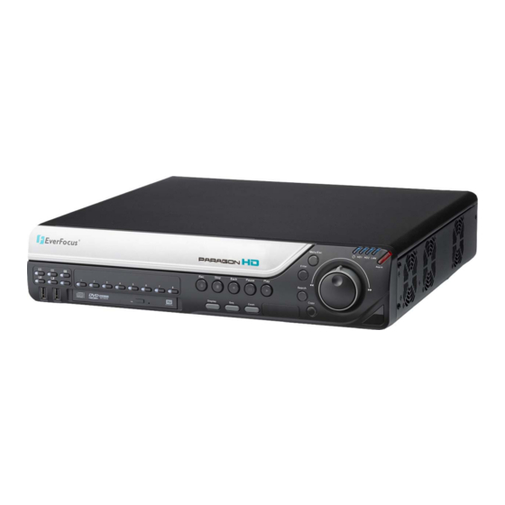
1.4 FRONT PANEL Your primary interaction with your new DVR will be through the Front Panel buttons and their corresponding buttons on the included IR Remote Control. Take a moment to learn where the keys are as the remainder of the manual will refer to them often. Figure 1-1 Front Panel 2 x USB-2.0 port for USB mouse, USB-Flash-Drive Multiview Keys:... - Page 13 Record: RECORD key for manual start of recording / recording standby (event recording). LED will be ON if DVR is recording or in record standby. STOP: STOP key for Playback and Record BACK: Reverse Playback key PAUSE: Image freeze in playback mode PLAY: Playback key ENTER: Enter Key for menu operation and alarm acknowledge Turn camera audio ON/OFF when viewing full screen camera.
-
Page 14: Rear Panel
1.5 REAR PANEL During initial setup you will be connecting your DVR to multiple input and output devices. This is done through the rear panel. Figure 1-2 Rear Panel POWER: Power input 100~240 VAC. ○ eSATA port: Used for external SATA HDD bay ○... - Page 15 HDMI Out: Provides an uncompressed all-digital video interface between the HD DVR and HDMI- ○ compatible monitor. HDMI output format is 1920x1080p 60Hz vertical, 68 KHz horizontal. VGA Out: Connect a VGA monitor to the VGA output connection. DVR can auto detect the best ○...
-
Page 16: Installation
2.1 HD-CCTV wiring for video inputs 2.1.1 Understanding HD-CCTV signals and wiring Even if EverFocus HD-CCTV equipment uses coaxial cable and BNC type plugs similar to standard CCTV technology - the requirements for wiring and cable types are some different. -
Page 17: Cable Types
The standard RG-59 cable types - the most common in the CCTV industry - are originally designed for lower frequencies. However, due to the new optimized receiver interfaces of EverFocus HD-CCTV equipment it is also possible to use standard RG-59 cable for distances of over 100m. -
Page 18: Cable Installation
2.1.4 Cable installation Please make sure, that the coaxial cable is not squeezed at any position. Also the max. bending radius defined by the cable manufacturer should be considered. General rule: maximum bending radius = 10 x outer cable diameter Bending creates pressure on the center conductor, causing it to move through the dielectric toward the inside of the bend. -
Page 19: Extended Cable Lengths With Fiber Optics Transmission
2.1.7 Extended cable lengths with fiber optics transmission The maximum distance between camera and receiving device can be extended by fiber optics cable. The transmitters and receivers are available for multi-mode and single-mode fiber cables: EHA-FTX-MM: Fiber optics transmitter multi-mode, max. transmission distance 500 m EHA-FTX-SM: Fiber optics transmitter single-mode, max. -
Page 20: Monitor Installation
2.1.8 Monitor installation The EPHD-8 provides 2 main monitor outputs with identical functionality - VGA and HDMI. Both outputs can be used simultaneously and deliver full HD output resolution ( 1920x1080, progressive, 60 Hz. vert., 68 KHz hor.). Make sure that the connected monitor's specifications comply with these resolution requirements. Please do not exceed the max. -
Page 21: Audio Installation
2.2 AUDIO INSTALLATION This DVR provides 8 line level audio input and 1 line level audio output. ATTENTION: The direct connection of a non-amplified microphone is not supported (a microphone amplifier is required). The audio output requires an amplifier to drive a speaker or headphones. The installation must be connected with audio coax cable and RCA plugs. -
Page 22: Keyboard / Ptz Installation
Cable length from box to device („Stubs“) has to be limited to 2m using connector boxes. RS-485 bus serial wiring with connector boxes and connection cable Direct RS-485 bus star wiring is not supported unless using an EverFocus Model EDA997A (see below). Improper RS-485 bus star wiring... - Page 23 An EDA997A RS-485 signal distributor may be used to use a star wiring configuration. Star wiring with RS-485 signal distributor A RS-485 distributor can also be used to increase the maximum number of devices on the bus as well as the total range.
-
Page 24: Socket Pin Assignment
PowerCon software if the DVR is connected to a network. Local telemetry control is provided by USB - mouse control or by the optional EKB-500 keyboard. Supported protocols: EverFocus, Pelco-D, Pelco-P, Samsung, Transparent Required DVR settings: RS-485 receiver address in CAMERA menu (Section 4.3.2) -
Page 25: Usb-Mouse Installation
2.5 USB-Mouse installation Connect the USB mouse to one of the 2 USB ports. (This can be done while DVR is powered on) NOTE: Recommended mouse types are Logitech® and Microsoft® wired USB wheel-mouse. Wireless USB mouse is not supported. 2.6 NETWORK CONNECTION This section only describes physical connection to an Ethernet network. -
Page 26: Network Connection Through Patch Cable
2.6.2 Network Connection through Patch Cable The connection to an existing network requires a normal patch cable (straight-through). The illustration shows the connection to a network switch or router. Figure 2-2 Network Connection through Patch Cable Pinout of straight patch cable 2.7 FINAL INSTALL PROCESS Once you have completed the basic wiring connections, you are ready to turn on the DVR. -
Page 27: Mouse And Front Panel Operation
Chapter 3 MOUSE AND FRONT PANEL OPERATION EPHD08 DVRs support multiple sources to control the DVR. It can be controlled with a mouse, the front panel, an EKB500, and the handheld IR remote control. This chapter will cover the basic operation using the mouse and the front panel buttons. 3.1 GENERAL USB MOUSE OPERATION 3.1.1 How to select a channel / Enable audio 1. -
Page 28: Operation In The Configuration Menus
3.1.3 Operation in the Configuration Menus Click on the icon to access the Configuration Menu. The Configuration menu screens (shown in Figure 3-2 OSD Menu) are divided into 3 main sections. Figure 3-2 OSD Menu 1. In section 1, there are ten setup options available. Move the mouse over an icon and click to select it. 2. - Page 29 Bar: Click and hold on the bar to adjust the set point Left or Right. * Note about on-screen keyboard: Click on a button to input that character. The buttons on the right and bottom have the following functions: Space Enter a space Caps Switch to capital letters...
-
Page 30: General Front Panel Operation
2.2 General Front Panel Operation 2.2.1 How to select a channel / Enable audio 1. In a view consisting of more than one channel, dial the jog/shuttle clockwise or counterclockwise to scroll through each channel that is displayed. The selected channel will be highlighted by white frame. Dial the jog/shuttle clockwise or counterclockwise when the last/first camera is highlighted will select all cameras. -
Page 31: Field Input Options
Figure 3-3 OSD Menu 1. In section 1, there are ten setup options available. Use the jog/shuttle to highlight an icon and press “Enter” to select it. 2. In section 2, the main choices for the selected icon will be displayed. Use the jog/shuttle to highlight a choice and press “Enter”... - Page 32 Bar: Press “Enter” key to activate the slider, then use the jog/shuttle to adjust the setting. Press “Enter” again to finalize the changes. * Note about on-screen keyboard: Use the jog/shuttle to highlight each character and press the “Enter” key on the front panel to input the selected characters.
-
Page 33: General Dvr Operations
Chapter 3. GENERAL DVR OPERATIONS This chapter introduces the operations on major functions including playback, layout change, sequence, triplex operations, copy, and search. 3.1 RECORD By default, the DVR will always be in record mode. When the DVR is turned on, it will start to record. The exceptions are: 1. -
Page 34: Select Camera Operation
+ To input password by mouse: click the password field to bring up the on-screen keyboard (see Figure 3-2 On-screen Keyboard). Click on each button to input the desired characters for the password. When finished, click “Done” on the on-screen keyboard to confirm the password. + To input password using front panel: use the jog/shuttle to select the password field, then press the “Enter”... -
Page 35: Playback
3.5 PLAYBACK The playback bar is the fastest way to show video from the exact time which users want to see. The playback bar allows a user to see both a time line and the current playback indicator. The user can then click the time line to move the indicator to the position which they want to see. -
Page 36: Ptz
Click “Preset” button b. Click the number of the desired position c. Click “Delete” button 9. For Auto Pan a. Click “Auto Pan” button 10. Pattern Operation (Pattern is the “0” Tour in Everfocus and Pelco PTZ cameras) a. Click “Pattern” button... -
Page 37: Express Control Of Ptz
11. Steps to run a tour a. Click “Tour” button b. Click the number of the desired tour c. Click “Go” button 12. Steps to remove a tour (if supported by the camera) a. Click “Tour” button b. Click the number of the desired tour c. - Page 38 Figure 3-3 Express Control PTZ The screen is divided into a 4x4 grid. The function of each section is defined as below: 1: PTZ pan/tilt left and up 2, 3: PTZ tilt up 4: PTZ pan/tilt right and up ...
-
Page 39: Layout
3.7 LAYOUT The EPHD08 DVR has several display modes available, depending on the number of cameras the DVR supports. The different available layouts for EPHD08 DVR are shown below: NOTE: PIP display is not available in Playback mode To change layout, follow the steps below: By mouse: Right-click to bring up the menu bar and click then click on the desired layout choice. -
Page 40: Display
3.9 DISPLAY Press the Display button on the menu by using the mouse or selecting this icon with the front panel keys and pressing ‘Enter’. Pressing/clicking cycles through the four OSD formats: 1. Press to show camera information. Please see the following table for camera information icons. Recording Playback Fast forward... -
Page 41: Search
4. When in ZOOM mode, the mouse cursor will change to a different icon in different areas of the screen. Or, use the jog/shuttle to bring a different portion of the magnified image into view. Users can control the portion of the magnified image to be displayed by clicking directly on screen: Figure 3-4 Zoom Express Control The screen is divided into a 4x4 grid. -
Page 42: Time Search
3.12.1 Time Search Figure 3-5 Search Menu – Time Search Play From: Select the time to begin the search by choosing the Date and Time. Click on the “Play” button to start the search. The DVR will automatically begin to play the video selected. The DVR will play the nearest time if there is no data at the selected time. -
Page 43: Event Search
3.12.2 Event Search Figure 3-6 Search Menu – Event Search From: Select starting date and time To: Select ending date and time. Camera: Select which cameras to include in the search. Event: Select which event type(s) to search for. Choose from Alarm, Motion or Video Loss. Click on the “Search”... -
Page 44: Smart Search
Prev Page: Go to previous page Next Page: Go to next page Play: Playback selected item Copy: Copy selected item 3.12.3 Smart Search Smart Search allows the review of a segment of the recorded video from individual cameras to detect motion in an area specified at the time of the search. - Page 45 Grid Setting: Press Grid Setting button to open the motion grid setup window. Edit Motion Grid: Press this button to edit the motion grid (See Figure 4-5 Camera Menu – Motion Grid Setting ). Set All: Press this button to select the entire area. Clear All: Press this button to clear all the grids selected.
- Page 46 Click on the “Search” button to start searching. The search results will be shown as a list of events. Prev Page: Go to previous page Next Page: Go to next page Play: Playback selected item Copy: Copy selected item...
-
Page 47: Copy
3.13 COPY To bring up Copy menu: By mouse: Right-click to bring up the menu bar and click on to enter Copy Menu. By front panel: Press the “Copy” key to enter Copy Menu directly. Figure 3-9 Copy Menu Camera: Select which cameras will be archived. Choose “Select All” to select all the cameras. Player: Check the box to include the ePlayer program as part of the copy (recommended). - Page 48 Figure 3-10 Logout Confirmation window Press “Yes” button when you are ready to logout from the system. You will need to login again before accessing any other configuration options.
-
Page 49: Dvr Configuration
Chapter 4 DVR CONFIGURATION This chapter will walk you through the DVR Menu Settings step by step and show you how to set the DVR for your specific application. 4.1 CONFIGURATION MENU 1. To bring up the Main Menu, press the “Menu” key on the front panel or right-click with the USB mouse to bring up the OSD menu bar. - Page 50 Date: Sets the current date of DVR. Time: Sets the current time of DVR. Record Mode: Choose from Normal+Event: Normal recording plus event recording. Event Only: Event recording only. Schedule Rec: Schedule recording. For Event recording, enter the estimated number of hours per day for event recording. Resolution: Recording resolution is displayed only.
- Page 51 DHCP: DHCP server in LAN will automatically assign IP for network connection. PPPoE: This is for direct DSL connection application ONLY (no router). Check with your ISP to see if they use PPPoE. IP Address: This field shows the current IP Address for the DVR. If Fixed IP address is used then this value must be set manually.
-
Page 52: Camera Setting
4.3 CAMERA SETTING Figure 4-2 is a screenshot of the CAMERA SETTING MENU. This menu is used to configure individual camera settings. Figure 4-2 Camera Menu-Global Setting 4.3.1 Global Setting Resolution: Select recording resolution. Choices are: 1920x1080 / 1280x720. The resolution setting is global, so a change of DVR´s resolution setting requires changing all camera´s resolution. -
Page 53: Basic Setting
4.3.2 Basic Setting Figure 4-3 Camera Menu-Basic Setting Camera: Select the camera to be configured. Title: The title setting allows you to assign a title to the selected camera. Each title supports up to 16 characters. The on-screen keyboard will appear when you click the title option. Install: Check the box to enable the current camera. - Page 54 PAL); Choices for possible record speeds are 30, 15, 10, 7.5, 5, 3, 2 and 1 FPS. Since EverFocus DVRs have the capability to change FPS rate in response to events, it may be advisable to reserve some recording capacity for event response.
-
Page 55: Motion
4.3.3 Motion Figure 4-4 Camera Menu – Motion Camera: Select the camera you wish to configure. “Title” will change to the title name of the selected camera. Enable: Check box to enable motion detection. Other motion options will not be available unless this feature is selected. - Page 56 Alarm Output: This will transmit a signal through the alarm output relay. It can be set to either “NONE” (not active), “1” or “2” (indicating which alarm relay is active). Output Type: Output action when motion is triggered. Timeout: Alarm output lasts for a set of time duration. If this option is selected, a field will appear for setting the duration.
- Page 57 5. Press Enter key at the starting point. 6. Use arrow keys to select motion area; the shape of the proposed area will be displayed. 7. Press Enter key at the end point, and the area will be selected. 8. Press the Menu key to exit the area selection; use the up/down arrows to choose “Save & Back”...
-
Page 58: Video Loss
4.3.5 Video Loss Figure 4-6 Camera Menu – Video Loss Camera: Select the camera you wish to configure, “Title” will change to the title name of the selected camera. Enable: Check box to enable Video Loss detection. Log: Check box to record video loss events in the log. Pre-alarm Record: Check box to start copying recorded video to the hard disk from 5 seconds before the video loss. -
Page 59: Record & Play Setting
Trans+Timeout: Alarm output continues until the event ends, then continues for a set time duration. Apply To: This button can be used to copy the video loss settings to other cameras. Select which cameras you wish to copy to. "Select All" selects all cameras, “Unselect All” deselects all cameras. Click “OK” to copy the settings or "Cancel"... -
Page 60: Play
Schedule Record: Use schedule recording mode. For Schedule recording, the only way to stop the DVR from recording is to turn schedule recording off. Pressing any key on the front panel to attempt to stop recording will not work during scheduling record mode. -
Page 61: Alarm & Event Setting
4.5 ALARM & EVENT SETTING Figure 4-4 is a screenshot of the ALARM & EVENT SETTING MENU. This menu will guide you through alarm and event setup. Figure 4-4 Alarm & Event Menu - Alarm 4.5.1 Alarm Alarm: Select the alarm input trigger connection number from 1 to 8 (one trigger per camera input). Enable: Check box to enable response to that alarm trigger. - Page 62 N.O.: Normal Open contact. N.C.: Normal Closed contact. Network Alarm: Check this box to send out a network alarm to a client PC when motion occurs. (This feature requires PowerCon software on the client PC and proper settings for the Alarm Server in the Network Setup menu;...
-
Page 63: Event
4.5.5 Event This section covers notifications due to internal system event warnings. Figure 4-5 Alarm & Event Menu – Event Event: Select from the following event types. Fan Failure: Fan is not working. HD Temperature: Hard drive is over the safety warning temperature. HD Failure: If DVR fails to detect the HDD on start up, the system will create an HD failure event. - Page 64 Fan Failure: Figure 4-12 Alarm & Event Menu – Event – Fan Failure Log: Check box to record fan failure events in the log. Buzzer: Check box to enable buzzer when fan is not working. Email Notify: Check box to enable email notification when fan is not working. Email operation requires that valid email settings have been entered in the Network Setting/Email setup screen.
- Page 65 HD Temperature: Figure 4-13 Alarm & Event Menu – Event - HD Temperature Log: Check box to record HDD temperature events in the log. Buzzer: Check box to enable buzzer when hard drive’s temperature is over the “Temp. Warning Limit”. Email Notify: Check box to enable email notification when HDD temperature is over the “Temp.
- Page 66 HD Failure: Figure 4-14 Alarm & Event Menu – Event - HD Failure Log: Check box to record events in the log. Buzzer: Check box to enable the buzzer if no hard drive is detected on system startup. Email Notify: Check box to enable email notification function when HD fails. Email operation requires that valid email settings have been entered in the Network Setting/Email setup screen.
- Page 67 HD Full: Figure 4-15 Alarm & Event Menu – Event - HD Full Log: Check box to record events in the log. Buzzer: Check box to enable the buzzer when hard drive is full (recommended if the Record Overwrite function is disabled. See Section 5.4.1). Email Notify: Check box to enable email notification when HD is full.
- Page 68 HD Off: Figure 4-16 Alarm & Event Menu – Event - HD Off Buzzer: Check box to enable buzzer if the hard drive is turned off (disconnected) or becomes disabled (cannot be detected by the system). Email Notify: Check box to enable email notification when HD is off. Email operation requires that valid email settings have been entered in the Network Setting/Email setup screen.
- Page 69 Power Loss: Figure 4-17 Alarm & Event Menu – Event – Power Loss Log: Log is permanently checked for this feature. Power Loss events are always recorded by the DVR. Email Notify: Check box to enable email notification when power has been restored. Email operation requires that valid email settings have been entered in the Network Setting/Email setup screen.
- Page 70 Record Stop: Figure 4-18 Alarm & Event Menu – Event – Record Stop Log: Check box to record events in the log. Buzzer: Check box to enable buzzer if the recording process is terminated. Email Notify: Check box to enable email notification when the recording process is terminated. Email operation requires that valid email settings have been entered in the Network Setting/Email setup screen.
- Page 71 Network Loss: Figure 4-19 Alarm & Event Menu – Event – Network Loss Log: Check box to record events in the log. Buzzer: Check box to enable buzzer when network is lost. Alarm Output: This will transmit a signal through the alarm output relay. It can be set to either “NONE” (not active), “1”...
-
Page 72: Schedule Setting
4.6 SCHEDULE SETTING Figure 4-20 is a screenshot of the SCHEDULE SETTING MENU. In this menu you can set a unique configuration to enable recording during a specified time periods. This menu is used to configure Express Setup, Holidays and detailed Schedule settings. Figure 4-20 Schedule Menu-Express Setup 4.6.1 Express Setup... -
Page 73: Holidays
Event Frame Rate: FPS recording rate for events. Selectable frame rate includes 30fps, 15fps, 10fps, 7.5fps, 5fps, 1fps or 0fps. (0fps means no event recording). Event Action: Check this box to enable Buzzer, Alarm out, E-mail and Network actions selected elsewhere when an event occurs during the selected time period. -
Page 74: Schedule
One time: This entry is used only once, on that specific date. Month/date: Uses this entry on the same month and day, every year (e.g. January 1 for New Year’s Day) Month/weekday: Uses this entry on a specific day of a specific week in the month specified (e.g 4 Thursday in November for Thanksgiving). - Page 75 To Set Schedule using Mouse 1. Click on desired start time block (no numbers on it) on a time bar. At this time, the selected time block will be highlighted in blue frame and the entire time bar will be highlighted by red frame. There are 24 blocks on the time bar representing 24 hours respectively.
- Page 76 3. Selecting camera: Use Right/Left arrow keys to select desired camera to configure. Selected camera number will be highlighted by a blue frame. See above image. 4. Enter time bar editing mode: Use Up/Down arrow key to switch to time bar editing mode. When this mode is selected, all 9 time bars will be highlighted within a blue frame.
- Page 77 7. Changing recording mode (color) of a timezone: Use Right/Left arrow key to switch to the first block (with number on it) of a timezone. Clicking Enter button, and this timezone will switch to another color, which means switching to another record mode. The color switch sequence is gray->orange->blue. 8.
- Page 78 (NTSC; 100 / 200 PAL). Choices for possible record speeds are 30, 15, 10, 7.5, 5, 3, 2 and 1 FPS. Since EverFocus DVRs have the capability to change FPS rate in response to events, it may be advisable to reserve some recording capacity for event response.
-
Page 79: Alarm Action
4.6.7 Alarm Action Figure 4-24 Schedule Menu-Alarm Action Defines recording response to “alarm” input trigger signals by time of day on specific days of the week and/or holidays and ‘other’ days. Alarm: Select a number to change the schedule for that alarm input trigger. Each alarm can be set on a 24 hour time block for Holiday (Hol), Other (Oth), Sunday (Sun), Monday (Mon), Tuesday (Tue), Wednesday (Wed), Thursday (Thu), Friday (Fri), or Saturday (Sat). - Page 80 Click on the number of the alarm trigger input you wish to configure. That number will be framed in blue. Click on a desired start time block on a time bar. There are 24 blocks on the time bar representing 24 hours respectively.
- Page 81 Selecting alarm: Use Right/Left arrow key to select an alarm to configure. Selected alarm number will be highlighted by a blue frame. See above image. Enter time bar editing mode: Use Up/Down arrow key to switch to time bar editing mode. When this mode is selected, the area surrounding the time bars will be highlighted within a blue frame.
-
Page 82: Network Setting
Apply to Days: This button can be used to copy schedules to other days. Select which days you wish to copy to. "Select All" selects all days, “Clear All” deselects all days. Click “OK” to copy the settings or "Cancel" to exit without copying. Apply to Cameras: This button can be used to copy schedules to other cameras. -
Page 83: Lan
Figure 4-25 Network Menu – LAN 4.7.1 LAN Network Type: Static IP: User can set a fixed IP for network connection. DHCP: DHCP server in LAN will automatically an assign IP configuration for the network connection PPPoE: For direct connection to DSL ONLY. Verify with your ISP if they use PPPoE. IP: This field shows the DVR’s current IP Address. - Page 84 a. If using DHCP, all settings will be detected automatically. While DHCP is a useful tool for determining the network settings, if you set up your DVR in this manner its IP address may change at different times for different reasons, particularly after a power failure. If the IP address of the DVR changes, you may have difficulties accessing your DVR locally and/or remotely.
-
Page 85: Email
50,000 to your house number: 50,123 is less likely to lead to a port conflict. For a list of the known and registered ports, see http://www.iana.org/assignments/port-numbers Bandwidth Limit: Specify, disabled / 128 K/ 256 K / 512 K / 768K/ 1M / 3M bps. This is the maximum bandwidth that the DVR is allowed to use on the network. -
Page 86: Ddns
DVR Name: Input the desired name for the DVR Register/Update: Click the button to submit and register the name to the Everfocus server. The DDNS name you choose must be unique; that is, it must not already be in use. Please go to the website http://everfocusddns.com and check that the name you wish to use is available. - Page 87 “Success”. You should now be able to connect by typing in the host name you created. Example: http://hostname.everfocusddns.com It is not necessary to append the HTTP port number to the DDNS name. The EverFocus DDNS server not only keeps track of your DVR’s IP address, it keeps track of the ports too! www.dyndns.org...
-
Page 88: Alarm Server
4.7.4 Alarm Server Figure 4-29 Network Menu – Alarm Server This menu defines the parameters for communicating with a PC running PowerCon software. Server IP1~3: IP address of client PC with installed PowerCon Software. The network alarm can be transmitted to up to 3 addresses. Protocol: Select the protocol type for alarm transmission: UDP: User Datagram Protocol TCP: Transmission Control Protocol... -
Page 89: Disk Information
4.8 DISK INFORMATION 4-30 is a screenshot of the DISK INFORMATION MENU. This menu is used to review the DVR’s hard drive settings and status. No values in this screen can be changed by the operator. Figure 4-30 Disk Menu-Disk 4.8.1 Disk Record Time (Start): Shows earliest recorded time on the DVR. -
Page 90: Lock
4.8.2 Lock 4-31 is a screenshot of the DISK LOCK/FORMAT MENU. This menu is used to control the portion of the DVR’s hard drive reserved for locked event recordings, and to format drives(s) if necessary. Figure 4-31 Disk Menu-Lock/Format Maximum Lock (%): Sets the maximum lock percentage of the HDD volume. After setting the lock percentage, conditions where video is written to the locked area can be enabled/disabled in three places “Camera >... -
Page 91: Display Setting
4.9 DISPLAY SETTING Figure 4-32 is a screenshot of the DISPLAY SETTING MENU. This menu will walk you through the Main Monitor On-Screen Display (OSD) and Main Monitor Sequential setup. Figure 4-32 Display Menu – Monitor OSD 4.9.1 Monitor OSD These are the display options for the Main Monitor. -
Page 92: Main M/T Seq
4.9.2 Main M/T SEQ Figure 4-33 Display Menu – Main M/T SEQ Step: Sequence order. For reference. Camera: Select which camera appears in the current step. Dwell (sec): Set the dwell time for each step. Sequence dwell time can be set from 0 to 99 seconds. Sequence repeats continuously from steps 1 through 20 until interrupted. -
Page 93: System Setting
4.10 SYSTEM SETTING Figure 4-34 is a screenshot of the SYSTEM SETTING MENU. This menu is for setting up the general system parameters for the DVR. Figure 4-34 System Menu – Date/Time 4.10.1 Date/Time Date: Set current Date. Time: Set current Time. Date Format: Choose date format from yyyy/mm/dd, dd/mm/yyyy, and mm/dd/yyyy. -
Page 94: Daylight Saving
4.10.2 Daylight Saving Figure 4-35 System Menu – Daylight Saving Daylight Saving: Check the box to enable automatic daylight saving time adjustment. Start Date: Set the start date for daylight saving time. Start Time (hh:mm): Set the time when daylight saving time begins. Set To (hh:mm): This is what the time will change to when daylight saving begins. -
Page 95: User
4.10.3 User User Menu is where you can add or delete different login IDs on the system as well as set access levels. See the charts below for a listing of the rights associated with each access level. Figure 4-36 System Menu – User Click “Add”... - Page 96 Edit Click “Edit” button to make changes to an existing user account. Press “Save” button to save changes or “Cancel” to exit without making changes. Figure 4-38 System Menu – User - Edit User Login: Check this box to require user login for menu access from the front panel. When this is disabled, no username or password is required to access the system from the front panel, and all users operate with ADMIN rights from the front panel.
- Page 97 There are three system access levels. The following charts show the rights of each level. Main Menu at the DVR User Level and Right RIGHT ADMINISTRATOR MANAGER OPERATOR Playback Layout Channel Display Sequence Monitor Zoom Search Copy Config. View Covert Cameras Logout Configuration Menu at the DVR User Level and Right...
-
Page 98: I/O Control
PTZ Protocol: Select PTZ protocol, choose from the following protocols: Transparent, Pelco D, Pelco P, Everfocus, or Samsung. (NOTE: all cameras on the bus must use the same protocol) 485 ID: This is the ID used by the EKB500 to send commands to the DVR. On an RS485 connection, every... -
Page 99: Misc
Baud Rate: The speed used to transmit instructions or information through the RS485 port on the DVR. Choose from the following speeds: 1200, 2400, 4800, 9600, 19200, 38400, 57600, 115200 BPS. Data Bit: The number of data bits used in a data packet or word. This can be set to 8 or 7. Stop Bit: This field is to set the number of stop bits indicating the end of a data packet. - Page 100 unit during the upgrade; this can cause the system to fail to recover, requiring factory service to repair. Configurations Load Factory Default: Click “Load” to restore all menu settings to the default values. User Account, Network IP Settings, and Time are not affected. 3GP streaming is disabled by default. Load From USB: Click “Load”...
-
Page 101: Information
4.11 INFORMATION Figure 4-41 is a screenshot of the INFORMATION MENU. This menu displays important (read only) system information. Figure 4-41 Information Menu – System 4.11.1 System System Version: Displays firmware version number. Model: Displays DVR model number. NTSC/PAL: Displays current video format selected based TV standard in global setting. Network IP: Displays the DVR’s current IP Address as set in the Network or Express Setup screen. -
Page 102: Log
4.11.2 Log Figure 4-42 Information Menu – Log This screen is used to choose, display and/or export log entries. From Date: Select starting date of log to be displayed. Time: Select starting time of log to be displayed. Date: Select end date of log to be displayed. Time: Select end time of log to be displayed. - Page 103 Export Log to USB: Press “Export’ button to export log data to USB. Figure 4-43 Log List Prev Page: Go to the previous page of log. Next Page: Go to the next page of log. Close: Close the window.
-
Page 104: Networking Overview
Chapter Networking Overview This chapter will give you a basic instruction on how to set up the DVR for network connection. It is highly recommended that you have a working knowledge of what a network is and how it works. This will be helpful in completing the networking process. -
Page 105: Virtual Ports
There are many types of high speed Internet available. The most common ones are T1, Cable, and DSL (in order of speed). The DVR is not compatible with a dial-up connection. Note: EverFocus suggests having a minimum upload speed of 256KBps. This can be addressed by your Internet Service Provider. -
Page 106: What Is Your Network Setup
This makes it much simpler to host a website, email server, or other type of server connection. Everfocus suggests using a static IP address. If this is not available, you will need to use a dynamic IP address. This is explained below. -
Page 107: Simple One To One Connection
2. Direct High Speed Modem Connection: A direct modem connection uses a standard network cable to connect the modem directly to a computer (or in this case a modem to the DVR). This type of connection only covers single-port modems. For a combination modem/router, use the setup described below. - Page 108 Once you have a cross-over cable plug one end into the LAN port on the back of the DVR and the other into the network card on the back of the computer. Log into the EverFocus DVR menu and go to the Network Setting Menu. You must use the Static IP option for this type of connection.
- Page 111 Click on the option that says “Use the following IP address” Assign an IP address of 192.168.1.2, a Subnet Mask of 255.255.255.0, and a Default Gateway of 192.168.1.1, then click OK. Restart both the computer and the DVR. ...
-
Page 112: Direct High Speed Modem Connection
5.8 Direct High Speed Modem Connection Straight Through Ethernet Cable Pin outs: The Figure below shows the pin configurations for a straight cable. Connection Procedure: The first step is to purchase or make a straight through cable. We recommend purchasing one if you have never made a straight through cable. - Page 113 Log into the EverFocus DVR menu and go to the Network Setting Menu. Input the Static IP address, the Subnet Mask, and the Gateway that you obtained from the internet service provider. Note: If you have a dynamic IP address, you can set the DVR to DHCP to automatically detect the network settings.
-
Page 114: Router Or Lan Connection
5.9 Router or LAN Connection Straight Through Ethernet Cable Pin outs: The Figure below shows the pin configurations for a straight cable. Connection Procedure: The First step is to purchase or make a straight through cable. We recommend purchasing one if you have never made a straight through cable. - Page 115 Once you have a straight through cable plug one end into the LAN port on the back of the recorder and the other into the router. Log into the EverFocus DVR menu and go to the Network Setting Menu. To let the router automatically assign an address: ...
- Page 116 number of the IP address. For example, if the IP address of the computer is 192.168.2.101, the DVR’s IP address should be 192.168.002.050. To access the DVR from a computer simply open Internet Explorer and in the address bar type: http:// (IP address of the DVR) Note: The DVR’s IP address will only work at the location of the DVR.
-
Page 117: Remote Operation From Browser
Chapter 6 REMOTE OPERATION FROM BROWSER 6.1 CONNECTING TO EPHD08 To access the DVR from a computer, open an Internet Explorer window and in the address bar type: Local connection: http:// (IP address from the DVR’s Network Menu): IP port used e.g. -
Page 118: Browser Security Setting
Enter a user name and password to access the recorder. These can be changed in the System section of the Main Menu. The default user name is “admin”. The default password is “11111111”. Click on the Login button and you will log in to the recorder’s Network Viewer. 6.2 BROWSER SECURITY SETTING 6.2.1 Installing ActiveX controls When you first connect to the DVR’s IP address, you should see a screen like the one below. - Page 119 Install the ePlusDVR.cab file when prompted to do so. Once the file finishes installing, you will return to the screen like the one below.
- Page 120 Right click on the yellow bar and select “Run Add-on…” Install the MSXML file when prompted to do so. Now, you will able to see the remote live page.
-
Page 121: Enabling Activex Controls
6.2.2 Enabling ActiveX Controls Note: This section is only necessary if you DO NOT see the yellow ActiveX bar at the top of your browser screen when you first connect to the DVR. At the top of the Internet Explorer Window, click on Tools, then select Internet Options. Click the Security tab at the top of the window, then choose Custom Level near the bottom. - Page 122 In the Security Settings window, scroll to “ActiveX controls and plug-ins” Set the controls as follows: “Enable”: Allow previously unused ActiveX controls to run without prompt (Internet Explorer 7 only) Allow scriptlets (IE7 only) Automatic prompting for ActiveX controls ...
- Page 123 Click the Refresh button to reload the page. Install the ePlusDVR.cab file when prompted to do so. Once the file finishes installing, you will return to the same login page as before. Type in the user name and password and click Login to view the cameras. Default user name: admin Default password: 11111111.
-
Page 124: Remote Live View
6.3 REMOTE LIVE VIEW 1. Click on a camera number on the left side of the display to switch that camera to full screen. Click on “4UP” to display 4 screens or click on “9UP” to display 9 screens. 2. You can click the “Mic” button to transfer audio to DVR from client side if there is a microphone attached to the PC and an amplifier and speaker attached to the DVR. - Page 125 Camera Setup Record Setup Alarm Setup Schedule Setup Network Setup Hard Disk Setup Display Setup System Setup Information Setup Copy Search PTZ Control 6. In the main page, you will see live images in a 9-screen display. Note: The best view size for remote viewing is 1366x768.
-
Page 126: Remote Playback
6.4 REMOTE PLAYBACK To playback the video, click the “Search” button. Select from “Time Search”, “Event Search”, or “Smart Search”. For more details about Search setting, please refer to “3.12 Search Setting”. “Event Search” and “Smart Search” will show maximum 400 search result items (beginning with the start time). -
Page 127: Everfocus Ddns Setup
Chapter 7 EVERFOCUS DDNS SETUP Setup Steps: Step 1. Set up the Network Menu according to the instructions detailed in the Networking chapter. (Make sure that DNS Server 1 is set correctly or DDNS will not work) Step 2. Go to the website http://everfocusddns.com and check for an available name. - Page 128 Step 5. You should now be able to connect by typing the name you created into the address bar. Example: http://hostname.everfocusddns.com It is not necessary to append the HTTP port number to the DDNS name. The EverFocus DDNS server not only keeps track of your DVR’s IP address, it keeps track of the ports too!
-
Page 129: Linksys & D-Link Port Forwarding
Chapter 8 LINKSYS & D-LINK PORT FORWARDING 8.2 TYPICAL LINKSYS PORT FORWARDING This section will cover a few simple configurations for the Linksys router. This chapter is only to offer some help to the installer and end user. Please understand we DO NOT support this product and will not give tech support on it. - Page 130 Applications and Gaming allows you to set up public services on your network, such as web servers, ftp servers, e-mail servers, or other specialized Internet applications. (Some Internet applications may not require any forwarding) To forward a port, enter the information on each line for the criteria required. Descriptions of each criterion are described here.
-
Page 131: Typical D-Link Port Forwarding
8.3 TYPICAL D-LINK PORT FORWARDING This section will cover a few simple configurations for the D-Link router. This chapter is only to offer some help to the installer and end user. Please understand we DO NOT support this product and will not give tech support on it. - Page 132 Click Virtual Servers on the left to bring up the following screen. Virtual Servers allows users who are connecting remotely to access services on the router’s Local Network. The functions of each field are described below. Virtual Server - Select Enabled or Disabled Name - Enter the name referencing the virtual service Private IP - The IP address of the device running the local services.
- Page 133 Here is an example of the information for each service: Name Private IP Protocol Private Port Public Port Schedule HTTP 192.168.1.50 Both Enable Where 192.168.1.50 is the IP address of the EPHD08 on the LAN, and the default port 80 is in use. Note: If you changed port 80 in the DVR’s Network Menu, open that port instead of 80.
-
Page 134: Troubleshooting
Chapter 9 TROUBLESHOOTING If you have problems with the system, run through the following checklist to see if you can solve the problem. The DVR will not go into record mode. Bring up the DVR’s Menu and check under the Camera Menu. Verify that all connected cameras ... - Page 135 Make sure you are using the correct WAN IP address given by the ISP, or, if you have a Dynamic IP, check if the IP address has changed; use DDNS to avoid problems caused by changing ISP addresses.
-
Page 136: Appendix A: Timing Of Alarm Modes
Appendix APPENDIX A: TIMING OF ALARM MODES Transparent Mode Input Event Alarm Duration Event = Reaction Duration of alarm input source (motion, contact, system events...) Event Resulting duration for this alarm mode, related to event record, alarm outputs, OSD message, reaction buzzer Timeout + Transparent Mode... - Page 137 Timeout Mode Input Event Alarm Duration Event Duration = Reaction Duration of alarm input source (motion, contact, system events...) Event Alarm duration for timeout, defined in the event setup menus Duration Resulting duration for this alarm mode, related to event record, alarm outputs, OSD message, reaction buzzer Permanent Mode...
- Page 138 Timeout Mode: Retrigger of Alarms Duration of alarm input source (motion, contact, system events...) Event Alarm duration for timeout, defined in the event setup menus Duration Resulting duration for this alarm mode, related to event record, alarm outputs, OSD message, reaction buzzer Timeout+Transparent Mode: Retrigger of Alarms...
-
Page 139: Appendix B: Express Setup Recording Value Selection Rules
Appendix APPENDIX B: EXPRESS SETUP RECORDING VALUE SELECTION RULES Case 1: Record Mode: Normal + Event Record With: Recording days The DVR will Auto adjust image Quality and Event frame rate to match the number of Recording days which user selected: According to resolution, event hours and other assumptions above, the DVR will attempt to select one set of suitable quality and event frame rate by checking if set 1 meets the requirements, and proceed in order unit the requirements are met. - Page 140 Case 3: Record Mode: Normal + Event or Event Only Record With: Preset Setting DVR will apply the settings in the table below to all cameras according to the Preset Settings. Preset Setting Option Camera Item Apply value Quality Superior Best Quality Normal Frame Rate Max recording frame rate of DVR Event Frame Rate...
-
Page 141: Appendix C: Remote Control
Appendix APPENDIX C: REMOTE CONTROL The IR remote control is an accessory to enhance the convenient operation of the DVR. You can perform all the settings and operations from the remote control. The effective distance is up to 33 feet line of sight. - Page 142 Bandra (East), Mumbai 400 051 Telford: 0845 430 8888 Tel: +91 22 6128-8700 Ihr EverFocus Produkt wurde Your EverFocus product is designed entwickelt und hergestellt mit qualitativ and manufactured with high quality hochwertigen Materialien und materials and components which can Komponenten, die recycelt und wieder be recycled and reused.
Need help?
Do you have a question about the EPHD08 and is the answer not in the manual?
Questions and answers