
Related Manuals for Asus P5LD2 SE


Summary of Contents for Asus P5LD2 SE
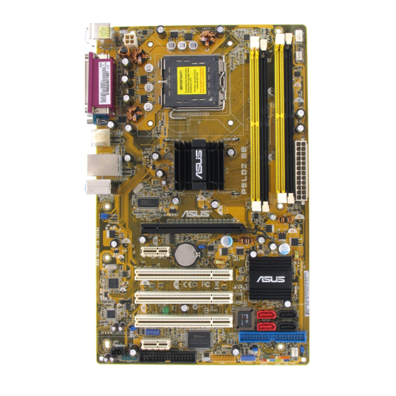
- Page 1 P5LD2 SE...
- Page 2 T2377 © 2005...
- Page 7 • • • • • • • • • • • •...
- Page 8 • • • • •...
- Page 9 Jumper Free Jumper Mode (Default) P5LD2 SE-TAYZ 10839 11036 11XXX11XXX11...
- Page 10 ® ® ® ® ®...
- Page 16 ® ® ® ® ® ®...
- Page 24 Top:Line In Center:Line Out Below:Mic In...
- Page 25 19.0cm(7.5in) PS/2KBMS T:Mouse B:Keyboard ATX12V SPDIF_O LGA775 COM1 USB12 LAN_USB34 Intel 945P Top:Line In Top:Line In Center:Line Out Center:Line Out Below:Mic In Below:Mic In USBPW34 USBPW12 PCIEX16 CLRTC PCIEX1_2 CR2032 3V Lithium Cell CMOS Power PCI1 Intel ICH7 RLT8111B PCI2 SPDIF_OUT SATA4 SATA1...
- Page 26 19.0cm(7.5in) PS/2KBMS T:Mouse B:Keyboard ATX12V SPDIF_O LGA775 COM1 USB12 LAN_USB34 Intel 945P Top:Line In Top:Line In Center:Line Out Center:Line Out Below:Mic In Below:Mic In USBPW34 USBPW12 PCIEX16 CLRTC PCIEX1_2 CR2032 3V Lithium Cell CMOS Power PCI1 Intel ICH7 RLT8111B PCI2 SPDIF_OUT SATA4 SATA1...
- Page 29 ® ® • • • Top:Line In Center:Line Out Below:Mic In P5LD2 SE CPU Socket 775...
- Page 32 ® ® ® ® • ® ® ® • • • • 2-10...
- Page 33 CPU_FAN CPU FAN PWR CPU FAN IN CPU FAN PWM Top:Line In Center:Line Out Below:Mic In P5LD2 SE CPU Fan Connectors 2-11...
- Page 34 2-12...
- Page 35 2-13...
- Page 36 Top:Line In Center:Line Out Below:Mic In P5LD2 SE 240-pin DDR2 DIMM Sockets • • • • 2-14...
- Page 37 256MB SAMSUNG M378T3253FG0-CD5 SAMSUNG K4T560838QF-GCD5 • • 512MB SAMSUNG M378T6553BG0-CD5 SAMSUNG K4T51083QB-GCD5 • • • 512MB Infineon HYS64T64000GU-3.7-A N/A Infineon • • • HYB18T512800AC37SSS11511 512MB Infineon HYS64T64000HU-3.7-A N/A Infineon • • • HYB18T512800AF37SS29334 512MB CORSAIR VS512MB533D2 CORSAIR MIII0052532M8CEC • • • 512MB MICRON MT 16HTF6464AG-53EB2 N/A MICRON...
- Page 38 512MB SAMSUNG KR M378T6553FC0-CE6 N/A SAMSUNG SS K4T51083QC • • • 512MB SAMSUNG KR M378T6453FZ0-CE6 N/A SAMSUNG DS K4T56083QF-ZCE6 • • • 1024MB SAMSUNG KR M378T2953CZ0-CE6 N/A SAMSUNG SS K4T51083QC-ZCE6 • • • 512MB Hynix HYMP564U64AP8-Y4 AA N/A Hynix HY5PS12821AFP-Y4 •...
- Page 39 • • 2-17...
- Page 40 2-18...
- Page 41 2-19...
- Page 42 2-20...
- Page 43 Top:Line In Center:Line Out Below:Mic In Clear CMOS CLRTC Normal (Default) P5LD2 SE Clear RTC RAM 2-21...
- Page 44 USBPW34 +5VSB USBPW12 (Default) Top:Line In Center:Line Out Below:Mic In +5VSB USBPW78 (Default) USBPW56 +5VSB P5LD2 SE USB Device Wake Up (Default) 2-22...
- Page 45 2-23...
- Page 46 ™ ™ ™ 2-24...
- Page 47 FLOPPY Top:Line In Center:Line Out Below:Mic In PIN 1 P5LD2 SE Floppy Disk Drive Connector • • Top:Line In Center:Line Out Below:Mic In PIN 1 PRI_IDE P5LD2 SE IDE Connector 2-25...
- Page 48 SATA1 SATA4 Top:Line In Center:Line Out Below:Mic In SATA2 SATA3 P5LD2 SE SATA Connectors • 2-26...
- Page 49 Top:Line In Center:Line Out Below:Mic In CD(Black) P5LD2 SE Internal Audio Connector AAFP Top:Line In Center:Line Out Below:Mic In P5LD2 SE Analog Front Panel Connector • • 2-27...
- Page 50 Top:Line In Center:Line Out Below:Mic In USB56 USB78 P5LD2 SE USB 2.0 Connectors Top:Line In Center:Line Out Below:Mic In GAME P5LD2 SE Game Connector 2-28...
- Page 51 CPU_FAN CPU FAN PWR CPU FAN IN CPU FAN PWM Top:Line In Center:Line Out Below:Mic In P5LD2 SE CPU Fan Connectors CHASSIS Top:Line In Center:Line Out Below:Mic In Chassis Signal +5VSB_MB (Default) P5LD2 SE Chassis Intrusion Connector 2-29...
- Page 52 Top:Line In Center:Line Out +12V DC +12V DC Below:Mic In Power OK -5 Volts Ground Ground +5 Volts Ground Ground Ground +5 Volts PSON# Ground Ground +3 Volts -12 Volts P5LD2 SE ATX Power Connectors +3 Volts +3 Volts 2-30...
- Page 53 PLED SPEAKER PANEL Top:Line In Center:Line Out Below:Mic In RESET IDE_LED PWRSW Requires an ATX power supply. P5LD2 SE System Panel Connector • • • • • 2-31...
- Page 54 2-32...
- Page 58 ® ® ® ®...
- Page 62 • • A:\>afudos /oOLDBIOS1.rom A:\>afudos /oOLDBIOS1.rom AMI Firmware Update Utility - Version 1.19 (ASUS V2.07(03.11.24BB)) Copyright (C) 2002 American Megatrends, Inc. All rights reserved. Reading flash ..done Write to file ..ok A:\>...
- Page 63 A:\>afudos /iP5LD2-SE.rom A:\>afudos /iP5LD2-SE.ROM AMI Firmware Update Utility - Version 1.19 (ASUS V2.07(03.11.24BB)) Copyright (C) 2003 American Megatrends, Inc. All rights reserved. WARNING!! Do not turn off power during flash BIOS Reading file ..done Erasing flash ..done Search Bootblock version:...
- Page 64 A:\>afudos /iP5LD2-SE.ROM AMI Firmware Update Utility - Version 1.19 (ASUS V2.07(03.11.24BB)) Copyright (C) 2003 American Megatrends, Inc. All rights reserved. WARNING!! Do not turn off power during flash BIOS Reading file ..done Erasing flash ..done Search Bootblock version: 100% Advance Check ..
- Page 65 Bad BIOS checksum. Starting BIOS recovery... Checking for floppy... Bad BIOS checksum. Starting BIOS recovery... Checking for floppy... Floppy found! Reading file “P5LD2-SE.ROM”. Completed. Start flashing...
- Page 66 Bad BIOS checksum. Starting BIOS recovery... Checking for floppy... Bad BIOS checksum. Starting BIOS recovery... Checking for floppy... Floppy not found! Checking for CD-ROM... CD-ROM found. Reading file “P5LD2-SE.ROM”. Completed. Start flashing...
- Page 67 EZFlash starting BIOS update Checking for floppy... EZFlash starting BIOS update Checking for floppy... Floppy found! Reading file “P5LD2-SE.ROM”. Completed. Start erasing..| Start Programming...| Flashed successfully. Rebooting. • •...
- Page 70 4-10...
- Page 71 4-11...
- Page 72 Legacy Diskette A [1.44M, 3.5 in] Use [+] or [-] to Primary IDE Master [ST320413A] configure system time. Primary IDE Slave [ASUS CD-S520/A] Third IDE Master [Not Detected] Third IDE Slave [Not Detected] Fourth IDE Master [Not Detected] Fourth IDE Slave...
- Page 73 Language [English] Use [+] or [-] to Primary IDE Master :[ST320413A] configure system time. Primary IDE Slave :[ASUS CD-S340] Secondary IDE Master :[Not Detected] Secondary IDE Slave :[Not Detected] Third IDE Master :[Not Detected] Fourth IDE Master...
- Page 74 Legacy Diskette A [1.44M, 3.5 in] Primary IDE Master [ST320413A] Use [+] or [-] to configure system time. Primary IDE Slave [ASUS CD-S520/A] Third IDE Master [Not Detected] Third IDE Slave [Not Detected] Fourth IDE Master [Not Detected] Fourth IDE Slave...
- Page 75 Primary IDE Master Select the type Device : Hard Disk of device connected Vendor : ST320413A to the system. Size : 20.0GB LBA Mode : Supported Block Mode : 16 Sectors PIO Mode Async DMA : MultiWord DMA-2 Ultra DMA : Ultra DMA-5 SMART Monitoring: Supported Type...
- Page 76 IDE Configuration When in AHCI/RAID mode SATA Configure SATA As [Standard IDE] controller is Onboard IDE Operate Mode [Enhanced Mode] forced to Native Enhanced Mode Support On [S-ATA] mode. IDE Detect Time Out (Sec) [35] 4-16...
- Page 77 4-17...
- Page 78 AMIBIOS Version : 0106 Build Date : 10/27/05 Processor Type : Genuine Intel(R) CPU 3.20GHz Speed : 3200 MHz Count System Memory Total : 1024MB Appropriated : 0MB Select Screen Available : 1024MB Select Item Change Option General Help Save and Exit Exit 4-18...
- Page 79 JumperFree Configuration Adjust system USB Configuration frequency/voltage. CPU Configuration Chipset Onboard Devices Configuration PCIPnP Configure System Frequency/Voltage Select the targe CPU frequency, and the AI Overclocking [Auto] relevant parameters will be auto-adjusted. Frequencies higher than CPU manufacturer recommends are not guaranteed to be stable.
- Page 80 FSB 1066 266 MHz FSB 800 200 MHz FSB 533 133 MHz Auto DDR2- DDR2- DDR2- DDR2- DDR2- DDR2- DDR2- 600* 800* 899* • • • • • • FSB 1066 • • • • • • FSB 800 • •...
- Page 81 4-21...
- Page 82 USB Configuration Enables USB host controllers. Module Version - 2.24.0-F.4 USB Devices Enabled: None USB Function [Enabled] Legacy USB Support [Auto] USB 2.0 Controller [Enabled] USB 2.0 Controller Mode [HiSpeed] BIOS EHCI Hand-Off [Disabled] 4-22...
- Page 83 Configure Advanced CPU settings Sets the ratio between CPU Core Manufacturer: Intel Clock and the FSB Brand String: Genuine Intel(R) CPU 3.20GHz Frequency. Frequency : 3200 MHz NOTE: If an invalid FSB Speed : 800 MHz ratio is set in CMOS Cache L1 : 16 KB then actual and...
- Page 84 4-24...
- Page 85 Advanced Chipset Settings Enable or disable DRAM timing. Configure DRAM Timing by SPD [Enabled] Hyper Path 3 [Auto] DRAM Throttling Threshold [Auto] Booting Graphic Adapter Priori [PCI Express/PCI] PEG Buffer Length [Auto] Link Latency [Auto] PEG Root Control [Auto] PEG Link Mode [Auto] Slot Power [Auto]...
- Page 86 4-26...
- Page 87 Configure Win627EHF Super IO Chipset Enable or disable High Definition Audio HD Audio Controller [Enabled] Controller. Onboard PCIEX GbE LAN [Enabled] LAN Option ROM [Disabled] Serial Port1 Address [3F8/IRQ4] Parallel Port Address [378] Parallel Port Mode [ECP] ECP Mode DMA Channel [DMA3] Parallel Port IRQ [IRQ7]...
- Page 88 Advanced PCI/PnP Settings NO: Lets the BIOS configue all the WARNING: Setting wrong values in below sections devices in the system. may cause system to malfunction. YES: Lets the Plug And Play O/S [No] operating system PCI Latency Timer [64] configure Plug and Allocate IRQ to PCI VGA [Yes]...
- Page 89 4-29...
- Page 90 Suspend Mode [Auto] Select the ACPI state Repost Video on S3 Resume [No] used for System ACPI 2.0 Support [No] Suspend. ACPI APIC Support [Enabled] APM Configuration Hardware Monitor 4-30...
- Page 91 APM Configuration Go into On/Off or Suspend when Power Power Button Mode [On/Off] button is pressed. Restore on AC Power Loss [Power Off] Power On By RTC Alarm [Disabled] Power On By External Modems [Disabled] Power On By PCI Devices [Disabled] Power On By PCIE Devices [Disabled]...
- Page 92 4-32...
- Page 93 Hardware Monitor AI Quiet [Disabled] CPU Temperature [32.5ºC/90.5ºF] MB Temperature [36.0ºC/96.5ºF] CPU Fan Speed (RPM) [3813RPM] CPU Q-Fan Control [Disabled] Chassis Fan1 Speed (RPM) [N/A] Chassis Q-Fan1 Control [Disabled] Power Fan Speed (RPM) [N/A] VCORE Voltage [ 1.320V] 3.3V Voltage [ 3.345V] 5V Voltage [ 5.094V]...
- Page 94 4-34...
- Page 95 Enter Go to Sub-screen General Help Save and Exit Exit Boot Device Priority 1st Boot Device [1st FLOPPY DRIVE] 2nd Boot Device [PM-ST330620A] 3rd Boot Device [PS-ASUS CD-S360] Select Screen Select Item Enter Go to Sub-screen General Help Save and Exit Exit 4-35...
- Page 96 Allows BIOS to skip Boot Settings Configuration certain tests while Quick Boot [Enabled] booting. This will Full Screen Logo [Enabled] decrease the time AddOn ROM Display Mode [Force BIOS] needed to boot the Bootup Num-Lock [On] system. PS/2 Mouse Support [Auto] Wait For ‘F1’...
- Page 97 Security Settings <Enter> to change password. Supervisor Password : Not Installed <Enter> again to User Password : Not Installed disabled password. Change Supervisor Password Select Screen Select Item Change Option General Help Save and Exit Exit 4-37...
- Page 98 Security Settings Supervisor Password : Not Installed User Password : Not Installed Change Supervisor Password User Access Level [Full Access] Change User Password Clear User Password Password Check [Setup] Select Screen Select Item Change Option General Help Save and Exit Exit 4-38...
- Page 99 Exit Options Exit system setup Exit & Save Changes after saving the changes. Exit & Discard Changes Discard Changes F10 key can be used Load Setup Defaults for this operation. Select Screen Select Item Enter Go to Sub-screen General Help Save and Exit Exit 4-39...
- Page 100 4-40...
- Page 112 • • 5-10...
- Page 113 ® 5-11...
- Page 114 5-12...
- Page 116 ® ® ®...
- Page 117 ® ® ® ® ® ® ® ® ®...
- Page 119 ® ® ® ® ® ®...
Need help?
Do you have a question about the P5LD2 SE and is the answer not in the manual?
Questions and answers