Table of Contents
Advertisement
Advertisement
Table of Contents

Related Manuals for Asus P5K Pro


Summary of Contents for Asus P5K Pro
- Page 1 P5K PRO...
- Page 2 Product warranty or service will not be extended if: (1) the product is repaired, modified or altered, unless such repair, modification of alteration is authorized in writing by ASUS; or (2) the serial number of the product is defaced or missing.
-
Page 3: Table Of Contents
Contents Contents ...................... iii Notices ......................vii Safety information ..................viii About this guide ..................ix P5K PRO specifications summary ............xi Chapter 1: Product introduction Welcome! ..................1-1 Package contents ................. 1-1 Special features ................1-2 1.3.1 Product highlights ............1-2 1.3.2... -
Page 4: Contents
BIOS setup Managing and updating your BIOS ..........4-1 4.1.1 ASUS Update utility ............4-1 4.1.2 ASUS EZ Flash 2 utility ........... 4-4 4.1.3 AFUDOS utility ..............4-5 4.1.4 ASUS CrashFree BIOS 3 utility ........4-7 BIOS setup program ..............4-8 4.2.1... - Page 5 4.6.2 Boot Settings Configuration .......... 4-32 4.6.3 Security ................. 4-33 Tools menu ................. 4-35 4.7.1 ASUS EZ Flash 2 ............4-35 4.7.2 ASUS O.C. Profile ............4-36 4.7.3 ASUS Ai Net 2 ............... 4-37 Exit menu ..................4-38 Chapter 5: Software support Installing an operating system ...........
- Page 6 AI NET2 .................5-11 5.3.3 ASUS PC Probe II ............5-12 5.3.4 ASUS AI Suite ............... 5-18 5.3.5 ASUS EPU Utility—AI Gear 3+ ........5-20 5.3.6 ASUS AI Nap ..............5-22 5.3.7 ASUS Q-Fan 2 .............. 5-23 5.3.8 ASUS AI Booster ............5-24 5.3.9...
-
Page 7: Notices
Notices Federal Communications Commission Statement This device complies with Part 15 of the FCC Rules. Operation is subject to the following two conditions: • This device may not cause harmful interference, and • This device must accept any interference received including interference that may cause undesired operation. -
Page 8: Safety Information
Safety information Electrical safety • To prevent electrical shock hazard, disconnect the power cable from the electrical outlet before relocating the system. • When adding or removing devices to or from the system, ensure that the power cables for the devices are unplugged before the signal cables are connected. -
Page 9: About This Guide
Refer to the following sources for additional information and for product and software updates. ASUS websites The ASUS website provides updated information on ASUS hardware and software products. Refer to the ASUS contact information. Optional documentation Your product package may include optional documentation, such as warranty flyers, that may have been added by your dealer. -
Page 10: Conventions Used In This Guide
Conventions used in this guide To make sure that you perform certain tasks properly, take note of the following symbols used throughout this manual. DANGER/WARNING: Information to prevent injury to yourself when trying to complete a task. CAUTION: Information to prevent damage to the components when trying to complete a task. -
Page 11: P5K Pro Specifications Summary
Supports FSB 1333 / 1066 / 800 MHz Compatible with Intel 05B/05A/06 processors ® Intel Hyper-Threading Technology ready ® * Refer to www.asus.com for Intel CPU support list Chipset Intel P35 / ICH9R with Intel Fast Memory Access ® ®... - Page 12 ASUS AI Lifestyle ASUS Quiet Thermal Solution: Unique features - ASUS EPU (Energy Process Unit) - ASUS 3rd Generation 8-phase Power Design - ASUS AI Nap - ASUS Q Fan 2 ASUS Crystal Sound: - ASUS Noise Filter ASUS EZ DIY:...
- Page 13 System Panel (Q-Connector) BIOS Features 8 Mb Flash ROM, AMI BIOS, PnP, DMI 2.0, WfM 2.0, SM BIOS 2.3, ACPI 2.0a, ASUS EZ Flash 2, ASUS CrashFree BIOS 3 Manageability WfM 2.0, DMI 2.0, WOL by PME, WOR by PME, PXE...
-
Page 15: Chapter 1: Product Introduction
This chapter describes the motherboard features and the new technologies it supports. Chapter 1: Product introduction... - Page 16 Chapter summary Welcome! ..................1-1 Package contents ................. 1-1 Special features ................1-2 ASUS P5K PRO...
-
Page 17: Welcome
® The motherboard delivers a host of new features and latest technologies, making it another standout in the long line of ASUS quality motherboards! Before you start installing the motherboard, and hardware devices on it, check the items in your package with the list below. -
Page 18: Special Features
Super Memspeed Technology To attain top performance, ASUS has managed to break through current FSB and DRAM ratio proportions by utilizing Super Memspeed Technology- the latest technology that provides even more precise overclocking options to unleash the true potential of DDR2 memory. -
Page 19: High Definition Audio
Green ASUS This motherboard and its packaging comply with the European Union’s Restriction on the use of Hazardous Substances (RoHS). This is in line with the ASUS vision of creating environment-friendly and recyclable products/packaging to safeguard consumers’ health while minimizing the impact on the environment. -
Page 20: Asus Ai Lifestyle Unique Features
1.3.2 ASUS AI Lifestyle unique features ASUS Quiet Thermal Solution ASUS Quiet Thermal solution makes system more stable and enhances the overclocking capability. ASUS EPU The ASUS EPU utilizes innovative technology to digitally monitor and tune the CPU power supply with improved VR responses in heavy or light loadings. -
Page 21: Asus Crystal Sound
See page 5-30 for details. ASUS EZ DIY ASUS EZ DIY feature collection provides you easy ways to install computer components, update the BIOS or back up your favorite settings. ASUS Q-Shield... -
Page 22: Asus Intelligent Performance And Overclocking Features
ASUS Intelligent Performance and Overclocking features AI Booster The ASUS AI Booster allows you to overclock the CPU speed in Windows environment without the hassle of booting the BIOS. See page 5-24 for details. Precision Tweaker 2 Allows the user to adjust the NB Voltage, FSB termination Voltage, CPU PLL Voltage and the DRAM Voltage in 0.02v steps to finetune voltages to achieve the... -
Page 23: Chapter 2: Hardware Information
This chapter lists the hardware setup procedures that you have to perform when installing system components. It includes description of the jumpers and connectors on the motherboard. Chapter 2: Hardware information... - Page 24 Chapter summary Before you proceed ..............2-1 Motherboard overview ..............2-2 Central Processing Unit (CPU) ........... 2-6 System memory ................. 2-13 Expansion slots ................2-18 Jumper ..................2-22 Connectors ................. 2-23 ASUS P5K PRO...
-
Page 25: Before You Proceed
The illustration below shows the location of the onboard LED. SB_PWR ® Standby Powered P5K PRO Onboard LED Power ASUS P5K PRO... -
Page 26: Motherboard Overview
2.2 Motherboard overview Before you install the motherboard, study the configuration of your chassis to ensure that the motherboard fits into it. Make sure to unplug the power cord before installing or removing the motherboard. Failure to do so can cause you physical injury and damage motherboard components. -
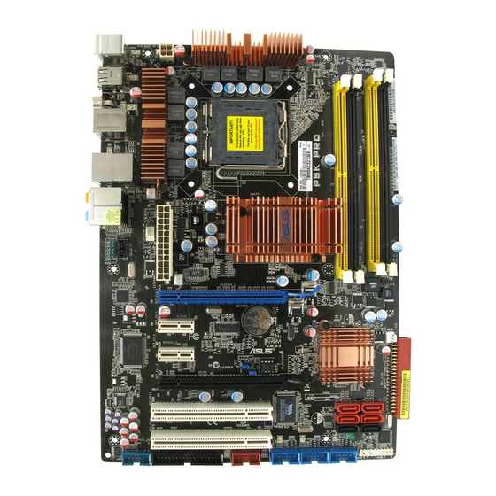
Page 27: Motherboard Layout
CHASSIS DET_X16_2 PCIEX16_2 SATA6 SATA1 SATA5 SATA2 DET_PCI1 SATA4 SATA3 ALC883 PCI1 DET_PCI2 PCI2 SB_PWR SPDIF_OUT FLOPPY IE1394_2 USB1112 USB910 USB78 PANEL COM1 Refer to 2.7 Connectors for more information about rear panel connectors and internal connectors. ASUS P5K PRO... -
Page 28: Layout Contents
2.2.4 Layout contents Slots Page DDR2 DIMM slots 2-13 PCI slots 2-20 PCI Express x 1 slots 2-20 PCI Express x16 slots 2-20 Jumper Page Clear RTC RAM (3-pin CLRTC) 2-22 Rear panel connectors Page PS/2 mouse port (green) 2-23 IEEE 1394a port 2-23 LAN (RJ-45) port... - Page 29 ATX power connectors (24-pin EATXPWR, 4-pin EATX12V) 2-30 Front panel audio connector (10-1 pin AAFP) 2-31 Optical drive audio connector (4-pin CD) 2-32 Digital audio connector (4-1 pin SPDIF_OUT, for ASUS HDMI 2-32 card) System panel connector (20-8 pin PANEL) 2-33 Q-Connector (system panel)
-
Page 30: Central Processing Unit (Cpu)
ASUS will shoulder the cost of repair only if the damage is shipment/transit-related. • Keep the cap after installing the motherboard. ASUS will process Return Merchandise Authorization (RMA) requests only if the motherboard comes with the cap on the LGA775 socket. -
Page 31: Installing The Cpu
To install a CPU: Locate the CPU socket on the motherboard. ® P5K PRO CPU Socket 775 Before installing the CPU, make sure that the cam box is facing towards you and the load lever is on your left. Press the load lever with your thumb (A), then move it to the left (B) until it is released from the retention tab. - Page 32 Lift the load plate with your thumb and forefinger to a 100º angle (A), then push the PnP cap from the load plate window to remove (B). Load plate Alignment key Position the CPU over the socket, making sure that the gold triangle is on the bottom-left corner of the socket then fit the socket...
-
Page 33: Installing The Cpu Heatsink And Fan
CPU fan connector. Motherboard hole Fastener Narrow end of the Make sure to orient each fastener with the narrow end of the groove pointing outward. (The photo shows the groove shaded for emphasis.) ASUS P5K PRO... - Page 34 CPU FAN PWR CPU FAN IN CPU FAN PWM ® P5K PRO CPU fan connector DO NOT forget to connect the CPU fan connector! Hardware monitoring errors can occur if you fail to plug this connector. 2-10 Chapter 2: Hardware information...
-
Page 35: Uninstalling The Cpu Heatsink And Fan
Rotate each fastener counterclockwise. Pull up two fasteners at a time in a diagonal sequence to disengage the heatsink and fan assembly from the motherboard. Carefully remove the heatsink and fan assembly from the motherboard. ASUS P5K PRO 2-11... - Page 36 Rotate each fastener clockwise to ensure correct orientation when reinstalling. Narrow end of the groove The narrow end of the groove should point outward after resetting. (The photo shows the groove shaded for emphasis.) Refer to the documentation in the boxed or stand-alone CPU fan package for detailed information on CPU fan installation.
-
Page 37: System Memory
Channel B DIMM_B1 and DIMM_B2 • This chipset officially supports DDR2-800 MHz. With the ASUS Super Memspeed Technology, this motherboard natively supports up to DDR2-1066 MHz and provides more ratio setting items than the chipset officially supports. See the table below. -
Page 38: Memory Configurations
2.4.2 Memory configurations You may install 512 MB, 1 GB, and 2 GB unbuffered non-ECC DDR2 DIMMs into the DIMM sockets. Sockets Mode DIMM_A1 DIMM_B1 DIMM_A2 DIMM_B2 Populated Single-Channel Populated Dual-channel (1) Populated Populated Dual-channel (2) Populated Populated Populated Populated •... - Page 39 P5K PRO Motherboard Qualified Vendors Lists (QVL) DDR2-1066MHz capability Size Vendor Chip No. Chip Brand SS/ Part No. DIMM support 512MB KINGSTON Heat-Sink Package N/A N/A KHX8500D2/512 • • • 1024MB CORSAIR Heat-Sink Package CM2X1024-8500C5 • • 512MB KINGMAX KKA8FEIBF-HJK- N/A KINGMAX SS KLEC28F-A8KI5-EGAS •...
-
Page 40: Memory Configuration
Dual-channel memory configuration. C*: Supports four modules inserted into both the yellow and black slots • as two pairs of Dual-channel memory configuration. Visit the ASUS website for the latest DDR2-1066/800/667 MHz QVL. 2-16 Chapter 2: Hardware information... -
Page 41: Installing A Dimm
DIMM. Support the DIMM lightly with your fingers when pressing the retaining clips. The DIMM might get damaged when it flips out with DDR2 DIMM notch extra force. Remove the DIMM from the socket. ASUS P5K PRO 2-17... -
Page 42: Expansion Slots
2.5 Expansion slots In the future, you may need to install expansion cards. The following sub-sections describe the slots and the expansion cards that they support. Make sure to unplug the power cord before adding or removing expansion cards. Failure to do so may cause you physical injury and damage motherboard components. -
Page 43: Interrupt Assignments
— — USB 2.0 controller 2 — — shared — — — — — SATA controller 1 — — shared — — — — — SATA controller 2 — shared — — — — used — ASUS P5K PRO 2-19... -
Page 44: Pci Slots
2.5.4 PCI slots The PCI slots support cards such as a LAN card, SCSI card, USB card, and other cards that comply with PCI specifications. The figure shows a LAN card installed on a PCI slot. 2.5.5 PCI Express x1 slots This motherboard supports PCI Express x1 network cards, SCSI cards and other cards that comply with the PCI Express... - Page 45 Some PCI Express graphics cards cannot operate on x4/x1 mode. We suggest that you install these cards on the primary PCI Express slot (blue) to increase system stability. • Some PCI Express devices cannot operate on x4/x1 mode. ASUS P5K PRO 2-21...
-
Page 46: Jumper
® Normal Clear RTC (Default) P5K PRO Clear RTC RAM • You do not need to clear the RTC when the system hangs due to overclocking. For system failure due to overclocking, use the C.P.R. (CPU Parameter Recall) feature. Shut down and reboot the system so the BIOS can automatically reset parameter settings to default values. -
Page 47: Connectors
Line In port (light blue). This port connects the tape, CD, CD player, or other audio sources. Line Out port (lime). This port connects a headphone or a speaker. In 4-channel, 6-channel, and 8-channel configuration, the function of this port becomes Front Speaker Out. 2-23 ASUS P5K PRO... - Page 48 Microphone port (pink). This port connects a microphone. Side Speaker Out port (gray). This port connects the side speakers in an 8-channel audio configuration. Refer to the audio configuration table below for the function of the audio ports in 2, 4, 6, or 8-channel configuration. Audio 2, 4, 6, or 8-channel configuration Port Headset...
-
Page 49: Internal Connectors
PIN 1 NOTE: Orient the red markings on the floppy ribbon cable to PIN 1. P5K PRO Floppy disk drive connector IDE connector (40-1 pin PRI_E IDE) The onboard IDE connector is for the Ultra DMA 133/100/66 signal cable. There are three connectors on each Ultra DMA 133/100/66 signal cable: blue, black, and gray. - Page 50 4.3.6 SATA Configuration for details. Before creating a RAID set, refer to 5.4.3 Intel RAID Configuration or the • manual bundled in the motherboard support DVD. SATA6 SATA1 SATA5 SATA2 ® P5K PRO SATA connectors SATA4 SATA3 2-26 Chapter 2: Hardware information...
-
Page 51: Serial Ata Hard Disk Drive Connection
SATA cable to the onboard SATA port to avoid mechanical conflict with huge graphics cards. When using hot-plug and NCQ, set the Configure SATA as in the BIOS to [AHCI]. See section 4.3.6 SATA Configuration for details. 2-27 ASUS P5K PRO... - Page 52 If your chassis suppots front panel USB ports, you can attach a front panel USB cable to these connectors. Connect the USB cable to ASUS Q-Connector (USB, blue) first, and then install the Q-Connector (USB) to the USB connector onboard.
- Page 53 You can attach a FireWire/1394 cable to this connector if your chassis suppots the front panel IEEE1394 port. Connect the 1394 cable to ASUS Q-Connector (1394, red) first, and then install the Q-Connector (1394) to the 1394 connector onboard.
-
Page 54: Atx Power Connectors
CHASSIS ® (Default) P5K PRO Chassis intrusion connector ATX power connectors (24-pin EATXPWR, 4-pin ATX12V) These connectors are for ATX power supply plugs. The power supply plugs are designed to fit these connectors in only one orientation. Find the proper orientation and push down firmly until the connectors completely fit. -
Page 55: Front Panel Audio Connector
PRESENCE# PORT1 R MICPWR PORT1 L AGND MIC2 P5K PRO Analog front panel connector • We recommend that you connect a high-definition front panel audio module to this connector to avail of the motherboard’s high-definition audio capability. • If you want to connect a high-definition front panel audio module to this connector, make sure that the Front Panel Type item in the BIOS is set to [HD Audio]. - Page 56 Left Audio Channel ® P5K PRO Internal audio connector 11. Digital audio connector (4-1 pin SPDIF_OUT, for ASUS HDMI VGA card) This connector is for an additional Sony/Philips Digital Interface (S/PDIF) port(s). If you are using ASUS HDMI-equipped graphics card, connect the HDMI card to this connector with a S/PDIF out cable.
-
Page 57: System Panel Connector 20-8 Pin Panel
IDE_LED ® PWRSW Requires an ATX power supply. P5K PRO System panel connector • System power LED (2-pin PLED) This 2-pin connector is for the system power LED. Connect the chassis power LED cable to this connector. The system power LED lights up when you turn on the system power, and blinks when the system is in sleep mode. -
Page 58: Asus Q-Connector
ASUS Q-Connector (system panel) You can use the ASUS Q-Connector to connect/disconnect chassis front panel cables in a few steps. Refer to the instructions below to install the ASUS Q- Connector. Connect the front panel cables to the ASUS Q-Connector. - Page 59 This chapter describes the power up sequence, the vocal POST messages, and ways of shutting down the system. Powering up...
- Page 60 Chapter summary Starting up for the first time ............3-1 Turning off the computer ............. 3-2 ASUS P5K PRO...
-
Page 61: Starting Up For The First Time
One continuous beep followed by three No VGA detected short beeps One continuous beep followed by four Hardware component failure short beeps At power on,ㄞ hold down the <Delete> key to enter the BIOS Setup. Follow the instructions in Chapter 4. ASUS P5K PRO... -
Page 62: Turning Off The Computer
3.2 Turning off the computer 3.2.1 Using the OS shut down function If you are using Windows ® Click the Start button then select Turn Off Computer. Click the Turn Off button to shut down the computer. The power supply should turn off after Windows ®... -
Page 63: Chapter 4: Bios Setup
This chapter tells how to change the system settings through the BIOS Setup menus. Detailed descriptions of the BIOS parameters are also provided. BIOS setup... - Page 64 Chapter summary Managing and updating your BIOS ..........4-1 BIOS setup program ..............4-8 Main menu .................. 4-11 Advanced menu ................. 4-16 Power menu ................4-26 Boot menu .................. 4-30 Tools menu ................. 4-34 Exit menu ..................4-37 ASUS P5K PRO...
-
Page 65: Managing And Updating Your Bios
® ASUS EZ Flash 2 (Updates the BIOS using a floppy disk or USB flash disk.) ASUS AFUDOS (Updates the BIOS using a bootable floppy disk) ASUS CrashFree BIOS 3 (Updates the BIOS using a USB flash disk or the motherboard support DVD when the BIOS file fails or gets corrupted.) - Page 66 To update the BIOS through the Internet: desktop by clicking Start Launch the ASUS Update utility from the Windows ® > Programs > ASUS > ASUSUpdate > ASUSUpdate. The ASUS Update main window appears. Select Update BIOS from the Select the ASUS FTP site nearest...
- Page 67 To update the BIOS through a BIOS file: desktop by clicking Start Launch the ASUS Update utility from the Windows ® > Programs > ASUS > ASUSUpdate > ASUSUpdate. The ASUS Update main window appears. Select Update BIOS from a file option from the drop-down menu, then click Next.
-
Page 68: Asus Ez Flash 2 Utility
4.1.2 ASUS EZ Flash 2 utility The ASUS EZ Flash 2 feature allows you to update the BIOS without having to go through the long process of booting from a floppy disk and using a DOS-based utility. The EZ Flash 2 utility is built-in the BIOS chip so it is accessible by pressing <Alt>... -
Page 69: Afudos Utility
The utility returns to the DOS prompt after copying the current BIOS file. Updating the BIOS file To update the BIOS file using the AFUDOS utility: Visit the ASUS website (www.asus.com) and download the latest BIOS file for the motherboard. Save the BIOS file to a bootable floppy disk. ASUS P5K PRO... - Page 70 A:\>afudos /iP5KPRO.ROM The utility verifies the file and starts updating the BIOS. A:\>afudos /iP5KPRO.ROM AMI Firmware Update Utility - Version 1.19(ASUS V2.07(03.11.24BB)) Copyright (C) 2002 American Megatrends, Inc. All rights reserved. WARNING!! Do not turn off power during flash BIOS Reading file ..done Reading flash ..
-
Page 71: Asus Crashfree Bios 3 Utility
4.1.4 ASUS CrashFree BIOS 3 utility The ASUS CrashFree BIOS 3 is an auto recovery tool that allows you to restore the BIOS file when it fails or gets corrupted during the updating process. You can update a corrupted BIOS file using the motherboard support DVD or the USB flash disk that contains the updated BIOS file. -
Page 72: Bios Setup Program
The BIOS setup screens shown in this section are for reference purposes only, and may not exactly match what you see on your screen. • Visit the ASUS website (www.asus.com) to download the latest BIOS file for this motherboard. Chapter 4: BIOS setup... -
Page 73: Bios Menu Screen
At the bottom right corner of a menu screen are the navigation keys for that particular menu. Use the navigation keys to select items in the menu and change the settings. The navigation keys may differ from one screen to another. ASUS P5K PRO... -
Page 74: Menu Items
4.2.4 Menu items The highlighted item on the menu bar Use [ENTER], [TAB], System Time [06:22:54] or [SHIFT-TAB] to System Date [Thu 04/14/2007] displays the specific items for that select a field. Floppy Diskette A [1.44M, 3.5 in.] Language [English] Use [+] or [-] to menu. -
Page 75: Main Menu
Sets the type of floppy drive installed. Configuration options: [Disabled] [720K , 3.5 in.] [1.44M, 3.5 in.] 4.3.4 Language [English] Allows you to select the display language for the BIOS setup screen. Configuration options: [Chinese(BIG5)] [Chinese(GB)] [Japanese] [Français] [German] [English] ASUS P5K PRO 4-11... -
Page 76: Sata 1-6
4.3.5 SATA 1-6 While entering Setup, the BIOS automatically detects the presence of Serial ATA devices. There is a separate sub-menu for each SATA device. Select a device item then press <Enter> to display the SATA device information. BIOS SETUP UTILITY Main SATA 1 Select the type of... -
Page 77: Sata Configuration
If you want to use the Serial ATA hard disk drives as Parallel ATA physical storage devices, keep the default setting [IDE]. If you want the Serial ATA hard disk drives to use the Advanced Host Controller Interface (AHCI), set this item to [AHCI]. ASUS P5K PRO 4-13... -
Page 78: Ahci Configuration
Hard Disk Write Protect [Disabled] Disables or enables device write protection. This will be effective only if the device is accessed through BIOS. Configuration option: [Disabled] [Enabled] SATA Detect Time Out (Sec) [35] Selects the time out value for detecting ATA/ATAPI devices. Configuration options: [0] [5] [10] [15] [20] [25] [30] [35] 4.3.7 AHCI Configuration... -
Page 79: System Information
: 512 MB Select Screen Select Item General Help Save and Exit Exit v02.61 (C)Copyright 1985-2007, American Megatrends, Inc. AMIBIOS Displays the auto-detected BIOS information. Processor Displays the auto-detected CPU specification. System Memory Displays the auto-detected system memory. ASUS P5K PRO 4-15... -
Page 80: Advanced Menu
4.4 Advanced menu The Advanced menu items allow you to change the settings for the CPU and other system devices. Take caution when changing the settings of the Advanced menu items. Incorrect field values can cause the system to malfunction. BIOS SETUP UTILITY Main Advanced Power Boot... - Page 81 Selecting a very high DRAM frequency may cause the system to become unstable! If this happens, revert to the default setting. • The configuration options of the DRAM Frequency item may differ according to the CPU and the DIMM(s) you install. ASUS P5K PRO 4-17...
- Page 82 DRAM Command Rate [Auto] Configuration options: [Auto] [1T] [2T] DRAM Timing Control [Auto] Configuration options: [Auto] [Manual] The following items appear when you set the DRAM Timing Control item to [Manual]. CAS# Latency [5 DRAM Clocks] Configuration options: [3 DRAM Clocks] [4 DRAM Clocks] [5 DRAM Clocks] [6 DRAM Clocks] RAS# to CAS# Delay [5 DRAM Clocks] Configuration options: [3 DRAM Clocks] [4 DRAM Clocks] [5 DRAM Clocks]...
- Page 83 Refer to the DDR2 documentation before adjusting the memory voltage. Setting a very high memory voltage may damage the memory module(s)! North Bridge Voltage [Auto] Allows you to select the north bridge voltage. The values range from 1.25V to 1.91V with a 0.02V interval. ASUS P5K PRO 4-19...
- Page 84 • Setting the CPU PLL Voltage, FSB Termination Voltage, DRAM Voltage and North Bridge Voltage to a high level may damage the chipset, memory module, and CPU permanently. Proceed with caution. • Some values of the CPU PLL Voltage, FSB Termination Voltage, DRAM Voltage and North Bridge Voltage items are labeled in different color, indicating the risk levels of high voltage settings.
-
Page 85: Usb Configuration
Port 64/60 Emulation [Disabled] Allows you to enable or disable the I/O port 60h/64h emulation support. This item should be enabled for the complete USB keyboard legacy support for non-USB aware OSes. Configuration options: [Disabled] [Enabled] ASUS P5K PRO 4-21... - Page 86 Legacy USB Support [Auto] Allows you to enable or disable the support for legacy USB devices. Setting to [Auto] allows the system to detect the presence of USB devices at startup. If detected, the USB controller legacy mode is enabled. If no USB device is detected, the legacy USB support is disabled.
-
Page 87: Cpu Configuration
Configuration options: [Disabled] [Enabled] Execute Disable Bit [Enabled] Allows you to enable or disable the No-Execution Page Protection Technology. Setting this item to [Disabled] forces the XD feature flag to always return to zero (0). Configuration options: [Disabled] [Enabled] ASUS P5K PRO 4-23... -
Page 88: Chipset
PEG Port Control [Auto] PEG Port Force x1 [Disabled] ASUS C.G.I. Function [Auto] Memory Remap Feature [Enabled] Allows you to enable or disable the remapping of the overlapped PCI memory above the total physical memory. Enable this option only when you install 64- bit operating system. -
Page 89: Onboard Devices Configuration
PEG Port Force x1 [Disabled] Configuration options: [Enabled] [Disabled] ASUS C.G.I. Function [Auto] Allows you to configure ASUS Cross Graphics Impeller. Configuration options: [Auto] [Enabled] [Disabled] 4.4.5 OnBoard Devices Configuration BIOS SETUP UTILITY Advanced Onboard Device Configuration Enable or Disable... -
Page 90: Pcipnp
Serial Port1 Address [3F8/IRQ4] Allows you to select the Serial Port1 base address. Configuration options: [Disabled] [3F8/IRQ4] [2F8/IRQ3] [3E8/IRQ4] [2E8/IRQ3] 4.4.6 PCIPnP The PCIPnP menu items allow you to change the advanced settings for PCI/PnP devices. Take caution when changing the settings of the PCIPnP menu items. Incorrect field values can cause the system to malfunction. -
Page 91: Power Menu
Allows you to enable or disable the Advanced Configuration and Power Interface (ACPI) support in the Advanced Programmable Interrupt Controller (APIC). When set to [Enabled], the ACPI APIC table pointer is included in the RSDT pointer list. Configuration options: [Disabled] [Enabled] ASUS P5K PRO 4-27... -
Page 92: Apm Configuration
4.5.5 APM Configuration BIOS SETUP UTILITY Power APM Configuration <Enter> to select whether or not to restart the system Restore on AC Power Loss [Power Off] after AC power loss. Power On By RTC Alarm [Disabled] Power On By External Modems [Disabled] [Disabled] Power On By PCI Devices... -
Page 93: Hardware Monitor
Power fan speed in rotations per minute (RPM). If the fan is not connected to the motherboard, the field shows [N/A]. CPU Q-Fan Control [Disabled] Allows you to enable or disable the CPU Q-fan. Configuration options: [Disabled] [Enabled] The following item appears only when you enable CPU Q-Fan Control. ASUS P5K PRO 4-29... - Page 94 CPU Fan Profile [Optimal] Allows you to set the appropriate performance level of the ASUS Q-Fan. When set to [Optimal], the CPU fan automatically adjusts depending on the CPU temperature. Set this item to [Silent Mode] to minimize fan speed for quiet CPU fan operation, or [Performance Mode] to achieve maximum CPU fan speed.
-
Page 95: Boot Menu
These items specify the boot device priority sequence from the available devices. The number of device items that appears on the screen depends on the number of devices installed in the system. Configuration options: [1st FLOPPY DRIVE] [Hard Drive] [ATAPI CD-ROM] [Disabled] ASUS P5K PRO 4-31... -
Page 96: Boot Settings Configuration
This allows you to enable or disable the full screen logo display feature. Configuration options: [Disabled] [Enabled] Set this item to [Enabled] to use the ASUS MyLogo3™ feature. AddOn ROM Display Mode [Force BIOS] Sets the display mode for option ROM. -
Page 97: Security
Time Clock (RTC) RAM. See section 2.6 Jumper for information on how to erase the RTC RAM. After you have set a supervisor password, the other items appear to allow you to change other security settings. ASUS P5K PRO 4-33... -
Page 98: Change User Password
BIOS SETUP UTILITY Boot Security Settings <Enter> to change password. Supervisor Password : Installed <Enter> again to User Password : Installed disabled password. Change Supervisor Password User Access Level [Full Access] Change User Password Clear User Password Password Check [Setup] Select Screen Select Item Enter Change... -
Page 99: Tools Menu
4.7.1 ASUS EZ Flash 2 Allows you to run ASUS EZ Flash 2. When you press <Enter>, a confirmation message appears. Use the left/right arrow key to select between [Yes] or [No], then press <Enter> to confirm your choice. Refer to section 4.1.2 for details. -
Page 100: Asus O.c. Profile
4.7.2 ASUS O.C. Profile This item allows you to store or load multiple BIOS settings. BIOS SETUP UTILITY Tools O.C. PROFILE Configuration Save to Profile 1 O.C. Profile 1 Status : Not Installed O.C. Profile 2 Status : Not Installed... -
Page 101: Asus Ai Net 2
4.7.3 ASUS Ai Net 2 BIOS SETUP UTILITY Tools Check LAN cable during Pair Status Length POST. N/A N/A N/A Marvell POST Check LAN cable [Disabled] v02.61 (C)Copyright 1985-2007, American Megatrends, Inc. Marvell POST Check LAN Cable [Disabled] Enables or disables checking of the Marvell LAN cable during the Power-On Self-Test (POST). -
Page 102: Exit Menu
4.8 Exit menu The Exit menu items allow you to load the optimal or failsafe default values for the BIOS items, and save or discard your changes to the BIOS items. BIOS SETUP UTILITY Main Advanced Power Boot Tools Exit Exit system setup after saving the changes. -
Page 103: Chapter 5: Software Support
This chapter describes the contents of the support DVD that comes with the motherboard package and the softwares. Software support... - Page 104 Chapter summary Installing an operating system ........... 5-1 Support DVD information ............5-1 Software information ..............5-9 RAID configurations ..............5-30 Creating a RAID driver disk ............5-41 ASUS P5K PRO...
-
Page 105: Installing An Operating System
The contents of the support DVD are subject to change at any time without notice. Visit the ASUS website (www.asus.com) for updates. 5.2.1 Running the support DVD Place the support DVD to the optical drive. -
Page 106: Drivers Menu
Installs the Marvell Yukon Gigabit Ethernet driver. ASUS EPU + AI Gear 3 Driver Installs the EPU + AI Gear 3 driver. Install this driver before the ASUS AI Suite utility. USB 2.0 Driver Installs the USB 2.0 driver. Chapter 5: Software support... -
Page 107: Utilities Menu
Click to display the next page Click to return to the previous page ASUS InstAll-Installation Wizard for Utilities Installs all of the utilities through the Installation Wizard. Marvell Yukon VCT Application Installs the Marvell Yukon Virtual Cable Tester™ (VCT) application that diagnoses ®... - Page 108 ASUS Update The ASUS Update utility allows you to update the motherboard BIOS in Windows ® environment. This utility requires an Internet connection either through a network or an Internet Service Provider (ISP). ASUS PC Probe II This smart utility monitors the fan speed, CPU temperature, and system voltages, and alerts you of any detected problems.
-
Page 109: Make Disk Menu
5.2.4 Make disk menu The Make disk menu contains items to create the Intel ICH9 RAID/AHCI driver disk. Make Intel ICH9 32/64bit RAID/AHCI Driver Disk Allows you to create an ICH9 32/64bit RAID/AHCI driver disk. ASUS P5K PRO... -
Page 110: Manual Menu
Reader from the Utilities menu before opening a user manual file. ® 5.2.6 ASUS Contact information Click the Contact tab to display the ASUS contact information. You can also find this information on the inside front cover of this user guide. Chapter 5: Software support... -
Page 111: Other Information
The icons on the top right corner of the screen give additional information on the motherboard and the contents of the support DVD. Click an icon to display the specified information. Motherboard Info Displays the general specifications of the motherboard. Browse this DVD Displays the support DVD contents in graphical format. ASUS P5K PRO... -
Page 112: Technical Support Form
Technical support Form Displays the ASUS Technical Support Request Form that you have to fill out when requesting technical support. Filelist Displays the contents of the support DVD in text format. P5K PRO Chapter 5: Software support... -
Page 113: Software Information
5.3.1 ASUS MyLogo 3™ The ASUS MyLogo 3™ utility lets you customize the boot logo. The boot logo is the image that appears on screen during the Power-On-Self-Tests (POST). The ASUS MyLogo 3 is automatically installed when you install the ASUS Update utility from the support DVD. - Page 114 Ratio box. When the screen returns to the ASUS Update utility, flash the original BIOS to load the new boot logo. 10. After flashing the BIOS, restart the computer to display the new boot logo during POST.
-
Page 115: Ai Net2
LAN cable(s) connected to the LAN port(s). • If you want the system to check the status of the LAN cable before entering the OS, enable the item Post Check LAN Cable in the BIOS Setup. ASUS P5K PRO 5-11... -
Page 116: Asus Pc Probe Ii
To launch the PC Probe II from the Windows ® > ASUS > PC Probe II > PC Probe II v1.xx.xx. The PC Probe II main window appears. After launching the application, the PC Probe II icon appears in the Windows ®... - Page 117 When displayed, the monitor panel for that sensor also turns red. Refer to the Monitor panels section for details. Preferences You can customize the application using the Preference section in the main window. Click the box before each preference to activate or deactivate. ASUS P5K PRO 5-13...
- Page 118 Hardware monitor panels The hardware monitor panels display the current value of a system sensor such as fan rotation, CPU temperature, and voltages. The hardware monitor panels come in two display modes: hexagonal (large) and rectangular (small). When you check the Enable Monitoring Panel option from the Preference section, the monitor panels appear on your computer’s desktop.
- Page 119 You can enlarge or reduce the browser size by dragging the bottom right corner of the browser. DMI browser Click to display the DMI (Desktop Management Interface) browser. This browser displays various desktop and system information. Click the plus sign (+) before DMI Information to display the available information. ASUS P5K PRO 5-15...
- Page 120 PCI browser Click to display the PCI (Peripheral Component Interconnect) browser. This browser provides information on the PCI devices installed on your system. Click the plus sign (+) before the PCI Information item to display available information. Usage The Usage browser displays real-time information on the CPU, hard disk drive space, and memory usage.
- Page 121 The Preference tab allows you to customize sensor alerts, or change the temperature scale. Loads the default Loads your saved threshold values for Cancels or configuration each sensor ignores your changes Applies your Saves your changes configuration ASUS P5K PRO 5-17...
-
Page 122: Asus Ai Suite
Start > All Programs > To launch AI Suite from the Windows ® ASUS > AI Suite > AI Suite v1.xx.xx. The AI Suite main window appears. After launching the application, the AI Suite icon appears in the Windows taskbar. - Page 123 Displays the CPU/ system temperature, CPU/memory/PCIE voltage, and CPU/ chassis fan speed Displays the FSB/CPU frequency Click on right corner of the expanded window to switch the temperature from degrees Centigrade to degrees Fahrenheit. ASUS P5K PRO 5-19...
-
Page 124: Asus Epu Utility-Ai Gear 3
After installing ASUS AI Suite from the bundled support DVD, you can launch ASUS AI Gear 3 by double-clicking the AI Suite icon on your Windows OS taskbar and then click the AI Gear 3 button on the AI Suite main window. - Page 125 Electricity Savings Calculator window. You may reset the Click time for the calculator to start counting. Click to reset the time the calculator starts Displays the electricity saved since the time was reset ASUS P5K PRO 5-21...
-
Page 126: Asus Ai Nap
5.3.6 ASUS AI Nap This feature allows you to minimize the power consumption of your computer whenever you are away. Enable this feature for minimum power consumption and a more quiet system operation. After installing AI Suite from the bundled support DVD, you can launch the utility by double-clicking the AI Suite icon on the Windows OS taskbar and click the AI Nap button on the AI Suite main window. -
Page 127: Asus Q-Fan 2
5.3.7 ASUS Q-Fan 2 This ASUS Q-Fan 2 Control feature allows you to set the appropriate performance level of the CPU Q-Fan 2 or the Chassis Q-Fan 2 for more efficient system operation. After enabling the Q-Fan 2 function, the fans can be set to automatically adjust depending on the temperature, to decrease fan speed, or to achieve the maximum fan speed. -
Page 128: Asus Ai Booster
5.3.8 ASUS AI Booster The ASUS AI Booster application allows you to overclock the CPU speed in WIndows environment without the hassle of booting the BIOS. ® After installing AI Suite from the bundled support DVD, you can launch the utility... -
Page 129: Asus Ai Direct Link
You must first connect two computers (at least one of them is ASUS product) using a network cable, and then install the utility to both computers to avail the AI Direct Link feature. - Page 130 The authorized user has full access to this folder. The default path of the AIDirectLinkIncoming folder is C:\Program Files\ASUS\AI Direct Link. To change its location, disable the incoming folder first. Then, select disable the incoming folder first. Then, select first.
-
Page 131: Audio Configurations
Audio Manager icon on the taskbar. From the taskbar, double-click on the SoundEffect icon to display the Realtek HD Audio Manager. Realtek HD Audio Manager Realtek HD Audio Manager Exit button Configuration options Minimize button Control settings window Information button ASUS P5K PRO 5-27... -
Page 132: Configuration Options
Information Click the information button ( ) to display information about the audio driver version, DirectX version, audio controller, audio codec, and language setting. Minimize Click the minimize button ( ) to minimize the window. Exit Click the exit button ( ) to exit the Realtek HD Audio Manager. - Page 133 Manager, click the Audio I/O tab. Click the drop-down menu to select the channel configuration. The control settings window displays the status of connected devices. Click for analog and digital options. Click <OK> to effect the Audio I/O settings and exit ASUS P5K PRO 5-29...
- Page 134 Microphone The Microphone option allows you configure your input/output settings and to check if your audio devices are connected properly. To set the Microphone options: From the Realtek HD Audio Manager, click the Microphone tab. Click the Noise Suppression option button to reduce the static background noise when recording. Click the Acoustic Echo Cancellation option button to reduce the echo from the front speakers when recording.
-
Page 135: Raid Configurations
RAID driver from the support DVD to a floppy disk before you install an operating system to the selected hard disk drive. Refer to section “5.5 Creating a RAID driver disk” for details. ASUS P5K PRO 5-31... -
Page 136: Installing Serial Ata Hard Disks
5.4.2 Installing Serial ATA hard disks The motherboard supports Serial ATA hard disk drives. For optimal performance, install identical drives of the same model and capacity when creating a disk array. To install the SATA hard disks for a RAID configuration: Install the SATA hard disks into the drive bays. -
Page 137: Creating A Raid 0 Set (Striped)
Select 2 to 4 disks to use in creating the volume. [↑↓]-Previous/Next [SPACE]-Selects [ENTER]-Selection Complete Use the up/down arrow key to highlight a drive, then press <Space> to select. A small triangle marks the selected drive. Press <Enter> after completing your selection. ASUS P5K PRO 5-33... - Page 138 Use the up/down arrow key to select the stripe size for the RAID 0 array, then press <Enter>. The available stripe size values range from 4 KB to 128 KB. The default stripe size is 128 KB. We recommend a lower stripe size for server systems, and a higher stripe size for multimedia computer systems used mainly for audio and video editing.
-
Page 139: Creating A Raid 1 Set (Mirrored)
WARNING: ALL DATA ON SELECTED DISKS WILL BE LOST. Are you sure you want to create this volume? (Y/N): Press <Y> to create the RAID volume and return to main menu or <N> to go back to Create Volume menu. ASUS P5K PRO 5-35... - Page 140 Creating a RAID 10 set (RAID 0+1) To create a RAID 10 set: From the utility main menu, select 1. Create RAID Volume, then press <Enter>. This screen appears. Intel(R) Matrix Storage Manager Option ROM v5.0.0.1032 ICH9R wRAID5 Copyright(C) 2003-05 Intel Corporation. All Rights Reserved. [ CREATE ARRAY MENU Name: Volume10...
- Page 141 [↑↓]-Change [TAB]-Next [ESC]-Previous Menu [Enter]-Select Enter a name for the RAID 5 set, then press <Enter>. When the RAID Level item is highlighted, press the up/down arrow key to select RAID 5(Parity), then press <Enter>. ASUS P5K PRO 5-37...
- Page 142 The Disks item is highlighted, press <Enter> to select the hard disk drives to configure as RAID. The following pop-up screen appears. [ SELECT DISKS Port Drive Model Serial # Size Status 0 XXXXXXXXXXXX XXXXXXXX XX.XGB Non-RAID Disk 1 XXXXXXXXXXXX XXXXXXXX XX.XGB Non-RAID Disk 2 XXXXXXXXXXXX XXXXXXXX...
-
Page 143: Deleting A Raid Set
ALL DATA IN THE VOLUME WILL BE LOST! Are you sure you want to delete volume “VolumeX”? (Y/N): Press <Y> to delete the RAID set and return to the utility main menu; otherwise, press <N> to return to the Delete Volume menu. ASUS P5K PRO 5-39... -
Page 144: Resetting Disks To Non-Raid
Resetting Disks to Non-RAID Take caution before you reset a RAID volume HDD to non-RAID. Resetting a RAID volume HDD deletes all internal RAID structure on the drive. To reset a RAID set hard disk drive: From the utility main menu, select 3. Reset Disks to Non-RAID, then press <Enter>... -
Page 145: Creating A Raid Driver Disk
Insert a floppy disk into the floppy disk drive or connect a USB flash disk if you are using Windows Vista OS. Follow succeeding screen instructions to complete the process. Write-protect the floppy disk to avoid computer virus infection. ASUS P5K PRO 5-41... - Page 146 To install the RAID driver in Windows XP: During the OS installation, the system prompts you to press the <F6> key to install third-party SCSI or RAID driver. Press <F6> then insert the floppy disk with RAID driver into the floppy disk drive.
-
Page 147: Chapter 6: Ati ® Crossfire™ Technology Support
This chapter tells how to install ATI ® CrossFire™ graphics cards to avail of ATI’s Multi-Video Processing technology. hapter 6: CrossFire™ ® technology support... - Page 148 Chapter summary Overview ..................6-1 Installing CrossFire™ graphics cards ........6-2 Software information ..............6-5 ASUS P5K PRO...
-
Page 149: Overview
Before you begin Uninstall other graphics card drivers in your system To uninstall other graphics card drivers: Close all current applications. Go to Control Panel > Add/Remove Programs. Select your current graphics card driver/s. Select Add/Remove. Restart your system. ASUS P5K PRO... -
Page 150: Installing Crossfire™ Graphics Cards
6.2 Installing CrossFire™ graphics cards Before installing a CrossFire™ system, refer to the user guide that came with the ATI CrossFire™ Edition graphics card. ® To install the graphics cards: Prepare one CrossFire™ Edition (Master) graphics card and one CrossFire™-ready (Slave) graphics card. Slave graphics card Master graphics card Insert the CrossFire™... - Page 151 Insert the CrossFire™-ready (Slave) graphics card into the PCI Express x16 black slot. Make sure that the card is properly seated on the slot. Connect an auxiliary power source from the power supply to the graphics cards. ASUS P5K PRO...
- Page 152 Connect one end of the external cable to the Master graphics card. Connect the other end of the external cable to the Slave graphics card. Connect the loose end to the corresponding port on your monitor. Chapter 6: ATI MVP technology support ®...
-
Page 153: Software Information
Hardware Wizard window. Click Cancel. Place the CrossFire™ installation DVD in your optical drive and install drivers from the opening menu. Click Next to continue from the installation window that appears. Read the License Agreement, then click Yes. ASUS P5K PRO... - Page 154 Select the components that you want to install, then click Next. • Select Express to install the HydraVision™ multi-monitor and desktop management software, as well as the ATI driver. • Select Custom to individually choose desired software components. Setup prepares the installation wizard that will guide you to setup process.
-
Page 155: Using The Catalyst™ Control Center
Start > ATI Catalyst™ Control Center > • On the Windows ® Catalyst™ Control Center • Double-click the Catalyst™ Control Center desktop shortcut. • On the Windows task bar, double- ® click the Catalyst™ Control Center icon. ASUS P5K PRO... -
Page 156: Appendix: Cpu Features
The Catalyst™ Control Center Dialog Box View The Catalyst™ Control Center provides two views: Standard - simple view with wizards for beginners Advance - allows advanced users to access and configure the complete features of the software Set to Advance view to enable the CrossFire™ function. Chapter 6: ATI MVP technology support ®... - Page 157 In the CrossFire™ Settings dialog, tick the box opposite Enable CrossFire™. Click OK to effect the setting. Hotkeys Click the Hotkeys tab on the Catalyst™ Control Center to access the Hotkeys Manager, which allows you to create key combinations as shortcuts for performing certain functions quickly. ASUS P5K PRO...
- Page 158 Profiles Click the Profiles tab on the Catalyst™ Control Center to access the Profiles Manager, which allows you to create customized environments for your desktop, video, and 3D applications. Preferences Click the Preferences tab on the Catalyst™ Control Center to select a language, restore defaults, change skins, or enable/disable the System Tray icon.
- Page 159 Help Click the Help tab on the Catalyst™ Control Center to access the online help system, generate a Problem Report, and get the Catalyst™ Control Center version information. ASUS P5K PRO 6-11...
- Page 160 6-12 Chapter 6: ATI MVP technology support ®...
- Page 161 The Appendix describes the CPU features and technologies that the motherboard supports. CPU features...
-
Page 162: A.1 Intel ® Em64T
Chapter summary Intel ® EM64T ..................A-1 Enhanced Intel SpeedStep Technology (EIST) ......A-1 ® Intel Hyper-Threading Technology ...........A-3 ® ASUS P5K PRO... -
Page 163: Intel ® Em64T
32-bit operating systems. • The motherboard comes with a BIOS file that supports EM64T. You can download the latest BIOS file from the ASUS website (www.asus.com/ support/download/) if you need to update the BIOS file. See Chapter 4 for details. -
Page 164: Using The Eist
A.2.2 Using the EIST To use the EIST feature: Turn on the computer, then enter the BIOS Setup. Go to the Advanced Menu, highlight CPU Configuration, then press <Enter>. Set the Intel(R) SpeedStep Technology item to [Automatic], then press <Enter>. See page 4-22 for details. Press <F10>... -
Page 165: Intel ® Hyper-Threading Technology
Power up the system and enter the BIOS Setup. Under the Advanced Menu, make sure that the item Hyper-Threading Technology is set to [Enabled]. The BIOS item appears only if you installed a CPU that supports Hyper-Threading Technology. Restart the computer. ASUS P5K PRO... - Page 166 Appendix: CPU features...
Need help?
Do you have a question about the P5K Pro and is the answer not in the manual?
Questions and answers