
Related Manuals for Meyer Sound Mina


Summary of Contents for Meyer Sound Mina
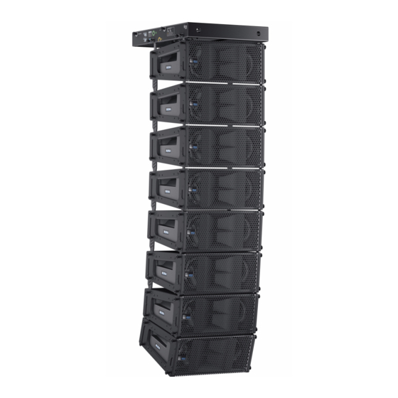
- Page 1 OPERATING INSTRUCTIONS M SERIES MINA Compact Curvilinear Array Loudspeaker Keep these important operating instructions. Check www.meyersound.com for updates.
- Page 2 The contents of this manual are furnished for informational purposes only, are subject to change without notice, and should not be con- strued as a commitment by Meyer Sound Laboratories Inc. Meyer Sound assumes no responsibility or liability for any errors or inaccura- cies that may appear in this manual.
-
Page 3: Important Safety Instructions
2. Keep these instructions. 12. If applicable, use only with the caster rails or rigging 3. Heed all warnings. specified by Meyer Sound, or sold with the loudspeaker. 4. Follow all instructions. Handles are for carrying only. 5. Do not use this loudspeaker near water. -
Page 4: Safety Summary
SAFETY SUMMARY English Ne pas installer l’haut-parleur dans un Um ein Überhitzen dem Lautsprecher endroit où il y a de l’eau ou une humid- zu verhindern, das Gerät vor direkter To reduce the risk of electric shock, dis- ité excessive. Sonneneinstrahlung fernhalten und connect the loudspeaker from the AC nicht in der Nähe von wärmeabstrahl-... -
Page 5: Table Of Contents
CONTENTS Chapter 1: Introduction How to Use This Manual MINA Compact Curvilinear Array Loudspeaker Chapter 2: Power Requirements AC Connectors Wiring for AC Connections AC Power Distribution MINA Voltage Requirements MINA Current Requirements Electrical Safety Issues Chapter 3: Amplification and Audio Audio Connectors Internal connections Cabling... - Page 6 CONTENTS Appendix A: Optional Rain Hood Appendix B: MINA Specifications...
-
Page 7: Chapter 1: Introduction
MINA MINA™ is a compact member of the industry-leading MILO ® family of loudspeakers from Meyer Sound. Measuring just subwoofers. In particular, pay close attention to material over a foot and a half wide (half a meter) and weighing only related to safety issues. - Page 8 500 Hz. The acousti- With its low distortion, flat frequency and phase responses, cal manifold, based on Meyer Sound’s patented REM™ rib- uniform horizontal coverage, and tight vertical coverage, bon emulation technology, radiates driver output with very...
- Page 9 MINA OPERATING INSTRUCTIONS When used in large arrays, typically as a main loudspeaker The MG-MINA grid flies up to 12 MINA cabinets with a 7:1 system, MINA can be flown with the optional MG-MINA grid. safety ratio, or up to 16 MINA cabinets with a 5:1 safety MINA’s end plates include captive GuideALinks™...
- Page 10 CHAPTER 1: INTRODUCTION The MYA-MINA mounting yoke suspends arrays of up to The MUB-MINA U-bracket mounts up to three cabinets for three MINA cabinets from a single point, or pole-mounts up frontfill or under-balcony coverage with up to 20 degrees of to two cabinets (pole-mount adapter not included).
- Page 11 MINA OPERATING INSTRUCTIONS For most applications, Meyer Sound’s 500-HP subwoofer is the logical choice for enhancing low frequencies in MINA loudspeaker systems. The 500-HP can be flown or ground- stacked with MINA arrays using the optional MTF-M’elodie/ MINA transition frame. For applications requiring more low- frequency headroom, Meyer Sound’s 600-HP and 700-HP...
- Page 12 CHAPTER 1: INTRODUCTION...
-
Page 13: Chapter 2: Power Requirements
Each MINA ships with one AC looping connector for making which you will operate the unit. AC looping cables. Assembled AC looping cables are avail- able from Meyer Sound. The AC Input connector also supplies power to any addi- tional loudspeakers connected to the MINA’s gray Loop... -
Page 14: Wiring For Ac Connections
(chassis CAUTION: Before applying AC power to any Meyer Sound self-powered loudspeaker, make AC Cable Wiring Scheme sure that the voltage potential difference between the neutral and earth-ground lines is less than 5 V AC. When wiring international or special-purpose power connec-... -
Page 15: Mina Voltage Requirements
Contact Meyer Sound Technical Support. NOTE: When voltage fluctuates within MINA’s... -
Page 16: Electrical Safety Issues
CHAPTER 2: POWER REQUIREMENTS V pk (drop) = I pk x R (cable total) ELECTRICAL SAFETY ISSUES Pay close attention to these important electrical and safety The Burst Current can also be used to calculate the AC issues. looping capability of MINA. ■... -
Page 17: Chapter 3: Amplification And Audio
100 ohms or less. This same rule applies when looping Pins 2 and 3 carry the input as a differential signal. Pin 1 is MINA loudspeakers with other self-powered Meyer Sound connected to earth through a 1 kOhm, 1000 pF, 15 V loudspeakers and subwoofers. -
Page 18: Internal Connections
INTERNAL CONNECTIONS ■ Increases to the input level have no effect. Meyer Sound loudspeakers are tested and shipped from the ■ Distortion increases due to clipping and nonlinear driver factory with their drivers in correct alignment. If a driver operation. - Page 19 MINA OPERATING INSTRUCTIONS Amplifier Cooling System MINA’s amplifier relies solely on natural convection for cool- ing from air flowing over its heat sink. The efficient design of the amplifier and heat sink profile keeps temperatures low, even when the unit is used at high ambient temperatures in tightly packed conditions, and when driven continuously at high output levels.
- Page 20 CHAPTER 3: AMPLIFICATION AND AUDIO...
-
Page 21: Chapter 4: Line Arrays And System Integration
For high frequencies, MINA uses a very precise Constant Q narrow for most applications, which is why practical system horn, developed using Meyer Sound’s anechoic chamber, designs employ crossovers and multiple elements to which provides a consistent beamwidth of coverage in the achieve controlled directivity across the audio band. -
Page 22: System Design Principles
CHAPTER 4: LINE ARRAYS AND SYSTEM INTEGRATION SYSTEM DESIGN PRINCIPLES High-Frequency Design Strategies Line array designs seek to achieve the following: For far-field coverage, smaller splay angles between cabi- nets achieves superior throw through better coupling. ■ Uniform vertical coverage Longer throws require more elements with smaller splay ■... - Page 23 MINA OPERATING INSTRUCTIONS High-Frequency Equalization Strategies For far-field coverage, air absorption plays a critical role. The longer the distance, the greater the attenuation that occurs for high frequencies. In this zone, high frequencies generally require correction to compensate for energy lost over dis- tance;...
-
Page 24: Compensating For Latency When Integrating Mina Loudspeakers
MINA loudspeakers, this has no effect on system perfor- (M’elodies) and downfill elements (MINAs) must be care- mance. fully considered in order to achieve smooth transitions. However, when integrating MINAs with other Meyer Sound Horizontal Coverage: Horizontal coverage for M’elodie ■ loudspeakers (M’elodies, MICAs, 500-HPs, 600-HPs, and... - Page 25 MINA OPERATING INSTRUCTIONS All system parameters for the Galileo 616 and Galileo 408 ■ Compensate for air absorption at high frequencies with can be configured from the extensive Compass™ software each section having unique correction settings appropri- ate for the distance of the intended coverage.
-
Page 26: Using Digital Signal Processors
Galileo loudspeaker manage- height of the array (number of cabinets) determines the total ment system to drive Meyer Sound loudspeakers, the SPL and low frequency energy (proportional to the upper- loudspeakers can also be driven from third-party dig- frequency spectrum). - Page 27 Sound’s SIM 3 should be used to determine appropriate delay and polarity settings. Integrating 600-HP and 700-HP Subwoofers MINA arrays can be deployed with Meyer Sound’s 600-HP or 700-HP subwoofers in applications where high SPL is necessary, or the program content requires additional low- frequency headroom.
- Page 28 CHAPTER 4: LINE ARRAYS AND SYSTEM INTEGRATION...
-
Page 29: Chapter 5: Quickfly Rigging
When installing Meyer Sound loudspeakers and subwoof- ers, the following precautions should always be observed: ■ All Meyer Sound products must be used in accordance with local, state, federal, and industry regulations. It is the owner’s and user’s responsibility to evaluate the reli- ability of any rigging method for their application. - Page 30 CHAPTER 5: QUICKFLY RIGGING Front GuideAlinks The label in the lower left corner of the end frame shows the splay angle for the GuideALink position. With the knob at the The front GuideALinks act as a pivot point between linked bottom, the splay angle is 0 degrees.
-
Page 31: Mg-Mina Grid
MINA OPERATING INSTRUCTIONS above them, whether they are flown or ground- CAUTION: Always use the quick-release pins stacked, and other factors. MAPP Online Pro is rec- included with the MG-MINA grid to secure its ommended for determining the optimum splay angles links, as well as to secure groundstacked MINAs to for loudspeakers and coverage pattern of the array. - Page 32 CHAPTER 5: QUICKFLY RIGGING TIP: The tilt for the MG-MINA and the array Groundstacking MINAs with the MG-MINA hung below it can be further tilted by using The MG-MINA grid can also be used for groundstacking up chain motors, or differing lengths of steel or to six MINAs.
-
Page 33: Mtf-M'elodie/Mina Transition Frame
MINA OPERATING INSTRUCTIONS MTF-M’ELODIE/MINA TRANSITION FRAME When using MINA for downfill in M’elodie arrays, the MTF-M’elodie/MINA transition frame links the bottom M’elodie to the top MINA. The transition frame can also transition from 500-HP subwoofers (fitted with rigging frames) to MINA in flown and groundstacked arrays. -
Page 34: Mya-Mina Mounting Yoke
CHAPTER 5: QUICKFLY RIGGING MYA-MINA MOUNTING YOKE The MYA-MINA mounting yoke flies up to three MINA loud- speakers from a single hanging point using a C-clamp or equivalent. The yoke includes two bracketing options: the MPA-2 for attaching to two cabinets, and the MPA-3 for attaching to one or three cabinets. -
Page 35: Mub-Mina U-Bracket
MINA OPERATING INSTRUCTIONS Pole-Mounting MINAs with the MYA-MINA also be flown from trusses using C-clamps or equivalent. For flying and groundstacking larger arrays, the MG-MINA Up to two MINA loudspeakers can be pole-mounted with grid is recommended; for applications requiring continuous the MYA-MINA mounting yoke. -
Page 36: Floor- And Pole-Mounting Minas With The Mya-Mina
CHAPTER 5: QUICKFLY RIGGING FLOOR- AND POLE-MOUNTING MINAS WITH MCF-MINA CASTER FRAME THE MYA-MINA The MCF-MINA caster frame safely supports up to five Up to two MINA loudspeakers can be floor- or pole- MINAs for transport and groundstacking, making it easy to mounted with the MUB-MINA mounting yoke. - Page 37 MINA OPERATING INSTRUCTIONS Safety Guidelines for the MCF-MINA Caster Frame ■ Do not stack more than five MINAs. ■ Avoid moving stacks in the front-to-back direction of the MINAs (the long side); always move stacks sideways to avoid tipping. MCF-MINA Caster Frame with MINA Stack...
- Page 38 CHAPTER 5: QUICKFLY RIGGING...
-
Page 39: Chapter 6: Rms Remote Monitoring System
RMS network. RMS software provides extensive system status and perfor- RMS provides real-time monitoring of multiple Meyer Sound mance data for each loudspeaker, including amplifier volt- self-powered loudspeakers from a Windows-based com- age, limiting activity, power output, driver status, as well as puter. -
Page 40: Rms Module
CHAPTER 6: RMS REMOTE MONITORING SYSTEM The RMS software displays all loudspeakers on the network Identify Button in a panel with icons, Meter views, and Text views that can The Identify button serves the following functions: be customized to suit your needs. Loudspeaker data is ■... - Page 41 MINA OPERATING INSTRUCTIONS Remote Mute Switch The recessed Remote Mute switch on MINA’s RMS user panel determines whether the RMS software can control muting and soloing of the loudspeaker. MINA ships from the factory with the switch enabled. RMS Module ■...
- Page 42 CHAPTER 6: RMS REMOTE MONITORING SYSTEM...
-
Page 43: Chapter 7: System Design And Integration Tools
Online Pro, Meyer Sound’s patented online acoustical pre- are based on 360 1/48th-octave-band measurements taken diction tool, and SIM 3, a comprehensive system for mea- with a SIM audio analyzer in the Meyer Sound anechoic surement and analysis. chamber. The extraordinary consistency between Meyer... -
Page 44: Sim 3 Measurement System
The MAPP Online Pro client software is regularly upgraded ■ Measuring propagation delays between subsystems to to add support for the latest Meyer Sound loudspeakers, as determine appropriate polarities and delay times well as to add feature enhancements. Most upgrades are Measuring variations in frequency response caused by ■... - Page 45 APPENDIX A: OPTIONAL RAIN HOOD A weather-protected version of MINA is available with a rain INSTALLING THE MINA RAIN HOOD hood that safeguards the loudspeaker’s electronics from the To install the MINA rain hood: elements when used outdoors. The rain hood — which 1.
- Page 46 APPENDIX A: OPTIONAL RAIN HOOD...
- Page 47 APPENDIX B: MINA SPECIFICATIONS ACOUSTICAL Operating Frequency 66 Hz – 18 kHz Range Note: Recommended maximum operating frequency range. Response depends on load- ing conditions and room acoustics. Frequency Response 70 Hz – 17.5 kHz ±4 dB Note: Measured free field with 1/3 octave frequency resolution at 4 meters. Phase Response 1 kHz to 18 kHz ±30°...
- Page 48 APPENDIX B: MINA SPECIFICATIONS AMPLIFIER Type Three-channel, Class-D Output Power 975 W total (three channels; 2 x 375 W, 1 x 225 W) Note: Wattage rating based on the maximum unclipped burst sine-wave rms voltage the amplifier will produce into the nominal load impedance: 39 V rms low channels, 43 V rms high channel.
- Page 49 MINA OPERATING INSTRUCTIONS Humidity To 95% at 35° C Operating Altitude To 4600 m (15,000 ft) Non operating Altitude To 95% at 35° C Shock 30 g 11 msec half-sine on each of 6 sides Vibration 10 Hz – 55 Hz (0.010 m peak-to-peak excursion)
- Page 50 APPENDIX B: MINA SPECIFICATIONS MINA Dimensions with Rain Hood 20.27 [515 mm] 7.60 [193 mm] 3.75 18.53 [95 mm] [471 mm] 8.38 10° [213 mm] 5.85 3.56 4.19 [149 mm] [90 mm] [106 mm] 18.95 [481 mm] 15.32 [389 mm] MINA Dimensions with Rain Hood...
- Page 52 Meyer Sound Laboratories Inc. 2832 San Pablo Avenue Berkeley, CA 94702 www.meyersound.com © 2010 Meyer Sound. All rights reserved. T: +1 510 486.1166 MINA — 05.207.005.01 A F: +1 510 486.835...
Need help?
Do you have a question about the Mina and is the answer not in the manual?
Questions and answers