Table of Contents
Advertisement
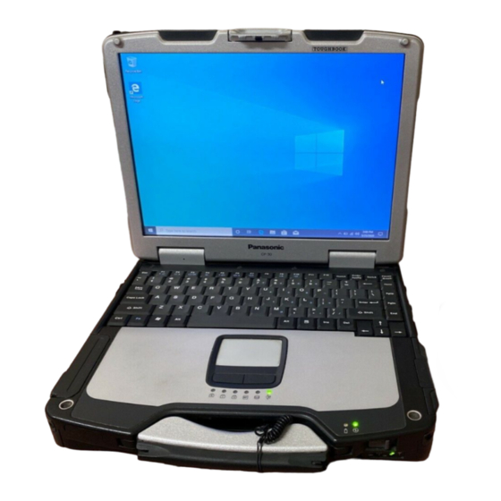
Model No. CF-30CTQAZ 1 2
1: Operation System
B: Microsoft® Windows® XP Professional
L: Microsoft® Windows® XP Professional MUI
2: Area
E /G /F /T /P /S /L /2: Refer to above area table
CF-30 SERIES
Model No.
© 2006 Matsushita Electric Industrial Co., Ltd. All rights reserved.
Unauthorized copying and distribution is a violation of law.
ORDER NO.
Notebook Computer
This is the Service Manual for
the following areas.
E ...for U.K.
G ...for Germany
F ...for France
T ... for Italy
P ... for Spain
S ... for Sweden
L ... for Belgium
2 ... for UK
CPD0611207C2
Advertisement
Table of Contents

Related Manuals for Panasonic CF-30CTQAZ1 TOUGHBOOK


Summary of Contents for Panasonic CF-30CTQAZ1 TOUGHBOOK
-
Page 1: Notebook Computer
L: Microsoft® Windows® XP Professional MUI 2: Area E /G /F /T /P /S /L /2: Refer to above area table © 2006 Matsushita Electric Industrial Co., Ltd. All rights reserved. Unauthorized copying and distribution is a violation of law. -
Page 2: How To Replace The Fuse
WARNING For U.K. This apparatus must be earthed for your safety. To ensure safe operation the three-pin plug must be inserted only into a standard three-pin power point which is effectively earthed through the normal household wiring. Extension cords used with the equipment must be three-core and be correctly wired to provide connec- tion to earth. -
Page 3: Laser Safety Information
LASER SAFETY INFORMATION For U.S.A. Class 1 LASER-Product This product is certified to comply with DHHS Rules 21 CFR Subchapter J. This product complies with European Standard EN60825 (or IEC Publication 825) For all areas This equipment is classified as a class 1 level LASER product and there is no hazardous LASER radiation. Caution: (1) Use of controls or adjustments or performance of procedures other than those specified herein may result in hazardous radiation exposure. -
Page 6: Table Of Contents
CONTENTS 1. Specifications ··················································································································1-1 2. Names and Functions of Parts ······················································································2-1 3. Block Diagram ···············································································································3-1 4. Diagnosis Procedure ·····································································································4-1 5. Power-On Self Test (Boot Check) ·················································································5-1 6. List of Error Codes <Only when the port replicator is connected> ································6-1 7. Self Diagnosis Test ········································································································7-1 8. -
Page 7: Specifications
1 Specifications Main Specifications Model No. CF-30CTQAZBE/CF-30CTQEZL2 ® Intel Core™ Duo Processor L2400 (1.66 GHz, 2 MB L2 cache, 667 MHz FSB) ® Chipset Intel 945GM *1*2 Memory 512 MB (4096 MB Max.) *1*3 Video Memory UMA (128 MB Max.) Hard Disk Drive 80 GB Display Method... - Page 8 ® ® Operating System Microsoft Windows XP Professional Service Pack 2 with Advanced Security Technologies (NTFS File System) ® ® Utility Programs DMI Viewer, Microsoft Windows Media Player 10, Adobe Reader, PC Information Viewer, ® ® SD Utility, Icon Enlarger, Loupe Utility, Intel Matrix Storage Manager, Intel PROSet/Wireless ®...
-
Page 9: Names And Functions Of Parts
2 Names and Functions of Part A: Bluetooth Antenna : Hard disk drive status <Only for model with Bluetooth> : Power status of the multimedia pocket Reference Manual “Bluetooth” : Battery status Reference Manual “Battery Power” B: ExpressCard Slot : Power status Reference Manual “PC Card / ExpressCard”... - Page 10 Right side 1394 Rear side Bottom A: Hard Disk Drive M: External Display Port Reference Manual “External Display” Reference Manual “Hard Disk Drive” B: SD Memory Card Slot N: Headphone Jack You can connect headphones or ampliÞ ed speakers. Reference Manual “SD Memory Card” When they are connected, audio from the internal C: SD Memory Card Indicator speakers is not heard.
-
Page 11: Block Diagram
3 Block Diagram 1Gbytes/sec... -
Page 12: Diagnosis Procedure
4 Diagnosis Procedure 4.1. Basic Procedures... - Page 13 4.2. Troubleshooting Flow Chart...
-
Page 14: Power-On Self Test (Boot Check)
5 Power-On Self Test (Boot Check) -
Page 15: List Of Error Codes
6 List of Error Codes <Only when the port replicator is connected> nnnn nnnn nnnn nnnn nnnn nnnn... - Page 16 device device device device nnnn nnnn nnnn nnnn...
-
Page 17: Self Diagnosis Test
7 Self Diagnosis Test... - Page 20 7.1. Test Item and Division of trouble...
-
Page 22: Wiring Connection Diagram
8 Wiring Connection Diagram EXTERNAL EXPANSION DISPLAY HEAD MICRO SERIAL PORT PORT PORT PHONE PHONE PORT CN100 CN705 CN703 CN102 CN101 CN702 CN701 CN700 JK701 JK700 I/O PCB USB PCB BACK LIGHT CN103 PORT ANTENNA TOUCH SCREEN INVERTER PCB CN201 TS PCB CN200 EXT ANT. -
Page 23: Disassembly/Reassembly
9 Disassembly/Reassembly Note: Power off the computer. Do not shut down to the Suspend or hibernation mode. Do not add peripherals while the computer is in the Suspend or hibernation mode; abnormal operation may result. 9.1. 9.1.2. Disassembly Instructions Removing the Battery Pack and HDD Pack 9.1.1. -
Page 24: Removing The Hdd
9.1.3. 9.1.4. Removing the HDD Removing the KB Cover, Hinge Cover L, Hinge Cover R and Key- HDD U Case Ass’y board HDD FPC <N5> <N5> <K1-16> Bluetooth PCB <N5> Heater Sheet <N5> <N5> <N2> Hinge Cover L <N5> Sheet Sheet <N5>... - Page 25 9.1.5. 9.1.6. Removing the KB Cable Cover and Removing the GPS PCB and Blue- LCD Cable Cover tooth PCB <N4> <N12> <N4> <N12> <N4> <N4> <N12> GPS BT Angle <N4> <N4> <N12> KB Cable Cover GPS PCB <N4> <N4> Bluetooth Cable Cover <N11>...
- Page 26 9.1.7. 9.1.8. Removing the DIMM Cover and Bot- Removing the USB PCB and Antenna tom Cover Tape <N1> <N1> <N1> <N1> Connector (CN100) DIMM Cover <N5> USB PCB <N1> <N5> <N5> Antenna PCB Antenna Cable Connector Cover DIMM Stopper Base (White) <N3>...
-
Page 27: Removing The Main Pcb
9.1.9. 9.1.10. Removing the PAD PCB Removing the FPC HDD BAT to Connector (CN8) TP PCB Screw Sheet to Connector (CN7) <N16> FPC HDD BAT to Connector (CN9) <N4> Tape <N4> <N4> to Connector (CN800) <N4> <N4> Antenna Cable Sheet <N4>... - Page 28 (CN400,CN401) <N18> 11. Remove the 2 Screws. <N5> <N16> 12. Remove the 2 Screws. <N21> <N16> to Connector(CN700) 13. Remove the MP Guide. <N16> to Connector(CN701) 14. Remove the MP PCB. <N16> <N16> <N16> 15. Remove the Coin Battery Cushion. 16.
- Page 29 9.1.12. Removing the SD PCB, Express Card 9.1.13. Removing the I/O PCB and PCMCIA Card I/O PCB Connector <N22> (CN701) <N22> <N22> Connector <N22> (CN700) <N15> <N22> Lib Cover <N22> <N22> Connector Cover <N14> Express Card <N15> <N22> <N14> <N5> PCMCIA Card SD PCB <N5>...
- Page 30 9.1.14. Removing the Palm Top Cover Sheet, 9.1.15. Removing the Handle and Power SW Palm Top Cover, Touch Pad Adhe- <K2-41> sion Seat, Touch Pad, Touch Pad SW Handle Base L Knob, LED PCB and SW LED PCB Handle Base R <K2-41>...
-
Page 31: Removing The Display Unit
9.1.16. Removing the Display Unit 9.1.17. Removing the LCD Rear Cabinet, Hinge L and R Display Unit <N13> left LCD Cover <N7> Side Cover <N7> <N7> <N9> LCD Rear Cabinet <N7> <N7> <N7> <N9> <N9> <N7> <N13> <N9> <N7> <N7> <N7>... - Page 32 9.1.18. Removing the Inverter PCB, TS PCB 9.1.19. Removing the Antenna PCB L and R and LCD Unit LCD Rear Cabinet Ass’y W-LAN ANT Cover L Antenna PCB L LCD Drop Holder Connector Connector (CN201) (CN200) TS PCB LCD Drop <N2>...
-
Page 33: Reassembly Instructions
9.2. Reassembly Instructions 9.2.1. Attention when CF-30 series is repaired • Please execute writing BIOS ID when you exchange the Main Board. • Parts (Sheet and rubber) etc. related various the Conductive Cloth and Heat Spreader cannot be recycled. Use new parts. 9.2.2. - Page 34 9.2.3. Setting the Inverter PCB, TS PCB and LCD Unit 1. Set the LCD Unit to the LCD Front Cabinet in order. 2. Attach the 2 drop holders. LCD Drop Holder 3. Connect the Cable to the Connector. (CN200,CN201) 4. Connect the 3 Cables to the 3 Connectors. Connector Connector 5.
- Page 35 Assembly of LCD Unit * Notes: 1. Apply the load when attaching the parts. 20N to 30N (2 to 3Kgf)/cm2 Confirm that the LCD LCD Drop Holder Insertion Cushion is not wrapped. Attach the Inverter MIL Shierd LCD Front Ass’y Match to the LCD edge and attach it.
-
Page 36: Setting The Display Unit
9.2.5. Setting the Display Unit 1. Fix the Display Unit using the 4 Screws. <N9> No1 to No4 2. Fix the Display Unit using the 2 Screws. <N10> No1, No2 Display Unit Note: No.1 Tighten the Screws in the numbered order (No1 to No2). <N9>... - Page 37 9.2.7. Setting the Palm Top Cover Sheet, Palm Top Cover, Touch Pad Adhesion Seat, Touch Pad SW Knob, LED PCB And SW LED PCB 1. Set the SW LED PCB. 2. Attach the Power LED Packing Sheet to the LED Spacer Sheet.
- Page 38 Assembly of Power SW Attach the Battery Cushion Connection Direction Bottom Battery Pack Insertion Slot Cable Power * Notes: Connection 1. Apply the load when attaching the parts. 20N to 30N (2 to 3Kgf)/cm2 CAB Wall Connection Direction Tighten of Screw Attach the Battery Slide Sheet (on Battery Cushion) FPC Power SW is set Power SW LED...
- Page 39 9.2.8. 9.2.9. Setting the I/O PCB Setting the SD PCB, Express Card and PCMCIA Card 1. Open the Connector Cover and Lid Cover. 2. Fix the I/O PCB using the 4 Screws. <N15> No1 to No4 1. Fix the PCMCIA Card using the 4 Screws. <N22> 3.
- Page 40 9.2.10. Setting the Main PCB 17. Attach the Tape. 1. Fix the Main PCB using the 7 Screws <N5> and Screw. <N21> Tape <N11> No1 to No8. <N21> Coin Battery 2. Set the Modem Cable. Connector MP Guide Cushion Connector (CN401) 3.
- Page 41 24. Fix the Screw. <N7> 25. Attach the TOP Screws. TOP Screw Sheet <N7> Connector (CN17) Connector (CN27) Note: Tighten the Screws in the numbered order (No1 to No8). Tighten the Screws in the numbered order (No1 to No6). Screws <N5>: DRQT26+D4FKL Screws <N7>: DRSB26+10HKL Screws <N11>: DFHE5025XA Screws <N16>: DRQT26+E5FKL...
- Page 42 Assembly of LAN, Modem and MDC * Notes: 1. Apply the load when attaching the parts. 20N to 30N (2 to 3Kgf)/cm2 Order of fixing Tighten of Screw Screw Screw Modem LAN Case Tighten of is installed. Screw Pass the Cable to the back from the hole of the A side.
- Page 43 9.2.11. Setting the PAD PCB 1. Fix the PAD PCB using the 2 Screws. <N4> 2. Attach the TP PCB Screw Sheet. TP PCB Screw Sheet 3. Connect the Cable to the Connector. (CN802) 4. Connect the Cable to the Connector (CN801) and attach the Tape.
- Page 44 9.2.12. Setting the FPC HDD BAT 1. Fix the FPC HDD BAT using the Screw. <N16> to Connector (CN8) 2. Connect the 2 Cables to the 2 Connectors. (CN7,CN8) to Connector (CN7) 3. Connect the Cable to the Connector. (CN800) <N16>...
- Page 45 1. Set HDD Guide and fix with Screw. Tighten of Screw 2. Fix with Screw. 3. Apply tetra coating to each connector pin. Direction A View FPC HDD Battery is set Do not Fold. Direction B View Battery HDD Connector Angle is set This Connector does not need tetra coating.
- Page 46 Insert the Plug into the Socket The terminal of the antenna Relay Circuit Board Ass’y cable must not come in contact with this terminal. Cable (Put it on the metal fittings side. ) Insert FPC into Relay Circuit Board Ass’ys socket Figure seen from direction of arrow of A Lock after FPC insertion Mountain Fold (Straight Line)
- Page 47 Assembly of USB PCB and Antenna PCB * Notes: Safety Working Safety Working 1. Apply the load when attaching the parts. 20N to 30N (2 to 3Kgf)/cm2 Attach the Antenna Cable Sheet Attach the Tape Fit to the groove. Set on the top. Difference : 1 or less Antenna Cable Order of fixing...
- Page 48 9.2.14. Setting the DIMM Cover and Bottom Cover 1. Set the Bottom Cover. No.5 No.2 No.3 2. Fix the Bottom Cover using the 6 Screws. <N8> No1 to No6 No.4 <N1> <N1> <N1> <N1> 3. Fix the Bottom Cover using the 13 Screws. <N6> No1 to No13 DIMM Cover 4.
- Page 49 Preparation of DIMM Cover * Notes: 1. Apply the load when attaching the parts. 20N to 30N (2 to 3Kgf)/cm2 DIMM Cover is set 0.5mm Attach the DIMM Cover Cushion 0.5mm Attach the DIMM Cover Spacer 0.5mm 0.5mm Safety Working * Notes: Attach the CD Edge Sheet Keyboard Cable Cover is installed...
- Page 50 9.2.15. Setting the GPS PCB and Bluetooth PCB 1. Fix the GPS BT Angle and GPS PCB using the 2 Screws. <N12> <N11> 2. Connect the Cable to the Connector on GPS PCB. <N12> <N12> GPS BT Angle 3. Fix the GPS Ass’y using the 4 Screws. <N12> <N12>...
- Page 51 9.2.16. Setting the KB Cable Cover, Keyboard and LCD Cable Cover 1. Set the Keyboard onto the Computer. No.5 No.3 2. Connect the 2 Cables to the 2 Cables. (CN13,CN14) <N4> <N4> 3. Fix the KB Cable Cover using the 7 Screws. <N4> No1 to No.1 No.7 No.4...
- Page 52 7.2.17. Setting the KB Cover, Hinge Cover L, Hinge Cover R and Keyboard 1. Insert the front hooks of the Keyboard to the Top Cabinet in No.3 <N5> order, and set the Keyboard. <N5> 2. Fix the Hinge Cover L and R using the 4 Screws <N5> No1 Bluetooth PCB No.1 to No3...
- Page 53 Preparation oh HDD ASSY * Notes: 1. Apply the load when attaching the parts. 20N to 30N (2 to 3Kgf)/cm2 Fit to the corner. Attach the HDD Tape L HDD is set Attach the HDD Tape S Turn it to the board side (back side). 1.
- Page 54 * Notes: HDD Damper Ass’y 1. Apply the load when attaching the parts. 20N to 30N (2 to 3Kgf)/cm2 Push and bend Make sure the product with black sheet on the yellow sponge. Fold the FPC from the board edge. HDD Ass’y HDD Set Insert after removing the Release Paper of the two-sided tape.
- Page 55 When attaching HDD Cushion Plate and HDD Cushion (Black), * Notes: set the bending part of the metal plate up. 1. Apply the load when attaching the parts. 20N to 30N (2 to 3Kgf)/cm2 HDD Thermal Plate Do not bend it at a sharp angle to put natural R.
- Page 56 * Notes: 1. Apply the load when attaching the parts. 20N to 30N (2 to 3Kgf)/cm2 11 1 Right and left position: Match to the center Top and bottom position: Match the edge of the base material transparent sheet to the bottom side (20) HDD Side Damper is installed HDD Side Damper...
- Page 57 Set the CN side first, and then set the TAB side pushing to the A direction. SATA Guide Set HDD Ass’y insertion SATA Guard is installed Insert to make the Cushion on the HDD inside of the Cushion on the lower case. Avoid getting HDD under the side damper when inserting HDD * Notes:...
- Page 58 9.2.19. Setting the Battery Pack and HDD Pack 1. Set the HDD Pack. 2. Set the Battery Pack. Battery Cover HDD Cover Battery Pack HDD Pack 9-36...
- Page 59 10 E xploded V iew E1001 N4 N4 N4 K116 K115 K162 K109 K1-17 K1-17 K1-3 K1-1 K1-7 K129 K1-16 K1-9 K1-12 K1-8 Screw tightening torque 0.19 _ 0.02 N.m K1-4 K1-11 (2.0 _ 0.2 kgf.cm) K1-18 K1-10 K1-5 0.45 _ 0.05 N.m K1-14 (4.5 _ 0.5 kgf.cm) K1-4...
- Page 60 K2-16 K2-16 K2-3 K2-6 K2-5 K2-5-3 K2-10 K2-6-2 K2-5-1 K2-6-5 K2-6-1 K2-3-4 K2-3-1 K2-10-8 K2-5-2 K2-3-3 K2-10-1 K2-6-4 K2-10-3 K2-3-2 K2-5-4 K2-6-1 K2-39 K2-10-8 K2-6-3 K2-10-5 K2-10-2 K2-39 K2-6-3 K2-10-1 K112 K104 K101 K2-10-4 K100 K2-8 K2-39 K2-8-10 K2-10-6 K2-8-2 K2-4 K2-10-7 K2-8-1...
- Page 61 K159 K156 K157 K158 K120 K2-11 K2-29 K117 K2-12 K2-19 K130 K2-28 K2-40 K135 K149 K123 K118 K144 K153 N22 N22 Screw tightening torque K137 0.19 _ 0.02 N.m (2.0 _ 0.2 kgf.cm) 0.216 _ 0.0196 N.m (2.2 _ 0.2 kgf.cm) K152 K145 K143 0.314 _ 0.0196 N.m K133 (3.2 _ 0.2 kgf.cm) K134 K139 K136 K141 0.49 _ 0.05 N.m (5.0 _ 0.5 kgf.cm) K146 K155 K150 K145...
- Page 62 K2-33 K2-32 K2-39 K2-39 K2-34 K3-8 K3-8 K3-2 K3-8 K3-5 K3-3 K3-4 K3-6 K3-1 Screw tightening torque 0.45 _ 0.05 N.m (4.5 _ 0.5 kgf.cm) 0.8 _ 0.1N.m (8.0 _ 1.0 kgf.cm) 0.3 _ 0.05 N.m (3.0 _ 0.5 kgf.cm) 0.19 _ 0.05 N.m (2.0 _ 0.5 kgf.cm) CF-30CTQAZxx 10-4...
- Page 63 K9-2-1 K9-2-1-1 K9-2 K9-2-2 K9-2-3 K9-1-3 K10-1 K10-2 K9-1-2 K9-1-4 K9-4 K9-3 K9-1-3 Screw tightening torque 0.19 _ 0.02 N.m (2.0 _ 0.2 kgf.cm) K9-1 0.45 _ 0.50 N.m K9-1-1 (4.5 _ 0.5 kgf.cm) 0.441 _ 0.049 N.m K9-1-3 (4.5 _ 0.5 kgf.cm) K9-1-4 1.47 _ 0.20 N.m (15 _ 2.0 kgf.cm) K9-1-3 1.30 _ 0.17N.m (13.0 _ 2.0 kgf.cm) CF-30CTQAZxx 10-5...
- Page 64 E35-2 E35-5 E35-10 E35-1 E35-3 E35-8 E35-4 E35-6 E35-3 E35-7 E35-4 E35-10 E35-9 Screw tightening torque 0.19 _ 0.02 N.m (2.0 _ 0.2 kgf.cm) 0.45 _ 0.05 N.m (4.5 _ 0.5 kgf.cm) 0.216 _ 0.0196 N.m (2.2 _ 0.2 kgf.cm) 0.314 _ 0.0196 N.m (3.2 _ 0.2 kgf.cm) 0.49 _ 0.05 N.m (5.0 _ 0.5 kgf.cm) CF-30CTQAZxx 10-6...
- Page 65 K13-2 K13-1 Screw tightening torque 0.19 _ 0.02 N.m (2.0 _ 0.2 kgf.cm) 0.45 _ 0.05 N.m (4.5 _ 0.5 kgf.cm) 0.216 _ 0.0196 N.m (2.2 _ 0.2 kgf.cm) 0.314 _ 0.0196 N.m (3.2 _ 0.2 kgf.cm) 1.47 _ 0.20 N.m (15 _ 2.0 kgf.cm) 0.49 _ 0.05 N.m (5.0 _ 0.5 kgf.cm) CF-30CTQAZxx 10-7...
-
Page 66: Replacement Parts List
Replacement Parts List Note : Important Safety Notice Components identified by mark have special characteristics important for safety. When replacing any of these components, use only manufacturer's specified parts. CF-30CTQAZxx REF. NO and AREA PART NO. DESCRIPTION Q'TY Main Block Unit DL3UP1336BAA PCB UNIT FOR EXT ANT DL3UP1354CAA... - Page 67 *OPERATING INSTRUCTION MANUAL DFJS954ZA MODEM CABLE Note: About the parts which written " * " above, please order to Computer Products Europe (CPE) written below. Matsushita Electric (U.K.) Ltd. Computer Products Europe (CPE) TEL: +44-(0)29-20736170 FAX: +44-(0)29-20736250 Packing Material DFPH0064ZA PACKING PAPER...
- Page 68 K2-2-4 DFHR6257ZA WIRELESS SW CASE K2-2-5 DFHR6258ZA-0 WIRELESS SW KNOB K2-2-6 DFMD7B10ZA WM OFF SW PLATE K2-2-7 XTB2+4GFN SCREW K2-3 S DFKE8185ZA-0 MP LATCH ASS'Y K2-3-1 DFUQ0113ZA SD LATCH SPRING K2-3-2 DRHM0110ZAT SCREW K2-3-3 DFBD0190ZA-0 MP LATCH LEVER K2-3-4 S DFKE0861ZA-0 MP LATCH CASE K2-4 S DFKE8186ZA-0...
- Page 69 K2-10-4 DFHR3E58ZA CN PACKIN-SLIDE K2-10-5 S DFKE0868ZA-0 CN COVER K2-10-6 S DFKE0875ZA-0 CN SLIDE COVER K2-10-7 DFMD7B11ZA CN WATER PROOF PLATE K2-10-8 DRQT26+D3KLT SCREW K2-11 DFJS1030ZA SP CABLE K2-12 L0AA04C00012 SPEAKER K2-13 DFGE0111YA-0 TOP LOOK SHEET K2-14 DFGE0145ZA-0 REAR BELT COVER SHEET K2-15 DFGL0153ZA-0 SD LABEL...
- Page 70 K9-2 DFWV84A0277 TOUCH SCREEN PANEL KIT K9-2-1 DL3DV0183AAA TOUCH SCREEN PANEL K9-2-1-1 DFHR9068ZA PROTECTIVE FILM K9-2-2 DFHP7246ZA TS FIXED TAPE K9-2-3 DFHR3695ZA TS FPC SPACER K9-3 DFHE0843ZA LCD MAGNET K9-4 DFHG1929ZA MAGNET CUSHION DFBS8003ZA-0 LCD LATCH ASS'Y K10-1 DFBS0073ZA-0 LCD LATCH K10-2 DFHR6313ZA LCD LATCH SLIDER...
- Page 71 DFMC0863ZA INV SHIELD CASE DFMC0873ZA INV MIL SHIELD DFMC0874YA INV SHEILD TAPE DFMC0876ZA INV SHIELD CASE OUTSIDE DFMX1241ZA INVERTER CASE DFQT9664ZA-1 TOUGH BOOK LABEL(W) DFHP7261YA KB SPACER TAPE DFHR3E65WA KB SPACER SHEET DFHR3G46ZA KB HOOK SPACER LOWER DFHR6260ZA-0 KB COVER DFMD7B05YA-0 KB BACK PLATE DFQT0045ZA...
- Page 72 K122 DFMD4067ZA-0 SERIAL COVER PLATE K123 DFMD4069ZA ICH PLATE K124 DFMD7B00ZA BATT HDD CN ANGLE K126 DFMX0702ZA INSULATION SHEET K129 DFMX1006ZA CABLE SHEET K130 DFMX1256ZA TP INS SHEET K131 DFHG1403YA-0 KB SUPPORT RUBBER K132 DFHG1467ZA LEAD SW CUSHION K133 DFHP7275ZA CN TAPE L K134 DFHP7276ZA...
- Page 73 Replacement Parts List Note: Important Safety Notice Components identified by mark have special characteristics important for safety. When replacing any of these components use only manufacturer's specified parts. CF-30CTQAZxx REF. NO and AREA PART NO. DESCRIPTION Q'TY MAIN PCB C 1, 2, 3, 5, 6, 7, 10, 11, 12, F1J0J106A013 CAPACITOR, 6.3V, 10µF 15, 16, 18, 19, 20, 22, 23,...
- Page 74 C 141, 142, 143, 144, 145, F1G1A104A014 CAPACITOR, 10V, 0.1µF 146, 210, 211, 269, 282, 321, 322, 323, 325, 326, 329, 330, 334, 344, C 192, F1G1H6R0A544 CAPACITOR, 50V, 6.0pF C 194, F1G1H5R00004 CAPACITOR, 50V, 5pF C 208, 513, F1G1C473A004 CAPACITOR, 16V, 0.047µF C 218, 220, F1G1H2R0A543...
- Page 75 CN 19, K1KA02AA0262 CONNECTOR CN 20, K1KA08AA0266 CONNECTOR CN 21, K1MYL0B00003 CONNECTOR CN 22, K1MYL0B00004 CONNECTOR CN 24, K1KY12A00004 CONNECTOR CN 25, K1MN10BA0134 CONNECTOR CN 26, K1KA02BA0014 CONNECTOR CN 28, K1FY104B0009 CONNECTOR CN 31, K1KA12BA0014 CONNECTOR CN 37, K1MY52BA0190 CONNECTOR D 1, 2, 3, 6, 7, 19, MA2J72900L DIODE...
- Page 76 IC 52, C0CBCBC00137 IC, REGULATOR IC 54, 63, 64, 66, C0JBAA000345 IC, LOGIC IC 55, 110, C0JBAB000624 IC 56, C0JBAE000321 IC, LOGIC IC 65, 72, 96, 101, 102, 107, C0JBAB000621 IC, LOGIC IC 67, C1CB00002268 IC, SECURITY CHIP IC 70, C0ABBA000093 IC, OP AMP IC 71,...
- Page 77 R 8, 9, 29, 31, 37, ERJ2RKF1000X RESISTOR, 1/16W, 100Ω R 10, 406, 407, 444, ERJ2RKF1001X RESISTOR, 1/16W, 1KΩ R 11, ERJ2RKF2001X RESISTOR, 1/16W, 2KΩ R 13, ERJ2RKF51R0X RESISTOR, 1/16W, 51Ω R 14, 16, ERJ2RKF27R4X RESISTOR, 1/16W, 27.4Ω R 15, 17, 32, 33, ERJ2RKF54R9X RESISTOR, 1/16W, 54.9Ω...
- Page 78 R 170, 210, 485, 486, 487, ERJ2GEJ105X RESISTOR, 1/16W, 1MΩ 488, 489, 582, R 175, 190, 197, 235, 320, ERJ2GEJ474X RESISTOR, 1/16W, 470KΩ 327, 328, 329, 348, 364, 465, 483, 524, 525, 537, R 198, 199, 269, 270, 271, ERJ2RHD103X RESISTOR, 1/16W, 10KΩ...
- Page 79 R 547, ERA3EEB1692V RESISTOR, 1/16W, 16.9KΩ R 549, 550, ERJ2RHD302X RESISTOR, 1/16W, 3KΩ R 551, 552, D1BDR0680001 RESISTOR, 1/8W, 0.068Ω R 586, RL1220SR15F RESISTOR, 1/8W, 0.15Ω R 590, ERJ2RKF1602X RESISTOR, 1/16W, 16KΩ R 598, ERJ2RKF1202X RESISTOR, 1/16W, 12KΩ R 604, 605, ERJ6GEYJ122V RESISTOR, 1/10W, 1.2KΩ...
- Page 80 CN 800, K1MN14BA0059 CONNECTOR CN 801, K1MY04BA0104 CONNECTOR CN 802, K1MN10BA0059 CONNECTOR D 800, DED1SS355T17 DIODE IC 800, C1DB00001417 IC, FLAT PAD CONTROLLER Q 800, 801, B1GKCFJN0004 TRANSISTOR R 805, 806 ERJ2GEJ222X RESISTOR, 1/16W, 2.2KΩ R 800, ERJ2GEJ224X RESISTOR, 1/16W, 220KΩ R 801, 803, ERJ2GEJ822X RESISTOR, 1/16W, 8.2KΩ...
- Page 81 Q 203, UNR9213J0L TRANSISTOR R 200, 206, ERJ2GEJ473X RESISTOR, 1/16W, 47KΩ R 203, 205, 207, 209, 210, ERJ2GEJ102X RESISTOR, 1/16W, 1KΩ 211 212 217 220 221 R 208, ERJ2GEJ273X RESISTOR, 1/16W, 27KΩ R 213, 214, 215, 216, ERJ2GEJ822X RESISTOR, 1/16W, 8.2KΩ R 218, ERJ2GEJ512X RESISTOR, 1/16W, 5.1KΩ...