
Related Manuals for Hanna Instruments PCA 310


Summary of Contents for Hanna Instruments PCA 310
- Page 1 Instruction Manual PCA 310, PCA 320, PCA 330 Chlorine, pH, Temperature, ORP Analyzers w w w. h a n n a i n s t . c o m...
- Page 2 Please read this instruction manual carefully before using the instrument. It will provide you the necessary information for the correct use of the instrument, as well as a more precise idea of its versatility. Hanna Instruments reserves the right to modify the design, construction and appearance of its products without advance notice.
-
Page 3: Table Of Contents
TABLE OF CONTENTS PRELIMINARY EXAMINATION........6 GENERAL DESCRIPTION..........7 MECHANICAL DIMENSIONS........9 FUNCTIONAL DESCRIPTION........10 DISPLAY, LEDS AND KEYBOARD........11 SPECIFICATIONS............14 OPERATING DESCRIPTION.........16 Chlorine measurement ........16 Method of analysis ........17 pH and temperature measurement ....17 ORP measurement ........17 INITIAL PREPARATION AND INSTALLATION....18 Installation Personnel........18 Location of the Instrument.......18 Hydraulic Connections........18 Installing the Input Filter........20 Installing the pH and ORP probes .....20... - Page 4 Changing the password ......... 33 Setting the language ........33 Analyzer serial number and software version ..33 Time and date ..........33 WORKING MODE ........... 34 Automatic mode .......... 34 Standby mode ..........34 Manual mode ..........34 Read on demand ........... 35 Direct read ..........
- Page 5 Analog output..........48 Alarms ............49 ORP SETTINGS (PCA 330) ..........50 Measure info ..........50 Analog output ..........50 Alarms ............51 ANALOG OUTPUT ..........52 Select the analog output type ......52 Dosing through 4-20 mA output ...... 52 CALIBRATE THE ANALOG OUTPUT ......53 Output middle range ........54 SYSTEM LOG ............55...
-
Page 6: Preliminary Examination
Note: Because of the inherent dangers in handling chemical samples, standards and reagents, HANNA Instruments strongly rec- ommends the users of this product to review the Material Safety Data Sheets and become familiar with safe handling proce-... -
Page 7: General Description
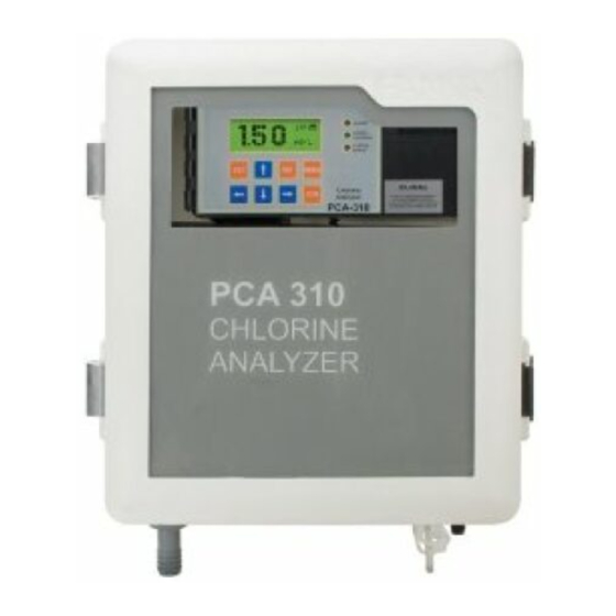
GENERAL DESCRIPTION The Hanna PCA 310, PCA 320 and PCA 330 series of chlo- rine, pH, ORP and temperature analyzers are microprocessor controlled, process analyzers which continuously monitor a sample stream for chlorine content, pH, ORP and temperature values. The PCA 310-330 monitor the free chlorine or total chlorine in the 0 to 5 mg/L range depending on the factory settings and used reagents. - Page 8 13 standards. Molded fiberglass polyester has outstanding chemical and temperature resistance. The case provides wall mounting capability and door gasket assures a watertight and dust-tight seal. The electrical and hydraulic connections are made through the side of the enclosure. The front cover is secured with two lockable latches. Four chlorine level setpoints can be adjusted by the operator: a proportional dosing setpoint, two alarm setpoints and a minimum level for dosing.
-
Page 9: Mechanical Dimensions
The analyzer can store up to 3500 readings (at least 7 days at 3 minutes sampling interval), that are available for consulting or downloading. The PCA 310-330 analyzers can be monitored or controlled through RS485 or GSM network connection. Errors, alarms and warnings are sent through SMS (using GSM module HI 504900). -
Page 10: Functional Description
FUNCTIONAL DESCRIPTION 1. Alarms, dosing, system error LED’s 13. Buffer Bottle 14. Pressure Regulator Output Port 2. Character Display 3. Cable glands 15. Incoming Pressure Regulator 4. Keypad 16. Indicator Bottle 5. Peristaltic Pump 17. Sample Inlet Port 18. pH Electrode (not included) 6. -
Page 11: Display, Leds And Keyboard
DISPLAY, LEDS AND KEYBOARD DISPLAY ALARM DOSING CHLORINE DOSING ACID/ALK. LEDS SYSTEM ERROR MENU KEYPAD Chlorine/pH/ORP Analyzer PCA-330 DISPLAY The display contains 4 lines with 20 characters on one line. The information and error messages are clearly displayed in plain language, without error codes. The display has back light for better visibility. - Page 12 16:35 1.35 mg/L Alarm <Cl Calibration Old> Min:0.00 Max5.00 1 - measured value (chlorine, pH, ORP or temperature) 2 - measurement units (mg/L, pH, mV, °C or °F) 3 - current time in format HH:MM 4 - warnings, alarms and errors, displayed one at a time 5 - secondary information.
- Page 13 LEFT and RIGHT ARROWS • select an error message, • select an item to edit or • select the current digit for editing. MENU MENU enter in menu mode. CFM confirm the selected menu and edited values. SET starts editing the selected item. •...
-
Page 14: Specifications
SPECIFICATIONS t u l ± ± ± t n i i n i n i l t u l ± ± s i s t u l ± ±... - Page 15 C ° ° t u l C ° ± C ° ± C ° l a i n i l s i l a t I a i l , s r i n r l e r l e r t e l º...
-
Page 16: Operating Description
OPERATING DESCRIPTION CHLORINE MEASUREMENT Referring to the drawing on page 10 and the Fluidic Diagram on page 17, the Sample Line is connected to the instrument at the Sample Port (#17); an internal Regulator (#15) reduces the inlet pressure from a maximum of 4 bar (57.2 psi) down to 1 bar (14.3 psi);... -
Page 17: Method Of Analysis
METHOD OF ANALYSIS O DRAIN Free available SAMPLE OUTLET chlorine oxidizes DETECT the DPD indicator reagent at a pH SAMPLE OUTLET between 5.5 and STIR PRESSURE SOLENOID REGULAT SAMPLE 6.0 to form a ma- MAGNET g e n t a - c o l o r e d compound. -
Page 18: Initial Preparation And Installation
Hanna Instruments assumes that persons performing the in- stallation tasks are aware of the appropriate safety procedures. CAUTION:Review the Material Safety Data Sheets (MSDS) before han- dling the supplied chemical reagents. - Page 19 A 1/2 BSP sample input fitting allows direct connection to the optional input filter. Sample line pressure should be between 0.07 and 4 bar (1 and 57.2 psi) with an ideal pressure of 0.7 bar (10 psi). It is recommended to assure that the water inlet come at 1 m above the instrument sample input pitting.
-
Page 20: Installing The Input Filter
Return Line Installation The return hose fitting is a 12 mm (1/2”) hose barb on the bottom of the regulator output port and should always be connected even when pressure is below 1 bar. INSTALLING THE INPUT FILTER In order to ensure maximum accuracy of measurements, it is recommended to have always clear sample, with suspended particles smaller than 0.5 μm. -
Page 21: Installing The Pump Tubes
the protective cap from electrodes and electrodes connectors. HI 1005 HI 1005 Screw the pH probe (HI 1005 HI 1005 HI 1005) in the lower position and the ORP probe HI 2008 HI 2008 (HI 2008 HI 2008 HI 2008) in the higher position and assure that no leakage occurs. Only after the probe is in final position connect the probe to the dedicated connector. -
Page 22: Electrical Connections
them. Place the indicator bottle (HI 70450 for free chlorine and HI 70460 for total chlorine) on the right and the buffer bottle (HI 70451 for free chlorine and HI 70461 for total chlo- rine) on the left. Note: Add the content of 5 HI70452 sachets, DPD Compound, to the Indicator Solution prior to installing it. - Page 23 3) Open front panel. 4) Remove the cover screws (Allen head). 5) Do not remove peristaltic pump or motor. 6) Unplug all alarms and recorder jacks. Feed the power cord through the watertight grommet and tighten the grommet nut. See the picture below for proper wire connections.
- Page 24 Alarm Relay A system alarm feature provides relay activation ALARM to signal that the measuring value exceed the alarm setpoints. The alarm relay is closed (Com- mon connect to Normal Close) if the value is C NO NC lower than alarm low setpoint or higher than alarm high setpoint.
- Page 25 Acid/alkali Dosing Relay Acid/alk dosing relay is activated (Common connected DOSING DOSING to Normal Open) depending on the setpoint and selected delta. If the analyzer is set to dose acid, the relay is active when the pH value is over the setpoint. If alkaline is dosed, the relay is activated when the C NO pH value is under the setpoint.
-
Page 26: Startup
In this phase, the integrity of the stored data is checked and the information regarding the language is loaded. The display will show HANNA INSTRUMENTS, the name of the instrument and the software version. Note: If the instrument is set for free chlorine analysis, the software will report at startup Free Chlorine and if it is set for total chlorine, the software will report at startup Total Chlorine. -
Page 27: User Interface
USER INTERFACE PANELS ORGANIZATION The PCA 310 – 330 analyzers provide a friendly interface that display all important parameters of the analyzer. The appearance of the display could be selected by the user. The panels are organized in circular loops. PCA UP/DOWN 330 has a main loop Main panels... -
Page 28: Measure Panels
One row with messages is also displayed. When the display 08:10 show one of this pan- 6.29 pH Error els, pressing “CFM”, < Low ORP > will enter in the pan- Min:4.18 Max:7.00 els related to the pa- rameter displayed in the left side. -
Page 29: Messages
The display go in large digits panel if no key 16:49 is pressed for about 4 minutes. If key is mg/L pressed, the display returns in the panel where it was before. Pressing “ESC” when in one of those panels will return in main panels mode. -
Page 30: Navigating Through Menu
If correct password is entered and confirmed, the analyzer will go in menu mode. If wrong password is entered, the analyzer displays “Password incorrect. Settings are not allowed!”, and the user could only view the analyzer parameters. NAVIGATING THROUGH MENU The menu is organized as a list of options. - Page 31 For list type parameter In this case the cursor will blink and first letter alternates with a black square. To modify the value press “UP” or “DOWN” arrow key until the correct value appears. Setpoint :2.50 mg/L Delta :0.1 mg/L Low Point:0.02 mg/L Low Point:Inactive Press “CFM”...
-
Page 32: Programming The Analyzer
Pressing “RIGHT” or “LEFT” arrow keys, another parameter can be set. Pressing “ESC” key will return to menu. Note: If the edited value is outside the allowed range, a warning panel appears when “CFM” is pressed. This panel contains the parameter limits. Pressing again “CFM” or “ESC” will return to the edit mode. -
Page 33: General Settings
GENERAL SETTINGS System Log The analyzer settings, Analog Output common for all mea- SMS Settings surements, are grouped Serial & GSM Comm. in “General Menu”. Time and Date System Functions CHANGING THE PASSWORD Language Change The password is a numeric value with 4 digits. To change the password, enter in “General Menu”... -
Page 34: Working Mode
WORKING MODE Three working modes Work Mode:AUTOMATIC could be selected for Read On Demand the analyzer. The selec- Alarm Relay :ON tion is available in Dose Cl Rel :ON “General Menu” - Dose pH Rel :ON “System Functions” - Sys.Err. Rel:OFF “Manual Commands”... -
Page 35: Read On Demand
READ ON DEMAND When this function is selected, (“General Menu” - “System Functions” - “Manual commands” - “Read On Demand”) a new chlorine measuring cycle is immediately started. This command is useful when calibrate or whenever an imme- diate result is needed. Note: The read on demand function is active only when the analyzer is in automatic mode. -
Page 36: Chlorine Settings
CHLORINE SETTINGS The settings related to chlorine measurement are grouped in “Chlo- rine Menu”. The fol- lowing options are available: REAGENT CHANGING One set of reagents is enough for at least 16000 samples. The remaining doses of reagent are displayed on one chlorine mea- suring panel. -
Page 37: Measure Settings
MEASURE SETTINGS Select “Chlorine Menu” - “Measure Settings” and set the “Period” between 3 and 90 minutes. Period (sampling rate) is the elapsed time between two con- secutive chlorine measurements. The sampling rate is also important when the analyzer is used for chlorine dosing. For larger pools, the period must be longer, and for smaller pools, the period must be shorter. -
Page 38: Chlorine Dosing
The output will be proportional with chlorine if the read value is between those limits. Example: if the 0.0 to 20.0 mA recorder output has been selected, the operator can select 0.0 mA to correspond to a concentration of 3.00 mg/L (Min. Rec. setting) and 20.0 mA to correspond to a concentration of 4.50 mg/L (Max. -
Page 39: Alarms
To modify the Delta, edit the “Delta” line. The available values are 0.1, 0.2, 0.3, 0.4, 0.5, 0.6, 0.7, 0.8, 0.9, 1, 1.5, 2, 3, 4, 5. Note: The speed of the analyzer could be modified by changing the sampling rate. A new decision regarding the chlorine regula- tor is taken only after a new measurement. -
Page 40: Calibrate The Measuring Cell
The alarms could be separately activated or inactivated. To modify the alarms status, enter the “Chlorine Menu” - “Alarms Chlorine” menu and edit “Alarm Hi” or “Alarm Lo” status. When the status is set to “Inactive”, the alarm is ignored. Note: The Alarm high must be greater than Alarm low value. -
Page 41: Ph Settings (Pca 320, Pca 330)
• With a calibrated meter take a measure of the sample. This is the calibration value. • Wait for the PCA to display the new reading. • Go in “Chlorine menu” - “Cal. Measuring Cell” and edit “Cal. Value” field. •... -
Page 42: Analog Output
ANALOG OUTPUT The type of analog output could be set as described in “Ana- log output” chapter. The analog output span for pH could be set in “pH Menu” - “Analog Output pH”. “Min. Rec” will set the recorder low limit and “Max. Rec” will set the recorder high limit. - Page 43 The analog output will have the value: analog output [mA] = 4 + 16 * dosing time/Period [mA] Note: If the measured pH is lower (or higher for acid dosing) than setpoint minus (plus) delta, the dosing will be continuous until the pH period elapsed.
-
Page 44: Alarms
To modify this protection, edit “pH Menu” - “Dosing control pH” - “Max. ON” value. The allowed range is between 30 and 720 minutes. ALARMS Two alarm setpoints are available for pH: Alarm high and Alarm low. The ALARM LED and relay are activated when the pH value is higher than Alarm high or lower than Alarm low. -
Page 45: One Point Calibration
For accurate calibration use two different beakers for each buffer solution, the first one for rinsing the probe and the second one for calibration. By doing this, contamination between buffers is minimized. Unscrew the probe from its position. Take care to stop the sample flow before removing the probe. -
Page 46: Two-Points Calibration
• The analyzer prompts for the second buffer selection, and displays the message “Select buffer pH... or press SET for one point cal.”. Pressing “SET” key will end the one point calibration procedure. TWO-POINTS CALIBRATION • To perform a two-points pH calibration follow the steps de- scribed at one-point calibration until the analyzer displays the message: “Select buffer pH... -
Page 47: Set Default Calibration
• Wait for readings to stabilize. • Enter in “pH Menu”- “Cal. pH Probe” - “Process pH Cal.” and enter in the Cal. Value:06.84 pH “Cal. Value” field the reading from the reference pH meter. • Press “CFM” key when the analyzer prompt for “Over- write pH cal. -
Page 48: Temperature Settings (Pca 320, Pca 330)
TEMPERATURE SETTINGS (PCA 320, PCA 330) Settings related to temperature mea- surement are grouped “Temperature Menu”. The following options are available: UNITS The analyzer could display the Temperature using Celsius or Fahrenheit temperature units. To select the temperature units, edit the “Temperature Menu” - “Units”... -
Page 49: Alarms
“Min. Rec” will set the recorder lower limit and “Max. Rec” will set the recorder higher limit. The Max. Rec. value must be greater than Min. Rec. value. The output will be proportional with temperature value if the read value is between those limits. The analog output limits could be quickly consulted in one of the Temperature measuring panel. -
Page 50: Orp Settings (Pca 330)
ORP SETTINGS (PCA 330) Settings related to ORP Alarms ORP measurement are Analog Output ORP grouped in “ORP Measure Info Menu”. The following options are available: MEASURE INFO The analyzer calculates the maximum and minimum ORP value since the first measurement. The maximum and minimum can be quickly consulted on one ORP measuring panel. -
Page 51: Alarms
ALARMS Two alarm setpoints are available for ORP: Alarm high and Alarm low. The ALARM LED and relay are activated when the ORP value is higher than Alarm high or lower than Alarm low. To modify the alarms setpoints, enter the “ORP Menu”-“Alarms ORP”... -
Page 52: Analog Output
ANALOG OUTPUTS The PCA 310-330 analyzers has two current analog outputs. Each one can be configured as 0-20 mA, 4-20 mA or dosing type. Also they can be assigned to one of the measurement parameters: Cl, pH, Orp, Temp. SELECT THE ANALOG OUTPUT TYPE To select the analog output type enter in “General Menu”... -
Page 53: Calibrate The Analog Output
CALIBRATE THE ANALOG OUTPUTS The analog output is factory calibrated. Recalibration is not needed when the output type is changed. If, for any reason, a new calibration has to be performed, each output type could be easily calibrated. To calibrate the current type analog outputs, follow the steps: •... -
Page 54: Output Middle Range
OUTPUT MIDDLE RANGE To easily adjust a recorder offset, the analog output could be set to middle range. In this case the output is set to 12 mA or 10 mA for 4-20 mA or 0-20 mA output. To activate this option select “General Menu” - “Analog Output1”... -
Page 55: System Log
SYSTEM LOG The PCA 310-330 analyzers have a permanent logging function. Up to 3500 records could be stored. At a sampling interval of 3 minutes the log covers more than 7 days. If the logging memory is full, the oldest record is lost when a new record is stored. - Page 56 When the searching is in work, the message “Searching Records” is displayed. The search result could be: • “No records found” meaning that no records were found with specified criteria. • “No records stored” meaning that there is no record in log. •...
-
Page 57: Serial Communication
6 – The Temperature value and units (°C or °F) 7 – The Errors and Alarms If many errors or alarms are present, the “<” and “>” signs are displayed on the left or right side of the display. Selecting another message could be done by pressing “LEFT”... -
Page 58: Gsm
GSM MODE If the “Type” is set to GSM, the analyzer will work with HI 504900 GSM module. This connection enables the analyzer to send SMSs to one (or two) cellular phone(s) and through this feature the device can be monitored. Moreover if an error occurs on the PCA 3x0, a SMS is sent to the cellular phone(s) signaling immediately the user about the problem. -
Page 59: Gsm Connection
One or two phone numbers associated with the service - to which the messages will be sent – must be set. The number has to be entered in the fields named “No1” and “No2”. The space reserved for a phone number is 15 digits. The phone numbers have to be inserted using the interna- tional format excluding the starting + character and without any space inside the number. -
Page 60: Setting Sms Feature
If a wrong PIN was entered three times, the user has to extract the SIM card and manually enter the PUK number using his own cellular phone to unlock the SIM card. Note: There is no need to modify the default baud rate (1200) of the serial link when enable the GSM feature. - Page 61 The phone call advises the user that something happened on the PCA analyzer and SMS is going to be received. Is not necessary to answer the phone call and it is suggested to close it without any answer. A confirmation of the alarm message reception is waited by the analyzer.
- Page 62 Note: If the analyzer is waiting for confirmation after sending an alarm SMS, the received SMS will be just stored on the SIM until the confirmation is coming or all the repeated alarm SMSs are sent. The info SMS will always contain the Chlorine, pH, ORP and Temperature readings and the Settings and Errors if enabled.
- Page 63 This particular situation is managed as an error occurrence and a confirmation of the SMS reception is waited. After that, a “GSM no credit” warning appears on the display signaling that no other SMS can be sent. In this case the user is supposed to extract the SIM card from the cellular module as soon as possible and check the re- maining credit (using its own cellular phone and calling the network operator).
-
Page 64: Modem Connection
MODEM CONNECTION Modem connection can be established between PCA 310-330 and a remote computer. The connection allows the user to interrogate the analyzer, from remote position, about its status and measurements and to change analyzer parameters. Also the log could be downloaded through remote connection. A SIM card able to receive data calls must be used in HI 504900 GSM module. -
Page 65: Maintenance
MAINTENANCE The PCA 310, PCA 320 and PCA 330 analyzers incorporate several technologies to minimize the maintenance. Also, if the GSM module is connected, the warnings, alarms and errors are sent to the operator, making the maintenance even simpler. The analyzer status could be sent via SMS messages after a call from operator. -
Page 66: Electrode Conditioning And Maintenance
ELECTRODE CONDITIONING AND MAINTENANCE Preparation Remove the probe protective cap. DO NOT BE ALARMED IF ANY SALT DEPOSITS ARE PRESENT. This is normal with probes and they will disappear when rinsed with water. During transport tiny bubbles of air may have formed inside the glass bulb. - Page 67 Cleaning procedure General Soak in Hanna HI 7061 General Cleaning Solution for approximately ½ hour. Removal of films, dirt or deposits on the membrane/junction: Protein Soak in Hanna HI 7073 Protein Cleaning Solution for 15 minutes. Inorganic Soak in Hanna HI 7074 Inorganic Cleaning Solution for 15 minutes.
-
Page 68: Changing Peristaltic Pump Tubing
CHANGING PERISTALTIC PUMP TUBING It is recommended that the peristaltic pump tubes be changed on a regular basis depending on sampling period and oper- ating time. For a 5 minutes sample interval and continuous operation, changing of the tubes every month is recommended. For best results however, change the tubings every time the reagents are replaced. -
Page 69: Tubing Replacement
TUBING REPLACEMENT The remaining tubing in the analyzers should be replaced every two months. HI 70479 HI 70474 or HI 70475 HI 70473 When installing new tubing it is helpful to dip them in hot water before making the connections. It is also recommended that one tube at a time is removed and replaced. -
Page 70: Cell Cleaning Procedure
Allow sulfuric acid to stand in the measuring cell for 15 min- utes to dissolve any foreign materials adhering to the cell walls. Wipe the cell interior with a cotton-tipped swab. After wiping, open the drain port to empty the measuring cell from the clean- ing solution. -
Page 71: Errors, Alarms And Warnings
ERRORS, ALARMS AND WARNINGS The possible error, alarm and warning messages are described below with a short suggestion about the needed action to remove the error. The pH and temperature related messages are present only on PCA 320 and PCA 330 and the ORP related messages are present only on PCA 330. - Page 72 The chlorine value not increase at least with 0.05 ppm even if the chlorine dosing pump is running full time for “Max On time”. In this particular case, the error is cleared only when the controller is restarted. This could be caused by absence of the chlorination agent, the malfunction of the dosing pump or malfunction of the detector.
- Page 73 “High ORP High ORP High ORP High ORP” on LCD and “H ORP H ORP H ORP H ORP” on SMS High ORP H ORP The ORP is over the Alarm High setpoint. Change the setpoint, verify the ORP probe. “Low ORP Low ORP Low ORP...
-
Page 74: Accesories
Recharge the SIM card and change the expiration date or set the “Chk. Charge” Inactive. “GSM No Credit GSM No Credit GSM No Credit GSM No Credit GSM No Credit”: appears on LCD The number of remaining SMS is 0. Recharge the SIM card and change the “Remaining”... - Page 75 Inorganic Cleaning Solution, 230 or 500 mL bottle HI 7077M or HI 7077L Oil & Fat Cleaning Solution, 230 or 500 mL bottle HI 92500 Windows Compatible Application Software Hanna Instruments reserves the right to modify the design, construction and appearance of its products without advance notice.
- Page 76 Hanna Instruments Inc. Highland Industrial Park 584 Park East Drive Woonsocket, RI 02895 USA Local Sales and Customer Service office Hanna Instruments United States Inc. Highland Industrial Park 584 Park East Drive Woonsocket, RI 02895 USA Tel. (800) 426 6287 Fax (401) 765 7575 www.hannainst.com/usa...
Need help?
Do you have a question about the PCA 310 and is the answer not in the manual?
Questions and answers