
Related Manuals for Hanna Instruments HI 710 Series


Summary of Contents for Hanna Instruments HI 710 Series
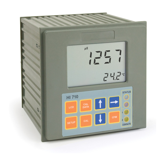
- Page 1 HI 700 / HI 710 Series Process, Panel-mounted, Microprocessor-based, Conductivity and TDS Controllers Instruction Manual...
-
Page 2: Table Of Contents
WARRANTY ......54 CE DECLARATION OF CONFORMITY ... 55 © 2001 Hanna Instruments All rights are reserved. Reproduction in whole or in part is prohibited without the written... -
Page 3: Preliminary Examination
• Four different EC working ranges (0 to 199.9 S; 0 to PRELIMINARY EXAMINATION 1999 S; 0 to 19.99mS; 0 to 199.9mS). Remove the instrument from the packing material and exam- • Four different TDS working ranges (0 to 100.0ppm; 0 to ine it carefully to make sure that no damage has occurred 1000ppm;... -
Page 4: Functional Description
REAR PANEL FUNCTIONAL DESCRIPTION FRONT PANEL 1. 6-pin RS485 terminal (HI 700222 and HI 710222 only) 2. Analog Output (HI 700221 and HI 710221 only) 3. Power Supply 4. Alarm Terminal 1. Liquid Crystal Display 5. Contact 2 - Second Dosing Terminal 2. -
Page 5: Specifications
SPECIFICATIONS INSTALLATION Ranges 0.0 to 199.9 μS, 0 to 1999 μS HI 700 and HI 710 0.00 to 19.99 mS, 0.0 to 199.9 mS series offer a multitude 0.0 to 100.0 ppm, 0 to 1000 ppm (HI 710* only) of possibilities, from 0.00 to 10.00 ppt, 0.0 to 100.0 ppt (HI 710* only) single and dual set- -10.0 to 100.0 °C... - Page 6 • Power Supply: Connect a 3-wire power cable If the Pt 100 has more than 2 wires, con- to the terminal strip, while paying attention nect the two wires of one end to pins 7 to the correct live (L), earth (PE) and neu- and 8 (pin 7 is an auxiliary input to com- tral (N) terminal connections.
-
Page 7: Setup Mode
• Then confirm the displayed digit with SETUP MODE and move to the next one. HI 700 and HI 710 offer a multitude of possibilities from ON/OFF or PID dosage to analog recorder output and from • When the whole password has been alarm to selftest features. - Page 8 • After confirmation, the selected parameter Code Valid Values Default is displayed. The user can scroll through the parameters by pressing CFM. 14 Relay 1 deviation (D1) 0.5 to 10% f.s. 1% f.s. 15 Relay 1 reset time 0.1 to 999.9 minutes 999.9 In order to directly set another param- eter, press SETUP again and enter the...
- Page 9 If M1= 3 then S1+D1 HA; Code Valid Values Default If M1= 4 then S1-D1 LA; 60 Current day 01 to 31 from RTC If M2= 1 then S2-H2 LA; If M2= 2 then S2+H2 HA; 61 Current month 01 to 12 from RTC If M2= 3 then S2+D2 HA;...
-
Page 10: Control Mode
An upper boundary is imposed for dosage time when relays CONTROL MODE are energized continuously, i.e. when relay works in ON/ OFF mode or also in PID mode but in the latter case only if The control mode is the normal operational mode for these the relay is always ON. - Page 11 control a low conductivity dosing pump. dition of low or high conductivity solution. An example of how the response overshoot can be improved with a proper rate action setting is depicted in the following graphic. Setpoint Setpoint + Hysteresis P .I.D. CONTROL MODE PID control is designed to eliminate the cycling associated with ON/OFF control in a rapid and steady way by means of RATE ACTION COMPENSATES FOR RAPID CHANGES...
- Page 12 The proportional action is set through the setup procedure as SIMPLE TUNING PROCEDURE “Deviation” in percent of full scale of the selected range. The following procedure uses a graphical technique of ana- Each setpoint has a selectable deviation: D1 for setpoint1 lyzing a process response curve to a step input.
- Page 13 ALARM RELAY This is an important feature since with most meters the alarm terminals close only when an abnormal situation arises, how- The alarm relay functions in the following manner: ever, due to line interruption, no alarm FS•C = NO (Normally Open) is sounded, causing extensive damage.
-
Page 14: Idle Mode
IDLE MODE ANALOG OUTPUT Idle mode is entered through setup code 2. HI 700221 and HI 710 221 models are provided with the analog output feature. During idle mode the device performs the same tasks as when it is in control mode except for the relays. The alarm relay is The output is isolated and can be a voltage or a current. -
Page 15: Rs 485 Communication
HI 92500 Windows ® compatible application soft- calibration at least once a year. ware offered by Hanna Instruments. Note The user-friendly HI 92500 offers a variety of features such Analog output resolution is 1.5‰ f.s. with 0.5% f.s. accu- as logging selected variables or plotting the recorded data. - Page 16 CONNECTIONS As additional feature, the controller is also provided with two pins (5V and 0V) in The connections for the 6-pin RS485 terminal provided (#1 order to apply the Fail Safe Open Line on page 7) are as follows: protection method. To avoid erroneous readings in Open-Line conditions, pull- up and pull-down resistors should be connected as shown.
- Page 17 Note If the controller is not in control or idle mode and the tem- Command Parameter Description perature reading is requested through the TMR command, the controller answers with the last acquired reading when it null Request calibration data was in control or idle mode. Request setup item NN Note After a recognized PWD command is received, the controller...
- Page 18 Note The controller answers to the GET command with the same control action is active, no alarm condition is present and data format explained in the SET command. controller setup is modified (must update controller setup for PC - GET command for setup items). Following are examples of answers: If asking for last calibration data and the controller was never 1) “03<STX>+01200<ETX>”...
-
Page 19: Calibration
Offset Calibration CALIBRATION • To perform the EC calibration enter The controller is factory calibrated for temperature as well as the calibration mode, by pressing for the analog input and outputs. CAL and entering the password. The user should periodically calibrate the instrument for EC •... - Page 20 • Press CFM to confirm the calibra- • Press LCD to display the current cell constant on the pri- tion point; if the reading is close to mary LCD (factory default value is 2.000 cm the selected solution, the meter stores the reading.
- Page 21 TEMPERATURE CALIBRATION ANALOG INPUT CALIBRATION The controller is factory calibrated for temperature. However, The analog input is already factory calibrated. However, the the user may also perform a one point temperature calibra- user may also perform a 2-point calibration at 4 and 20 mA. tion.
- Page 22 ANALOG OUTPUT CALIBRATION value shown on the secondary display (e.g. 4). In the meters where the analog output is available, this fea- • Wait for approximately 30 seconds (until the reading of the ture is factory calibrated through software. The user may also calibrator is stable).
-
Page 23: Last Calibration Data
LAST CALIBRATION DATA FAULT CONDITIONS AND SELFTEST PROCEDURES The meter can display the following last calibration data: The fault conditions below may be detected by the software: • Date • EEPROM data error; • Time • I2C internal bus failure; •... - Page 24 scrolling "Display test" message. EEPROM SELFTEST The EEPROM selftest procedure involves verifying the stored EEPROM checksum. If the checksum is correct the “Stored data good” message will be shown for a few seconds before exiting selftest procedure. The segments are lit for a few seconds and then switched off before exiting the selftest procedure.
-
Page 25: External Functions
WATCHDOG STARTUP When a dead loop condition is detected a reset is automati- cally invoked. During the automatic startup the Real Time Clock (RTC) is checked to see if a reset occurred since last software initial- The effectiveness of watchdog capability can be tested through ization. -
Page 26: Ec Values At Various Temperatures
EC VALUES AT VARIOUS TEMPERATURES PROBE MAINTENANCE Temperature has a significant effect on conductivity. Table Probe can be compensated for normal contamination by a below shows EC values at various temperatures for the Hanna process of recalibration. When calibration can no longer be calibration solutions. -
Page 27: Accessories
ACCESSORIES CONDUCTIVITY CALIBRATION SOLUTIONS OTHER ACCESSORIES HI 7030M 12880 μS/cm calibration solution, 230 mL bottle HI 7639 4-ring conductivity probe with built-in 3-wire Pt100 tempera- ture sensor and 5 m (16.5’) cable HI 7030L 12880 μS/cm calibration solution, 500 mL bottle HI 3011 4-ring conductivity probe with standard 1/2’’... -
Page 28: Warranty
If the repair is not covered by the warranty, you will be notified of the charges incurred. If the instrument is to be returned to Hanna Instruments, first obtain a Returned Goods Authorization number from the Cus- tomer Service department and then send it with shipping costs prepaid. - Page 29 TECHNICAL SERVICE CONTACTS Australia: Tel. (03) 9769.0666 • Fax (03) 9769.0699 China: Tel. (10) 88570068 • Fax (10) 88570060 Egypt: Tel. & Fax (02) 2758.683 Germany: Tel. (07851) 9129-0 • Fax (07851) 9129-99 Greece: Tel. (210) 823.5192 • Fax (210) 884.0210 Indonesia: Tel.
Need help?
Do you have a question about the HI 710 Series and is the answer not in the manual?
Questions and answers