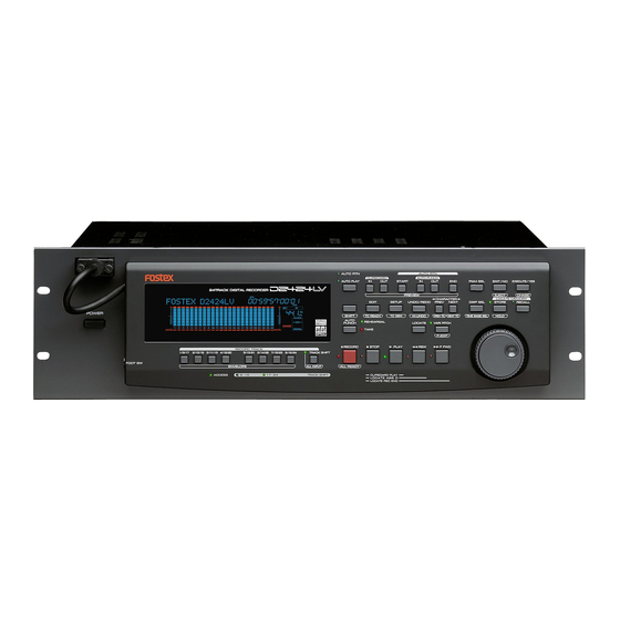
Fostex D2424LV Reference Manual
24 track digital recorder
Hide thumbs
Also See for D2424LV:
- Quick operation manual (28 pages) ,
- Brochure (5 pages) ,
- Specifications (2 pages)
Table of Contents
Advertisement
Quick Links
Model
POWER
FOOT SW
Thank you for purchasing the Fostex D2424LV.
The D2424LV is a digital recorder using a 3.5 inch E-IDE hard disk recording media for recording/
playback/editing in 24 real tracks plus 32 additional tracks.
In addition to non-compression recording at quantization 16 bit/44.1kHz or 48kHz, 24 bit/44.1kHz
or 48kHz, 24 bit/88.2kHz or 96kHz, the D2424LV is also equipped with adat input/output (by
switching from S/P DIF).
Besides analog simultaneous record/playback, because it also complies with digital recording (S/P
DIF or adat) using DATA input/output and simultaneous recording of analog input plus digital input
(S/P DIF or adat), a full digital recording system can be built by combining the D2424LV with various
digital mixers.
In regards to save/load of song data, in addition to using adat digital signals and S/P DIF digital
signals, high speed backup of FDMS-3 Ver. 3.0/WAV file through the standard feature SCSI connec-
tor, is also possible.
Furthermore, by installing an optional Model 9044 (BAY+CADDY), an E-IDE hard disk for backup or
the optional Model 9046 (DVD-RAM drive) can be installed enabling high speed backup of FDMS-3
Ver. 3.0/WAV files.
For optional units, Model 8346 TC/SYNC card is available and these will also comply to phasing of
the standard feature WORD clock and also phasing against slave control by external LTC and VIDEO
reference signals.
Please carefully read through this manual together with the separate " Quick Operation Guide " for long
and satisfying operation of this equipment.
Reference Manual
24 Track Digital Recorder
24TRACK DIGITAL RECORDER
RECORD TRACK
1/9/17
2/10/18
3/11/19
4/12/20
5/13/21
6/14/22
7/15/23
8/16/24
ENVELOPE
ACCESS
9-16
17-24
Introduction
AUTO RTN
AUTO RTN
CLIPBOARD
AUTO PUNCH
AUTO PLAY
START
IN
OUT
IN
OUT
PREVIEW
CHARACTER
EDIT
SETUP
UNDO/REDO
PREV
SHIFT
TC READY
TC GEN
M.UNDO
PREV TC
AUTO
REHEARSAL
24bit
LOCATE
VARI PITCH
PUNCH
96kHz
TAKE
OPTICAL
RECORD
STOP
PLAY
REW
TRACK SHIFT
ALL INPUT
ALL READY
TRACK SHIFT
CLIPBOARD PLAY
LOCATE ABS 0
LOCATE REC END
8288 488 000
PGM SEL
EXIT/NO
EXECUTE/YES
END
EJECT
CHASE
LOCATE MEMORY
NEXT
DISP SEL
STORE
RECALL
NEXT TC
TIME BASE SEL
HOLD
P.EDIT
F FWD
Advertisement
Chapters
Table of Contents

Related Manuals for Fostex D2424LV


Summary of Contents for Fostex D2424LV
- Page 1 LOCATE ABS 0 LOCATE REC END Introduction Thank you for purchasing the Fostex D2424LV. The D2424LV is a digital recorder using a 3.5 inch E-IDE hard disk recording media for recording/ playback/editing in 24 real tracks plus 32 additional tracks.
-
Page 2: Safety Instructions
Model D2424LV Reference Manual (Safety Instruction/Contents) CAUTION: CAUTION TO PREVENT ELECTRIC SHOCK, MATCH WIDE BLADE OF RISK OF ELECTRIC SHOCK PLUG TO WIDE SLOT, FULLY INSERT. DO NOT OPEN ATTENTION: POUR EVITER LES CHOCS ELECTRIQUES, INTRODUIRE CAUTION: TO REDUCE THE RISK OF ELECTRIC SHOCK,... -
Page 3: Table Of Contents
Model D2424LV Reference Manual (Safety Instruction/Contents) Contents Main Features................................7 Precautions..................................8 Names and Functions........................9 Front panel section..................................10 Detachable controller section..............................11 Rear panel section..................................18 Display section.....................................19 Display shown when the power is turned on....................19 Preset display..............................20 Switching the display using the [DISP SEL] key.....................21 Switching the time base display using the [SHIFT] key and [DISP SEL] key..........21... - Page 4 Model D2424LV Reference Manual (Safety Instruction/Contents) Recording Digital data........................45 Digital recording from an external digital device........................45 Digital recording to an external digital device........................47 Connecting a Digital Mixer................................48 Recording to a Metronome Sound.....................49 Preparation......................................49 Recording to a metronome sound............................49 Storing a Locate Point........................51 Storing and editing the locate points to the memory keys....................52...
- Page 5 Model D2424LV Reference Manual (Safety Instruction/Contents) Erase........................................72 Storing the edit points..........................72 Checking and adjusting the edit points......................73 Executing Erase...................................73 Single undo/redo Erase............................73 Track Exchange...................................74 Executing track exchange..........................74 Registering the Track name...............................76 MIDI Sync Function........................77 MIDI clock sync system................................77 Connecting external equipment........................77 Setup of the recorder............................78...
- Page 6 Model D2424LV Reference Manual (Safety Instruction/Contents) Changing the Initial Setting (SETUP mode)................107 Selecting SETUP menu................................108 Time Signature Setting................................109 Storing a time signature..........................109 Modifying (or deleting) stored time signatures..................110 Clearing all time signature and tempo settings..................110 Changing the bar at ABS "0" of the time base.....................110 Setting a Tempo..................................111...
-
Page 7: Main Features
Model D2424LV Reference Manual (Main features/Precautions) Main features The unit’s recorder section uses a recording format called FDMS-3 Ver 3.0 (Fostex Disk Management System- 3). It uses an E-IDE hard disk as the recording media. • Save/load of FDMS-3 or WAV file is possible by •... -
Page 8: Precautions
About damage section is stopped. Especially, never attempt to turn off the power to • FOSTEX is not responsible for any “direct damage” the recorder while the hard disk is accessing data or “indirect damage” caused by using the recorder. -
Page 9: Names And Functions
Model D2424LV Reference Manual (Names and Functions) Names and Functions Front panel-1 AUTO RTN AUTO RTN CLIPBOARD AUTO PUNCH AUTO PLAY START PGM SEL EXIT/NO EXECUTE/YES 24TRACK DIGITAL RECORDER PREVIEW EJECT CHASE CHARACTER LOCATE MEMORY EDIT SETUP DISP SEL STORE... -
Page 10: Front Panel Section
Model D2424LV Reference Manual (Names and Functions) Front Panel section 24TRACK DIGITAL RECORDER POWER 24bit/96kHz 1. Detachable remote controller connector * Refer to “ Quick operation Guide ” for more information The detachable remote controller is connected here. on how to replace the removable hard disk cartridge. -
Page 11: Detachable Controller Section
Model D2424LV Reference Manual (Names and Functions) Detachable Controller section 4 5 6 7 8 9 10 14 15 AUTO RTN AUTO RTN CLIPBOARD AUTO PUNCH AUTO PLAY PGM SEL EXIT/NO START EXECUTE/YES 24TRACK DIGITAL RECORDER PREVIEW EJECT CHASE CHARACTER... - Page 12 Model D2424LV Reference Manual (Names and Functions) Auto Repeat mode: * Refer to page “ 40 ” for more information about Auto This mode is a combination of Auto Play and Auto Return, Punch In/Out recording. and plays back the part between the START and END points * Refer to page “...
- Page 13 Model D2424LV Reference Manual (Names and Functions) 10. Auto Return End key 12. Program select key [AUTO RTN END/PREVIEW] [PGM SEL] This key is used to store and recall the end point This key has the following two functions depending (AUTO RTN END point) for the Auto Return or Auto on the setup condition of "Chain Play?"...
- Page 14 Model D2424LV Reference Manual (Names and Functions) 16. Recall key [RECALL] * Refer to page “ 51 ” for more information about the editing the memory data. This is pressed to call out the time figure (or bar/ * Refer to page “ 107 ” for more information about SETUP beat/clk figure) data stored in locate number (0- mode.
- Page 15 Model D2424LV Reference Manual (Names and Functions) 22. Locate key 25. Play button [LOCATE] [PLAY] Use this key to start to start the LOCATE feature. Pressing this button will cause the recorder to play Pressing this key after a memory key (CLIPBOARD back.
- Page 16 Model D2424LV Reference Manual (Names and Functions) *2 Locate ABS 0: 29. Record button [RECORD] The recorder will locate the top of the selected Program Pressing only this button places the readied tracks (ABS TIME: 00M: 00S: 00F). into input monitoring status. Pressing this button again will reset the tracks to playback monitoring.
-
Page 17: Meter Display
Model D2424LV Reference Manual (Names and Functions) <Note> <Note> If a correct value is not stored, pressing the [AUTO Ejecting or removing the backup SCSI disk is only PUNCH] key will not enable the function, and the possible when the drive is set to "SCSI*" via the SETUP message “... -
Page 18: Rear Panel Section
[REMOTE INPUT] connector is output here. This is connected to the second recorder REMOTE <Note> INPUT when controlling a multiple number of Installation of the option must be done by our Fostex recorders. Service Station. For details, please inquire at your nearest Fostex Service Station. -
Page 19: Display Section
Model D2424LV Reference Manual (Names and Functions) 12. SCSI connector [SCSI] <for song data> (Connector: half-pitch 50-pin) [DATA OUTPUT] 1-8 must be used (the other connectors Connect a backup SCSI device to SAVE/LOAD data. do not feed song data). Up to one SCSI devices can be connected to the SCSI <for S/P DIF digital signals>... -
Page 20: Preset Display
Model D2424LV Reference Manual (Names and Functions) 2. Preset Display The display below shows all preset items for explanation purpose. 35 dot message display This display indicates the ABS time, MTC time value or bar/beat/clock value, and a parameter name in the SETUP mode. -
Page 21: Switching The Display Using The [Disp Sel] Key
Model D2424LV Reference Manual (Names and Functions) 3. Switching the display using the [DISP SEL] key. ABS time base Let’s assume that you turned off the power while the time display was using a time base of “ABS,” and then you turned the power on again. The... -
Page 22: Warning Display
Model D2424LV Reference Manual (Names and Functions) You can select the desired Program from the • Display of void: This is displayed if you attempt some sort of process for already setup Programs by rotating the Jog dial which the optional Model 8346 TC/SYNC card is while the Program number and “SURE?”... - Page 23 [EXECUTE/YES] key to format the disk. (All audio and other data on the disk will be lost.) • Disk error indication: This disk cannot be read. CLOCK • Action to take: Contact the Fostex service station as soon as possible.
-
Page 24: Before Starting
Model D2424LV Reference Manual (Before Starting) Before Starting This chapter describes some basic items that you need to know before you start operating the recorder. All users, including those who are familiar with using tape-based multitrackers and those who are new to multitrackers, should read this chapter thoroughly to understand the functions of the recorder. -
Page 25: Recording Method And Remain Indicator
Model D2424LV Reference Manual (Before Starting) Recording method and REMAIN indicator Recording method REMAIN indicator The REMAIN indicator displays available The recorder uses a E-IDE hard disk instead of recording time expressed in time value (ABS or a cassette tape. You can start recording sound... -
Page 26: Managing Songs By Program Change Function
Model D2424LV Reference Manual (Before Starting) Managing songs by Program Change function The recorder feature a Program Select function, which enables you to set up to 99 Programs on the disk. When you format a disk, one Program is automatically created on the disk. You may create more Programs, if necessary. -
Page 27: Real Tracks And Additional Tracks
Model D2424LV Reference Manual (Before Starting) Real tracks and Additional tracks The D2424LV contains, in addition to 24 real tracks that can be recorded/played back/edited in real time as one program, 32 additional tracks (In the current drive formatted at 96kHz/24bits or 88.2kHz/24 bits, it will be 8 real tracks + 48 additional tracks.). -
Page 28: Input Monitoring And Playback Monitoring
Model D2424LV Reference Manual (Before Starting) Input monitoring and playback monitoring There are two methods for monitoring track sound (only on the Real tracks): input monitoring and playback monitoring. They are defined as follows: Input monitoring Input monitoring means to listen to what is being input to the recorder so that you can verify sound quality and etc. -
Page 29: Audio File And Event
Model D2424LV Reference Manual (Before Starting) Audio file and event <About an audio file> During recording, the recorder consecutively records an independent audio file (recorded area) in each track of each Program. However, you can record data on the recorder at any point within 24 hours of ABS time, and you can intentionally create silence between two audio files. - Page 30 Model D2424LV Reference Manual (Before Starting) Recorded Area 0 File Audio File 1 Audio File 2 Audio File 4 Audio File 6 0 File Audio File 3 Audio File 5 Event Number This is because when you perform a copy & paste, move & paste, or Auto Punch In/Out, the event is split at the edit point.
-
Page 31: Formatting And Optimizing Disks
Time required for formatting is shorter, but any bad sectors would not be detected. Quick Format Select this format type when you format a brand new disk for which Fostex has confirmed Format Type quality operation. You can select this format type only when you format a new disk or reformat a disk previously formatted with Quick Format. -
Page 32: Formatting A Brand New Hard Disk (Current Drive)
Model D2424LV Reference Manual (Formatting and Optimizing Disks) <Available recording time after formatting> A greater sampling frequency will reduce the available recording time/space after formatting. Under the same sampling frequency setting, the greater quantization (bit number) reduces the available recording time. -
Page 33: Reformatting The Current Drive Or Newly Formatting The Backup Drive
Model D2424LV Reference Manual (Formatting and Optimizing Disks) Re-Formatting the Current Drive or Newly Formatting the Backup Drive Follow procedures below to re-format the current drive or newly format the E-IDE hard disk for backup. <Note> You cannot use the recorder to format a back-up E-IDE hard disk for saving and loading WAV files. First, format the disk for WAV files using a computer (PC/AT). -
Page 34: Optimizing The Disk
Model D2424LV Reference Manual (Formatting and Optimizing Disks) 3.Use the Jog dial to select flashing “SCSI” (or <Bit resolution> “IDE2”) and press the [EXECUTE/YES] key. The same figures in quantization of the current drive When formatting the disk of the SCSI drive connected to will be displayed for quantization of the backup for- the SCSI connector, select "SCSI"... -
Page 35: Handling Programs
Model D2424LV Reference Manual (Handling Programs) Handling Programs This chapter explains how to handle Programs. It covers the following topics: 1. Creating a new Program 2. Using a Program Change function 3. Duplicating a Program 4. Deleting a Program 5. Editing a Program title 6. -
Page 36: Duplicating A Program
Model D2424LV Reference Manual (Handling Programs) 6. When you finish entering the title, press the To enter a title: [EXECUTE/YES] key. • Turn the Jog dial, or pressing the [NEXT] key and Program 2 (PGM 02) and its title are set. -
Page 37: Using A Program Change Function
Model D2424LV Reference Manual (Handling Programs) Using a Program Change function If multiple Programs exist on the disk, you need to select a Program to record, play, or edit. This section describes how to select a Program. <Notes> • You cannot use the Program Change function when the recorder is in SETUP mode. -
Page 38: Editing A Program Title
Model D2424LV Reference Manual (Handling Programs) 1. Press the [SETUP] key while the recorder is Flashing stopped, to put the system in the SETUP mode. SETUP SURE? 2. Turn the Jog dial to select the first hierarchy of the CLOCK “Delete PGM ** ?”... -
Page 39: Changing The Program Fs
Prerecorded data cannot be guaranteed. • Do not copy & paste track data between programs with different FS. Fostex does not guarantee song data which is created using the copy & paste function between programs with different FS. 1. Press the [SETUP] key while the recorder is <Note>... -
Page 40: Punch In/Out
Model D2424LV Reference Manual (Punch In/Out) Punch In/Out What is Punch In/Out recording? Punch In/Out recording enables you to record over previously-recorded parts. See the diagram below. For example, using the Punch In/Out function allows you to change an unsatisfactory guitar solo. The D2424LV offers two types of Punch In/Out functions. One is called Auto Punch In/Out, in which you automatically re-record a specified part. -
Page 41: Rehearsing Auto Punch In/Out
Model D2424LV Reference Manual (Punch In/Out) 4. Play the guitar accompanying the playback sound Rehearsing Auto Punch In/Out recording from tracks 1 - 8 for rehearsal, while adjusting the recording level. In Rehearsal mode, the READY track assumes You will hear the guitar performance between the Auto input monitoring mode between the Auto Punch In and Out points. -
Page 42: Auto Punch In/Out Take
Model D2424LV Reference Manual (Punch In/Out) 5. When you finish recording, press the [STOP] Auto Punch In/Out Take button. After you are satisfied with your rehearsal, you 6. Play track 3 to check the result of the Auto Punch can proceed to an actual take of Auto Punch In/Out operation. -
Page 43: Manual Punch In/Out
Model D2424LV Reference Manual (Punch In/Out) Manual Punch In/Out This section explains how to perform Manual Punch In/Out using a foot switch (optional Model 8051). You do not need to specify the Punch In/Out points. Instead, you press the foot switch at the Punch In/Out point. -
Page 44: Manual Punch In/Out Take
Model D2424LV Reference Manual (Punch In/Out) Manual Punch In/Out take <Hint> You can use the [PLAY] button and the [RECORD] You can proceed to record if you are satisfied button, instead of using the foot switch. with the recording level, foot switch timing, and Follow the steps below. -
Page 45: Recording Digital Data
Model D2424LV Reference Manual (Recording Digital Data) Recording Digital Data Digital recording from an external digital device In addition to multirecording by connection to a digital mixer as explained in the separate “Quick Operation Guide” manual, the following explains the direct digital recording method by connection to external digital equipment (CD, MD, DAT, adat, etc.). - Page 46 Model D2424LV Reference Manual (Recording Digital Data) • Selecting a recording Program <Notes> • Do not connect or disconnect the optical cable to 1. If you already have multiple Programs, select the the [DATA INPUT] connector when digital input is desired Program using the Program Select assigned.
-
Page 47: Digital Recording To An External Digital Device
Model D2424LV Reference Manual (Recording Digital Data) [Clock Sel ?] Auto Video Word setting [D. in ?] setting When receiving word clock When receiving word clock from WORD IN, the recorder from WORD IN, the recorder Regardless of receiving or not... -
Page 48: Connecting A Digital Mixer
* See page “ 119 ” for more information on the “D. out?” * If the connected external device has only a COAXIAL menu. (RCA pin) jack for digital input, use an optional Fostex COP-1/96k (optical/coaxial converter). When you finish setting the parameters in Setup mode, press the [EXIT/NO] key or the [STOP] button •... -
Page 49: Recording To A Metronome Sound
Model D2424LV Reference Manual (Recording to a Metronome Sound) Recording to a Metronome Sound This chapter explains how to record your performance while you are playing an instrument accompanied by a metronome based on the time signature and tempo specified in the Tempo Map. -
Page 50: Starting Recording
Model D2424LV Reference Manual (Recording to a Metronome Sound) • Checking the recorded sound • Checking the metronome sound 1. Press the [DISP SEL] key while holding down the 13. Turn OFF the ready track [RECORD TRACK] select [SHIFT] key to switch the time base in advance to key . -
Page 51: Storing A Locate Point
Model D2424LV Reference Manual (Storing a Locate Point (Edit Point) Storing a Locate Point (Edit Point) You can store specific individual time data (time, bar/beat/clock) in each memory key (*). The time data stored is used as an “Editing Point” to execute “Locate Point” or Auto Punch In/Out, Copy & Paste, Move &... -
Page 52: Storing And Editing The Locate Points To The Memory Keys
Model D2424LV Reference Manual (Storing a Locate Point (Edit Point) Storing and editing the locate points to the memory keys • Select the desired Time Base using the [DISP SEL] key and [SHIFT] key an if you wish to use a Time Base other ABS. -
Page 53: Storing And Editing Locate Key
Model D2424LV Reference Manual (Storing a Locate Point (Edit Point) 1.While the recorder is stopped, press the memory • You can store the edited data in a memory key other key that stores the data you wish to edit. than the one you pressed when you recalled the data. -
Page 54: Edit And Re-Store Data That Is Already Stored
Model D2424LV Reference Manual (Storing a Locate Point (Edit Point) 3.Select the LOCATE number desired using the Jog <Please remember this!> dial. • If you set “BAR/BEAT Resolution mode” in SETUP LOCATE number from 00-99 are selectable. However, mode to ON, the recorder will round off the CLK value select a number other then 00. -
Page 55: Locate Function
Model D2424LV Reference Manual (Locate Function) Locate Function The recorder swiftly locates (it moves the current location of the recorder section) the desired point when necessary. Locate include edit points (in ABS time, MTC time, or in bar/beat/clock) that are stored for the Copy, Move, Paste, Erase, or Auto Punch In/Out operations. -
Page 56: Auto Play Function
Model D2424LV Reference Manual (Locate Function) Auto Play function The Auto Play function allows the recorder to start play back automatically from the located point. AUTO PLAY mode should be turned on before you execute the Direct Locate function described above. -
Page 57: Auto Repeat Function
Model D2424LV Reference Manual (Locate Function) Auto Repeat function The Auto Repeat function allows the recorder to repeat playback up to the AUTO RTN END point, automatically locate the AUTO RTN START point, then play up to the AUTO RTN END point until you cancel the function by pressing the STOP button. -
Page 58: Chain Play Function
Model D2424LV Reference Manual (Chain Play function) Chain Play function “Chain play” functions to playback, in any order, the tunes recorded on a multiple number of programs. There are three modes of chain play and each operates as shown below. -
Page 59: Setup Of The Chain Play List
Model D2424LV Reference Manual (Chain Play function) Setup of the Chain Play List The chain play list is setup via the “Chain Play List?” menu in the SETUP mode. The following procedure is based on the assumption that a multiple number of programs are in the current drive and that a tune is recorded in each program. -
Page 60: Setup Of The Chain Play Mode
Model D2424LV Reference Manual (Chain Play function) Setup of the Chain Play Mode Upon setup of the previous “Chain Play List,” select the desired mode in the “Chain Play MD?” (Setup of the chain play mode) menu in the same SETUP mode. -
Page 61: Specify The Program And Execute Chain Play
Model D2424LV Reference Manual (Chain Play function) Specify the Program and Execute Chain Play Specify at random a program set in the chain play list and execute chain play from the program specified. This operation can be executed only when the “Chain Play?” menu is set in other than “Off.”... -
Page 62: Cue & Review Function
Model D2424LV Reference Manual (Cue & Review Function) Cue & Review Function This chapter explains how to use the “Cue & Review” function with the [REWIND] button, the [F FWD] button, and the Shuttle dial, and also explains “Digital Scrubbing” with the envelope function. - Page 63 Model D2424LV Reference Manual (Cue & Review Function) 1. While the recorder section is stopped, depress the [SHIFT] key and then press the [RECORD TRACK] select key of the desired record track. This turns ON the envelope function. The envelope indication of the selected track will appear on the display.
-
Page 64: Preview Function
Model D2424LV Reference Manual (Preview Function) Preview Function The preview function enables you to repeatedly audition the rise (fade in) or the fall (fade out) of the sound data at a locate point (edit point) that is stored in the [AUTO PUNCH IN/OUT], [AUTO RTN START/END], or [CLIPBOARD IN/OUT] key. -
Page 65: Executing The Preview Function
Model D2424LV Reference Manual (Preview Function) Executing the Preview function 1. Press the desired memory key while holding down the 2. Adjust the monitor sound of the selected track so that [SHIFT] key when the recorder is stopped. it can be monitored on the mixer. -
Page 66: Multiple Undo Function
Model D2424LV Reference Manual (Multiple Undo Function) Multiple Undo Function To undo recordings or edits, you can use the Multiple Undo (Time Jump) function (explained in this section) as well as the Single Undo/Redo function (explained in the Quick Operation Guide and the “Punch in/out”... -
Page 67: Using The Multiple Undo Function
Model D2424LV Reference Manual (Multiple Undo Function) Using the Multiple Undo function 2.Use the Jog dial or the [NEXT] key and [PREV] 1.While the recorder is stopped, press and hold key to select the desired date and time, and press down the [SHIFT] key and press the [UNDO/REDO] the [EXECUTE/YES] key. -
Page 68: Editing Tracks
Model D2424LV Reference Manual (Editing Tracks) Editing Tracks The recorder features speedy, nonlinear, nondestructive editing of independent audio tracks because it uses a 3.5 inch E-IDE hard disk. The following four editing functions allow “Editing of Independent Audio Tracks.” Copy & Paste... -
Page 69: Storing The Edit Point
Model D2424LV Reference Manual (Editing Tracks) • Executing Copy (or Move) <Notes> • The data on the clipboard will be replaced by new data each time you execute the COPY or MOVE. <Note> You can carry out the copy (or move) function only •... -
Page 70: Executing Paste
Model D2424LV Reference Manual (Editing Tracks) This number will count down as the paste operation • Checking the clipboard data proceeds. When the paste operation is complete, the flashing “Copy Paste” (or “Move Paste”) lights up • Hold down the [STOP] button and press the [PLAY] continuously, and “COMPLETED !”... -
Page 71: Copy & Paste Between Programs
Model D2424LV Reference Manual (Editing Tracks) • Copy & Paste between programs • Checking the clipboard data Copy & Paste between programs can be performed Data copied to the clipboard can be confirmed even using the procedures below in the same manner as after switching the program by the above procedure. -
Page 72: Erase
Model D2424LV Reference Manual (Editing Tracks) Erase There are two methods for erasing data. Understand the difference between these methods before you use the Erase function. • If multiple Programs are set on the disk, first select the desired Program. Do not select another Program, or select another sampling rate until you finish the erase operation. -
Page 73: Checking And Adjusting The Edit Points
Model D2424LV Reference Manual (Editing Tracks) • Checking and adjusting the edit points <Check Points!> • To erase the data in its entirety from the tracks, After you store the edit points, you can check them you can also use the Program Delete function to on the display by pressing the corresponding keys. -
Page 74: Track Exchange
Model D2424LV Reference Manual (Editing Tracks) Track Exchange "Track exchange" is the function that exchanges tracks -- all real tracks and all additional tracks-- currently in the programs, in mono track units or in multiple track (Stereo pair 2 tracks; 8 track units) units. - Page 75 Model D2424LV Reference Manual (Editing Tracks) • Exchanging in group track units • Exchange in mono track units 1. By pressing the [EXECUTE/YES] key after “TRK 1. Upon display of the previously mentioned "TRK Exch. Group?” is displayed, the display will change Exch.Mono?,"...
-
Page 76: Registering The Track Name
Model D2424LV Reference Manual (Editing Tracks) Registering the Track name Any type of track name can be registered or edited for each real track/additional track. In general, after the current drive is formatted, a "Temporary title"("#TRACK 1," etc.) is automati- cally registered for all tracks. -
Page 77: Midi Sync Function
Model D2424LV Reference Manual (MIDI Sync Function) MIDI Sync Function The following are examples concerning general types of systems using MIDI related functions contained in the recorder. MIDI clock sync system By setting any desired meter at any desired point of the programmable tempo map contained in the recorder, and by output of a MIDI clock and song position pointer according to the setting, a hardware type MIDI sequencer can be synchronized as a MIDI clock slave. -
Page 78: Setup Of The Recorder
Model D2424LV Reference Manual (MIDI Sync Function) • Setup of the D2424LV 1. Because the MIDI clock and song position pointer will be output from the recorder, set the SETUP mode “MIDI sync signal output setting” to “CLK.” * Initial setting: * Permissible setting: CLK (MIDI clock and song position pointer:”CLK”) -
Page 79: Executing Of Recording
In regards to the corresponding content for MMC, refer to the “MMC list” on page “134” and on the Fostex System Exclusive Message, the “Fostex Exclusive List” on page “135.” * Set the recorder in the initial state. -
Page 80: Setup To External Equipment
Refer to page “ 114 ”, SETUP mode “MTC Frame rate setting” for operating procedure and details. 5. Set to the same figure as the sequence software MMC device number (and Fostex System Exclusive Message device number) by the SETUP mode “MIDI device ID setting.”... -
Page 81: Confirming Mtc Sync/Mmc
Model D2424LV Reference Manual (MIDI Sync Function) * Initial setting: * Permissible setup ID: 00 ~ 99 * This item will be the setting common to all programs. * This setting cannot be saved/loaded as song data. * This setting will be held even though power is switched OFF. -
Page 82: Multitrack System By The Slave Mode
Model D2424LV Reference Manual (MIDI Sync Function) Multitrack system by the slave mode An example of how to make a multitrack system by interconnecting three recorders in a slave mode function, will be explained in the following. * Initialize the recorder. -
Page 83: Setup Of The Recorder (#2) And (#3):
Model D2424LV Reference Manual (MIDI Sync Function) 3. With the SETUP mode “MTC offset mode setting,” whether the MTC offset time will be output (ABS) at the ABS 00H 00M 00S 00F 00SF point or at the 001BAR 1BEAT 00CLK (bar/signature) point of the tempo map, is selected. -
Page 84: Check Chase Lock
Model D2424LV Reference Manual (MIDI Sync Function) <Note> After this setup, check the following in the recorder (#2) and (#3). • Blinking of “ CHASE ” in the display: This will change to constant lit upon completing chase lock in lateroperation. -
Page 85: External Midi Equipment Sync System By The Slave Mode
Model D2424LV Reference Manual (MIDI Sync Function) External MIDI equipment sync system by the slave mode Up to this point, synchronization with external MIDI equipment has been explained with the recorder as the master and MIDI equipment as the slave but depending on the slave mode setting, the MIDI equipment can be set as the master and the recorder as the slave. -
Page 86: Confirming Chase Lock
Model D2424LV Reference Manual (MIDI Sync Function) 5. Set slave type to “Vari” by the SETUP mode “Slave type setting.” Refer to page “ 117 ”, SETUP mode “Slave type setting” for operating procedure and details. 6. Press the [DISP SEL] key while holding down the [SHIFT] key, to change the time base display to MTC. -
Page 87: Saving And Loading Song Data
Model D2424LV Reference Manual (Saving and Loading Song Data) Saving and Loading Song Data The recorder allows you to select the data (audio data and Setup data) from a current Program and save it to a DAT machine as an S/PDIF digital signal or to an adat machine as an adat digital signal, or save it to a SCSI device. - Page 88 The headphone jack provided in the optional Model 9046 cannot be used. Do not plug in the headphone. Installation of Model 9046 must be done by the Fostex Service Department. After purchasing this unit, please request the nearest Fostex Service Station.
-
Page 89: Saving The Data Using A Adat Or S/P Dif Digital Signal
Model D2424LV Reference Manual (Saving and Loading Song Data) Saving the data using a adat or S/P DIF digital signal S/P DIF digital signal (or adat digital signal) from the [DATA OUTPUT] connector of the recorder is saved. * Restore the initial settings on the recorder. - Page 90 Model D2424LV Reference Manual (Saving and Loading Song Data) 1.Press the [SETUP] key. 7.Press the [EXECUTE/YES] key again. The recorder enters Setup mode. “Save Trk ? 1-24” (“1” is flashing) appears on the display and you can select tracks to save.
-
Page 91: Loading The Data Using A Adat Or S/P Dif Digital Signal
Model D2424LV Reference Manual (Saving and Loading Song Data) Loading the data using a adat or S/P DIF digital signal Load the data by S/P DIF digital signals (or adat digital signals) from the [DATA INPUT] connector of the recorder. - Page 92 Model D2424LV Reference Manual (Saving and Loading Song Data) 1.Press the [SETUP] key. 7.Select the desired track range using the Jog dial. The recorder will enter the Setup mode. You can select 1, 9, 17, 25, 33, 41 and 49 of the points that are flashing (left).
-
Page 93: Saving The Deta Using Scsi
Model D2424LV Reference Manual (Saving and Loading Song Data) Saving the data using SCSI This procedure will SAVE/LOAD using a removable SCSI drive disk (zip, MO, DVD-RAM etc.) that is a backup disk. In save/load using SCSI, the program can be selected separately or in whole. -
Page 94: Formatting A Scsi Disk
Model D2424LV Reference Manual (Saving and Loading Song Data) Formatting a SCSI disk An unformatted disk or a disk used with the computer can also be used. Check to see that the data on the disk is no longer necessary prior to formatting a disk that was previously used with the computer. Once formatting is started it cannot be stopped. -
Page 95: Saving Data Of An Individual Program
Model D2424LV Reference Manual (Saving and Loading Song Data) Saving data of an individual Program When saving with a SCSI disk it is possible to save each program or all programs. • Output format available : adat, SPDIF, SCSI, IDE2 •... - Page 96 Model D2424LV Reference Manual (Saving and Loading Song Data) 5. Press the [EXECUTE/YES] key. 6.Press the [STOP] button or the [EXIT/NO] key to The recorder performs the save operation differently quit the Setup mode. depending on the selected Program. <Note>...
-
Page 97: Saving The Data Using Scsi
Model D2424LV Reference Manual (Saving and Loading Song Data) <Notes on saving all programs in several disks> In the previous procedure, when the left and right numbers were different such as "(05/08)" in the "(**/**)" display of "Save All (**/**)," it could not be saved in one disk, and indicated that a multiple number of disks were required. -
Page 98: Load The Data Saved On Several Removable Disks
Model D2424LV Reference Manual (Saving and Loading Song Data) Loading data saved on several removable disks As an example here, we will load the data of a Program saved onto two removable disks. 1.Insert the first disk (Disk-1) into the SCSI device. -
Page 99: Loading The Data Using Ide2 (E-Ide Hard Disk Or Optional Dvd-Ram)
DVD-RAM drive (Model 9046) for backup purposes. With this setup it becomes possible to save/load files in WAV (RIFF WAVE file format, hereafter WAV) described later, or save/load in FDMS-3 V3.0 (Fostex Disk Management System-3) format described earlier. <Precautions> • This model can only save/load in IDE2 (E-IDE or DVD-RAM) FDMS-3 Ver3.0 format. When using an IDE2 to save/load WAV files, priority format it in FAT16 DOS on another PC. -
Page 100: Loading Data Of Fdms-3 Version 3.0
Model D2424LV Reference Manual (Saving and Loading Song Data) If, for example, you choose 01 as illustrated in the case Flashing above, you can save all programs. If you select 03 you SETUP SURE? can save the programs from program 03 to the last program. -
Page 101: Save/Load By "Wav" File
SAVE/LOAD by “WAV” file In addition to save/load by the aforementioned FDMS-3 (Fostex Disk Management System-3), save/ load to a DOS formatted disc by using WAV (RIFF WAVE file format, hereafter called WAV) file is possible. In the same way as the aforementioned “Save/Load by FDMS-3,” it is possible not only to save data from this recorder but also to read data by this recorder;... -
Page 102: Saving Of "Wav" Files
Model D2424LV Reference Manual (Saving and Loading Song Data) Saving of “WAV” files A WAV file is saved by the following procedure. Before proceeding to save, make sure a DOS formatted disk in FAT 16 is set in the SCSI equipment. The following explains the procedures for using a backup disk after it had been formatted. - Page 103 Model D2424LV Reference Manual (Saving and Loading Song Data) If "05-05" is selected: “WAV” FILE WHICH WAS SAVED The Flashing "05 05" will change to flashing only of the right "05". Flashing • Composition of WAV file A WAV file on the backup disk is made, one file to one SETUP track in the root directory, for a total of 24 files.
-
Page 104: Loading Wav Files
Model D2424LV Reference Manual (Saving and Loading Song Data) "Title" & "###MB" display: < Notes> In this instance, the selected WAV file on the backup • If you attempt to save a WAV file with the same file disk is deleted and there is now enough capacity to make name as one already existing on the backup disk, a WAV file. - Page 105 Model D2424LV Reference Manual (Saving and Loading Song Data) Flashing <Notes> • If there is insufficient capacity in the current drive SETUP to load a WAV file, the capacity will be indicated in minus as "-###". In such a case, select a program of a the right size or...
-
Page 106: Special Loading Method When Using A Computer
Model D2424LV Reference Manual (Saving and Loading Song Data) << Special loading method when using a computer >> < Note> WAV files which can be saved/loaded by this recorder must have file names written as “ ******##.WAV. ” Other file names cannot be acknowledged by this recorder. -
Page 107: Changing The Initial Setting (Setup Mode)
Model D2424LV Reference Manual (Changing the Initial Settings <SETUP mode>) Changing the Initial Settings (SETUP mode) The SETUP mode offers the Changing the initial settings menus to configure the operating environment of the recorder, a “Check” menu that enables you to check the number of events of each track and the “Execution”... -
Page 108: Selecting Setup Menu
Model D2424LV Reference Manual (Changing the Initial Settings <SETUP mode>) Selecting SETUP menu Follow the steps below to select the desired SETUP menu in SETUP mode. 1. While the recorder is stopped, press the [SETUP] The title of the SETUP menu appears. You can select a different menu via the Jog dial. -
Page 109: Time Signature Setting
Model D2424LV Reference Manual (Changing the Initial Settings <SETUP mode>) Time Signature Setting (“Signature Set?”) Using the “Setting a time signature” menu, you can set a time signature of a given measure on the internal programmable Tempo Map. And also in this setting, the BAR (-002bar, 1 , 00clk) displayed at the head of the disk in the time base BAR/BEAT/CLK can be set within the range of -009bar ~ -002bar. -
Page 110: Modifying (Or Deleting) Stored Time Signatures
Model D2424LV Reference Manual (Changing the Initial Settings <SETUP mode>) Modifying (or deleting) stored time signatures 1.Repeat steps 1-3 described in the “Storing a time <Caution> signature” section. If modifying or deleting the stored time signature causes the bar/beat setting for the tempo specified in 2.Turn the Shuttle dial so that the flashing cursor is... -
Page 111: Setting A Tempo
Model D2424LV Reference Manual (Changing the Initial Settings <SETUP mode>) Setting a tempo (“Tempo Map Set ?” menu) The “Setting a tempo” menu enables you to specify a tempo at a given point in a song that already has a time signature setting. -
Page 112: Modifying (Or Deleting) Stored Tempo Settings
Model D2424LV Reference Manual (Changing the Initial Settings <SETUP mode>) Tempo Map Time signature setting Tempo setting 001 bar 1 = 120 001 bar 4/4 Tempo=90 Tempo=120 003 bar 1 = 90 005 bar 3 = 60 005 bar 3/4... -
Page 113: Setting A Preroll Value
Model D2424LV Reference Manual (Changing the Initial Settings <SETUP mode>) Setting a preroll value (“Preroll Time ?” menu) The recorder features the Preroll function that enables you to locate a position a few seconds prior to a specified locate point. The “Setting a preroll value” menu allows you to set the preroll time (in seconds). -
Page 114: Setting Midi Sync Output Signal
Model D2424LV Reference Manual (Changing the Initial Settings <SETUP mode>) Setting MIDI sync output signal (“Midi Sync Out ?” menu) The “Setting MIDI sync output signal” menu enables you to select the type of MIDI sync signals output from the MIDI OUT connector on the rear panel of the recorder to an external MIDI device. -
Page 115: Setting An Mtc Offset Value
Model D2424LV Reference Manual (Changing the Initial Settings <SETUP mode>) Setting an MTC frame rate 1.While the recorder is stopped, press the [SETUP] 3.Turn the Jog dial to enter the desired frame rate. key to enter SETUP mode. Rotating the Jog dial clockwise or counter-clockwise displays available frame rates as an alternative. -
Page 116: Setting Offset Mode
Model D2424LV Reference Manual (Changing the Initial Settings <SETUP mode>) 3.Use the Shuttle dial to move the flashing cursor, To cancel the operation, or to restore the setting and turn the Jog dial to enter the desired offset obtained prior to the [EXECUTE/YES] key press, press the [STOP] button or the [EXIT/NO] key. -
Page 117: Setting The Slave Type
Model D2424LV Reference Manual (Changing the Initial Settings <SETUP mode>) Setting the Slave type (“Slave Type ?” menu) The “Setting the Slave type” menu enables you to setup how recorder should function after chase lock, when recorder is set to sync externally in “slave mode ON” by the previously mentioned “Setting the slave mode.”... -
Page 118: Setting Digital Input
Model D2424LV Reference Manual (Changing the Initial Settings <SETUP mode>) Recording enabled/disabled 3.Use the Jog dial to enable or disable recording. 1.While the recorder is stopped, press the [SETUP] Rotating the Jog dial clockwise and counter-clockwise key to enter SETUP mode. -
Page 119: Setting Digital Output
Model D2424LV Reference Manual (Changing the Initial Settings <SETUP mode>) Setting digital input If you do not wish to synchronize the system with digital 1.While the recorder is stopped, press the [SETUP] in, select “Async” and, if it is to be synchronized, select key to enter SETUP mode. -
Page 120: Setting Bar/Beat Resolution Mode
Model D2424LV Reference Manual (Changing the Initial Settings <SETUP mode>) Setting digital output 3.While the “adat” is flashing, turn the Jog dial. 1.While the recorder is stopped, press the [SETUP] “SPDIF” can be selected in addition to “adat”. key to enter SETUP mode. -
Page 121: Setting The Midi Device Number
Setting the MIDI device number (“Device ID ?” menu) The “Setting the MIDI device number” menu enables you to set the recorder device ID number required to control the unit from a sequence software using MMC (MIDI Machine Control) or FEX (Fostex System Exclusive Message). -
Page 122: Setting The Operating Clock
Model D2424LV Reference Manual (Changing the Initial Setting <SETUP mode>) To cancel the operation, or to restore the setting obtained prior to the [EXECUTE/YES] key press, press the [STOP] button or the [EXIT/NO] key. Each time you press one of these keys, the recorder returns to the previous hierarchy level of the menu, and finally exits SETUP mode and displays the previous Time Base. -
Page 123: Checking The Number Of Track Events
Model D2424LV Reference Manual (Changing the Initial Settings <SETUP mode>) [Clock Sel ?] Auto Video Word setting [D. in ?] setting When receiving word clock from When receiving word clock from WORD IN, the recorder automati- WORD IN, the recorder synchro-... -
Page 124: Setup Of The Auto Ee Mode
Model D2424LV Reference Manual (Changing the Initial Setting <SETUP mode>) Setup of the Auto EE mode (“Auto EE Mode?” menu) At the “Setup of the Auto EE mode” menu, you must set up whether it should be automatically set to "ALL INPUT monitor"... -
Page 125: Setup Of The Stop Function At The Mark Point
Model D2424LV Reference Manual (Changing the Initial Settings <SETUP mode>) 5. Exit from the SETUP mode by pressing the [EXIT/ SETUP NO] key (or [STOP] button). CLOCK To cancel the operation, or to restore the setting obtained prior to the [EXECUTE/YES] key press, press the [STOP] button or the [EXIT/NO] key. -
Page 126: Setup Input/Output Balance/Unbalance
Model D2424LV Reference Manual (Changing the Initial Setting <SETUP mode>) Setup of input/output Balance/Unbalance (“BAL/UNBAL?” menu) Whether the D2424LV rear panel analog input/output connectors should be set to balanced or unbalanced lines can be setup at the "Setup of input/output balance/unbalance" menu. Initially, it is set for unbalance but can be set to balanced input/output. -
Page 127: Drive Format Information
Format information of the current drive presently installed can be checked by using the “Drive Format Information” menu. Should any trouble occur in the recorder, providing the information obtained here to our nearest Fostex Service Station will be of great help in giving quick service. The following items will be displayed and can be confirmed. - Page 128 Model D2424LV Reference Manual (Changing the Initial Setting <SETUP mode>) • This indicates that simultaneous recordable • This indicates that the specific capacity of this number of tracks is 24. drive is 2112MB. In addition to “24 Trk”, the display can also show “8 Trk”, SETUP “4 Trk”...
-
Page 129: Drive Setting
Model D2424LV Reference Manual (Changing the Initial Settings <SETUP mode>) Drive Setting (“Drive Sel?” menu) In D2424LV, in addition to the current drive (E-IDE hard disk) for recording/playback/editing, by installing the optional Model 9044 (BAY+CADDY), an E-IDE hard disk (or optional Model 9046 DVD-RAM drive), and furthermore, a SCSI drive for backup use can be connected and used. -
Page 130: Setup Of The Display Contrast Level
Model D2424LV Reference Manual (Changing the Initial Setting <SETUP mode>) Setup of the display contrast level (“Contrast ?” menu) The contrast level of the D2424LV display can be setup. Because this setup content will be registered in the D2424LV internal System ROM, it will be held even though the current drive hard disk is replaced. -
Page 131: Setup Of 0 File Recording Function
Model D2424LV Reference Manual (Changing the Initial Settings <SETUP mode>) Setup of 0 file recording function (“Zero File ?” menu) Whether or not a “0 file” should be recorded is setup with the “Setup of 0 file recording function” menu. -
Page 132: Converting The Additional Track Format
Model D2424LV Reference Manual (Changing the Initial Setting <SETUP mode>) Converting the additional track format (“Add. Trk Convert ?” menu) A program created on the current drive formatted by the unit consists of 56 tracks (“V2 (56)” format): 24 real tracks plus 32 additional tracks for a 44.1kHz/48kHz FS program, or 8 real tracks plus 48 additional tracks for an 88.1kHz/... -
Page 133: Others
: All Notes OFF Aux. Message : Active Sense : Reset rem. 1: MMC (Device ID=00~99, 127), MTC, Identity reply, FOSTEX Exclusive Notes rem. 2: MMC (Device ID=00~99, 127), MTC, Inquiry, FOSTEX Exclusive rem. 3: START, STOP, CONTINUE Mode 1: OMNI ON, POLY... -
Page 134: Mmc Command List
Model D2424LV Reference Manual (MIDI Implementation Chart/MMC List) MMC Command List Command List Movement (Recorder) 01: STOP STOP 02: PLAY PLAY 03: DEFERRED PLAY DEFERRED PLAY 04: FAST FORWARD F FWD 05: REWIND REWIND 06: RECORD STROBE 07: RECORD EXIT... -
Page 135: Fostex Midi System Exclusive Message
Model D2424LV Reference Manual (MIDI Implementation Chart/MMC List) Fostex MIDI System Exclusive Message Format for D2424LV < N o t e > < N o t e > < N o t e > < N o t e >... -
Page 136: Status Request
Model D2424LV Reference Manual (MIDI Implementation Chart/MMC List) Status Request Status request command Status reply Controller to D2424LV D2424LV to controller Loop op. status 22 21 32 21 (<Loop op. mode = 12>) Loop status 22 22 32 22 (<on/off>) - Page 137 Model D2424LV Reference Manual (MIDI Implementation Chart/MMC List) <Allocation of GP0~GP7> Edit point memory of this equipment is alloted to the response/information field of 08~0F (GP0~GP7) as shown below. GP7 however, will be used as the work memory for small adjusting of the registered figure (Refer to Examples 4 and 5).
-
Page 138: Data Type
Model D2424LV Reference Manual (MIDI Implementation Chart/MMC List) Data Type < l o o p o p . m o d e > < l o o p o p . m o d e > < l o o p o p . m o d e >... - Page 139 Model D2424LV Reference Manual (MIDI Implementation Chart/MMC List) < s i g n a t u r e m a p > < s i g n a t u r e m a p > < s i g n a t u r e m a p >...
-
Page 140: Explanation On The Command/Mode Set
Model D2424LV Reference Manual (MIDI Implementation Chart/MMC List) 12 47 (<count><mmc track>): erase command Explanation on the Command/Mode Set When this command is received, the D2424LV will erase the data (writes in "0" data) in the section from the pre-registered 12 22 (<on/off>): loop on/off command... - Page 141 Model D2424LV Reference Manual (MIDI Implementation Chart/MMC List) At the same time, the move clipped original sound data will be selected will be Adat In inputs. "<channel=0><channel=0>" erased (data "0" is written in). However, when sound data length indicates the normal analog input.
-
Page 142: The Status Request/Command
Model D2424LV Reference Manual (MIDI Implementation Chart/MMC List) 45 (<edit message=14 (void data)>)." 14 03 : Tempo map all erase command When this command is received, this equipment will erase all 22 46: copy paste status request meter and tempo data in the current program and thus return The command inquiring execution status of copy paste edit- it to the default state (meter=4/4, tempo: =120). -
Page 143: Explanation On The Status Reply
Model D2424LV Reference Manual (MIDI Implementation Chart/MMC List) Explanation on the Status Reply 23 46: resolution status request The command for inquiring the resolution on/off setup status. 32 21 (<loop op.mode>): loop operation mode status repry When this command is received, this equipment replies with This is the reply against the "22 21"... - Page 144 Model D2424LV Reference Manual (MIDI Implementation Chart/MMC List) 32 4F (<edit message>): track exchange status reply 34 02 (<tempo set map>): tempo set map status reply This is the reply against the "12 4F" track exchange command. The reply against "24 02"(<event number>)tempo set map re- quest.
-
Page 145: Maintenance
* FDMS-3: Fostex Disk Management System-3 Ver.3 Data Input (1-8, 9-16, 17-24) Connector : Optical Format : IEC 60958 (S/P DIF) * FDIO-1 Ver.2: Fostex Data In Out-1 Ver.2 Alesis Proprietary Multichannel Optical Digital Interface * INPUT 1-8 only are effective when using S/P DIF. -
Page 147: Appendix
<Installation of the optional card> The TC/SYNC card should be installed into the recorder at a FOSTEX service station. Do not try to install the card by yourself. Ask your local FOSTEX dealer for the installation after purchasing the Model 8346. - Page 148 APPENDIX (Operation manual for the recorder with the Model 8346 TC/SYNC card installed) Contents of Appendix Names and Functions.................3 Introduction..................4 Additional features................4 Operations for the additional SETUP menu........4 “Ref. TC ?” menu setting................4 “Clock Sel ?” menu setting..............5 “Sync Preset ?” menu setting..............5 “Virtual LTC ?”...
-
Page 149: Names And Functions
APPENDIX (Operation manual for the recorder with the Model 8346 TC/SYNC card installed) Names and Functions 1 2 3 4 5 1. [VIDEO IN] termination switch 4. [TIME CODE INPUT] connector (BNC connector) (75 termination ON/OFF) Used to terminate the VIDEO INPUT signal and Receives external time code (LTC). -
Page 150: Introduction
APPENDIX (Operation manual for the recorder with the Model 8346 TC/SYNC card installed) Introduction Operations for the additional SETUP menu The Model 8346 is a TC/SYNC card designed as an • "Ref. TC?" menu setting option for digital multitrack recorders. By installing the TC/SYNC card into the recorder, 1. -
Page 151: Clock Sel?" Menu Setting
APPENDIX (Operation manual for the recorder with the Model 8346 TC/SYNC card installed) • "Clock Sel?" menu setting • "Sync Preset?" menu setting Execute step 1 and 2 in "Ref. TC ?" menu setting" Execute step 1 and 2 in "Ref. TC ?" menu setting" described earlier. -
Page 152: Virtual Ltc?" Menu Setting
APPENDIX (Operation manual for the recorder with the Model 8346 TC/SYNC card installed) • "Virtual LTC?" menu setting • "Offset Disp?" menu setting Execute step 1 and 2 in ""Ref. TC ?" menu setting" Execute step 1 and 2 in ""Ref. TC ?" menu setting" described earlier. -
Page 153: Generator Setup
APPENDIX (Operation manual for the recorder with the Model 8346 TC/SYNC card installed) Generator Setup By installing the Model 8346 TC/SYNC card into the recorder, the Generator Setup functions acti- vate and the following features are available. 1. Recording/playback of external or internally generated time code 2. -
Page 154: Editing The Internal Generator Time Code
APPENDIX (Operation manual for the recorder with the Model 8346 TC/SYNC card installed) <How to record time code> Flashing After setting the time code recording mode de- scribed above, record time code by the follow- ing procedure. CLOCK 1. Press the [EDIT] key while holding down the [SHIFT] key to turn TC READY on (the TC READY indicator If the 8346 does not receive external time code correctly, will flash). -
Page 155: Editing The Chase Offset
APPENDIX (Operation manual for the recorder with the Model 8346 TC/SYNC card installed) 3. Use the Jog dial to trim the chase offset value. Editing the chase offset By rotating the Jog dial, you can trim the chase offset value in real-time in sub frame accuracy. You can edit the chase offset value between exter- However, if you exit the mode after the operation above nal time code and MTC (LTC) time. -
Page 156: Chase Sync To External Time Code
APPENDIX (Operation manual for the recorder with the Model 8346 TC/SYNC card installed) Chase sync to external time code The recorder with the Model 8346 installed can synchronize to incoming LTC by receiving the external LTC via the recorder's [TIME CODE INPUT] terminal and setting the recorder's slave mode to Analog Mixer Audio Signal Audio Signal... -
Page 157: Synchronization To Word Clock Or Video Signal
APPENDIX (Operation manual for the recorder with the Model 8346 TC/SYNC card installed) Synchronization to word clock or video signal The recorder with the Model 8346 installed can synchronize to an external sync signal such as word clock and video composite signal. Analog Mixer Audio Signal Audio Signal... -
Page 158: Connection To A Digital Mixing Console
APPENDIX (Operation manual for the recorder with the Model 8346 TC/SYNC card installed) Connection to a digital mixing console The recorder with the Model 8346 installed can connect to a digital mixing console and record an adat digital signal from the console. In this example, the recorder receives external LTC from a VTR, etc., locks to the time code, and returns the locking information to the digital mixing console via the digital mixer. -
Page 159: Contorl From A Video Editor (Rs-422)
APPENDIX (Operation manual for the recorder with the Model 8346 TC/SYNC card installed) Control from a video editor (RS-422) The recorder with the Model 8346 installed can be used for audio editing for video using a video editor. Connect a video editor to the recorder's REMOTE IN (RS-422) terminal, as well as connect a video sync signal to the recorder, video editor and VTR as the reference signal. -
Page 160: Declaration Of Ec Directive
In the electrical fast transient/burst requirements, surge, conducted disturbances by radio-frequency fields, power frequency magnetic field, radiate electromagnetic field requirements and static electricity discharging environment, this could be affected by generation of noise in some cases. FOSTEX DISTRIBUTORS LIST IN EUROPE * Including non-EU countries (as of January, 2002) <AUSTRIA>... - Page 162 FOSTEX CORPORATION 3-2-35 Musashino, Akishima-shi, Tokyo, Japan 196 -0021 FOSTEX AMERICA 15431, Blackburn Ave., Norwalk, CA 90650, U. S. A. PRINTED IN JAPAN JAN. 2002 8288 488 000 FX ©...
Need help?
Do you have a question about the D2424LV and is the answer not in the manual?
Questions and answers