Advertisement
Table of Contents
- 1 Connect the Motor Wires to the Control Module
- 2 Disconnect the Negative Battery Lead for Safety
- 3 For Air Conditioning Control (if Desired)
- 4 For Manual Switch Operation
- 5 Insert the Temperature Probe into the Radiator Fins
- 6 Adjust the Temperature Control Knob on the Control Box
- 7 The Flex-A-Lite Limited Warranty
- Download this manual
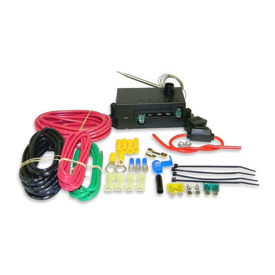
1a. Connect the motor wires to the control module
(Red wire to the "M+" terminal and black wire to
the "M-" terminal).
1b. Disconnect the negative battery lead for
safety while finishing the wiring. Use the large
diameter red (10 AWG) wire to run power directly
from the battery positive (+) terminal to the "B"
terminal on the control module. Connect the fuse
holder in-line with this wire, as shown, but do not
insert the fuse yet. Use the yellow
female, ring, and butt connectors provided.
1c. Use the large diameter black (10 AWG) wire to
run from the negative (-) battery terminal to the "G"
terminal on the control module. Use the yellow
female connector and ring connector provided.
1d. Use the small diameter red wire (14 AWG) to connect the "+" terminal on the
control module to a positive power source. NOTE: Attaching this wire to an
ignition-controlled source will shut off the fan when the engine is turned
off. Attach this wire to an uninterrupted (always hot) power source to allow
the fan to continue running after the engine is shut off. Use the blue female
connector and fuse taps (included) if necessary.
Part number 31149
Temp. Control Module
Wiring Diagram
10-07-05 part no. 99842 Page 1 of 2
Advertisement
Table of Contents

Related Manuals for Flex-a-Lite 31149

Summary of Contents for Flex-a-Lite 31149
-
Page 1: Wiring Diagram
Part number 31149 Temp. Control Module Wiring Diagram 1a. Connect the motor wires to the control module (Red wire to the "M+" terminal and black wire to the "M-" terminal). 1b. Disconnect the negative battery lead for safety while finishing the wiring. Use the large diameter red (10 AWG) wire to run power directly from the battery positive (+) terminal to the "B"... - Page 2 Flex-a-lite Consolidated, 7213-45th St. Ct. E. Fife, WA 98424, Telephone No. 253-922-2700, warrants to the original purchasing user, that all Flex-a-lite products to be free of defects in material and workmanship for a period of 365 days (1 year) from date of purchase. Flex-a-lite products failing within 365 days (1 year) from date of purchase may be returned to the factory through the point of purchase, transportation charges prepaid.
Need help?
Do you have a question about the 31149 and is the answer not in the manual?
Questions and answers