Table of Contents
Advertisement
Quick Links
User's Guide
ADI-8 QS
The Professional's Converter Solution
™
™
I64 Option Slot
TotalRemote
™
™
™
SteadyClock
SyncCheck
FlexGain
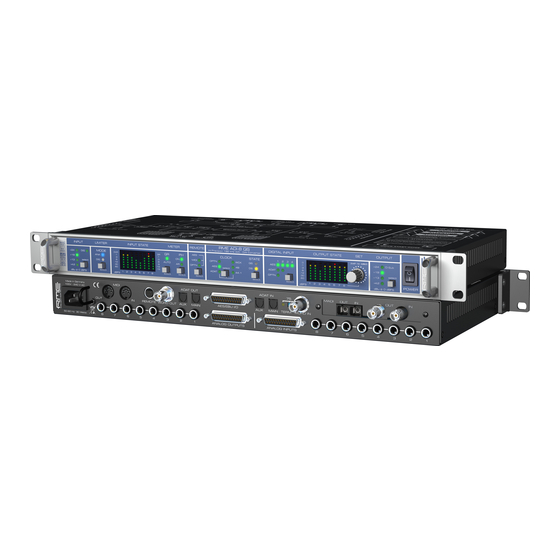
Professional 8-Channel AD/DA Converter
Reference Low Latency Conversion
8-Channel Analog <> AES / ADAT Interface
Optional 64-Channel MADI Interface
24 Bit / 192 kHz Digital Audio
MIDI Remote Control
AES-3
AES-10
24 Bit Interface
Advertisement
Table of Contents

Related Manuals for RME Audio ADI-8 QS


Summary of Contents for RME Audio ADI-8 QS
- Page 1 User’s Guide ADI-8 QS The Professional’s Converter Solution ™ ™ I64 Option Slot TotalRemote ™ ™ ™ SteadyClock SyncCheck FlexGain Professional 8-Channel AD/DA Converter Reference Low Latency Conversion 8-Channel Analog <> AES / ADAT Interface Optional 64-Channel MADI Interface 24 Bit / 192 kHz Digital Audio MIDI Remote Control AES-3 AES-10...
-
Page 2: Table Of Contents
9.12 Global Output Level Enable (GE) ......21 9.13 Direct Level (dL)...........21 9.14 Effects (FX) ............21 9.15 Digital to Digital (dd)..........22 Remote Control 10.1 Hardware Remote ..........23 10.2 MIDI..............23 10.3 MIDI over MADI............23 10.4 Remote Control Software........24 User’s Guide ADI-8 QS © RME... - Page 3 17.7 Signal to Noise ratio in DS / QS Operation..51 17.8 MADI Basics ............52 17.9 SteadyClock............53 Block Diagram............54 MIDI Implementation ADI-8 QS 19.1 Basic SysEx Format ..........55 19.2 Message Types ........... 55 19.3 Table ..............56 User’s Guide ADI-8 QS © RME...
-
Page 4: Important Safety Instructions
When mounting in a rack, leave some space between this device and others for ventilation. Unauthorized servicing/repair voids warranty. Only use accessories specified by the manufacturer. Read the manual completely. It includes all information necessary to use and operate this device. User’s Guide ADI-8 QS © RME... -
Page 5: General
User’s Guide ADI-8 QS General User’s Guide ADI-8 QS © RME... -
Page 6: Introduction
1. Introduction RME's ADI-8 QS is an 8-channel high-end AD/DA converter with a truly unique feature set. The device combines excellent analog circuit design with the latest generation of outstanding low latency AD/DA converter chips. Along with its integrated SteadyClock, the ADI-8 QS offers AD and DA conversion of the highest quality. -
Page 7: First Usage - Quick Start
Setup menu. The key ANALOG OUT defines the analog reference level at the analog outputs. This level is reached at full scale of the AD-converters, thus matching the front panel level meter's level indi- cation. User’s Guide ADI-8 QS © RME... - Page 8 With installed I64 MADI Card: MADI I/O optical: Standard MADI ports. MADI I/O koaxial (BNC): Standard MADI ports. User’s Guide ADI-8 QS © RME...
-
Page 9: Quick Start
On the DA-side just choose the desired digital input by pressing DIGITAL INPUT. A coarse correction of the analog output level can be done by pressing the OUTPUT button. The ADI-8 QS stores all current settings and automatically activates them when the device is turned on. User’s Guide ADI-8 QS © RME... -
Page 10: Accessories
5. Accessories RME offers several optional components for the ADI-8 QS: Part Number Description OK0050 Optical cable, Toslink, 0.5 m (1.7 ft) OK0100 Optical cable, Toslink, 1 m (3.3 ft) OK0200 Optical cable, Toslink, 2 m (6.6 ft) OK0300 Optical cable, Toslink, 3 m (9.9 ft) OK0500 Optical cable, Toslink, 5 m 16.4 ft) -
Page 11: Warranty
All entries in this User’s Guide have been thoroughly checked, however no guarantee for cor- rectness can be given. RME cannot be held responsible for any misleading or incorrect informa- tion provided throughout this manual. Lending or copying any part or the complete manual or its contents as well as the software belonging to it is only possible with the written permission from RME. - Page 12 For this the device has to be sent free to the door to: IMM Elektronik GmbH Leipziger Straße 32 D-09648 Mittweida Germany Shipments not prepaid will be rejected and returned on the original sender's costs. User’s Guide ADI-8 QS © RME...
-
Page 13: Usage And Operation
User’s Guide ADI-8 QS Usage and Operation User’s Guide ADI-8 QS © RME... -
Page 14: Front Panel Controls Input
(both LEDs lit). Analog Limiter For the ADI-8 QS, RME developed a new fully symmetrical circuit design with digitally controlled release time. While the analog limiter is constantly within the signal path, it operates fully transparent as long as there is no control sig- nal generated, so does not cause noise or distortion. -
Page 15: Input State
SyncCheck compares the incoming data and the ADI-8 QS internal clock. The SYNC state is indicated by a flashing (error) or turned off (OK) LED. User’s Guide ADI-8 QS © RME... -
Page 16: Digital Input
Setup menu. Pushing the knob SET activates the Setup menu. Within the Setup menu a push on SET changes between left and right window. User’s Guide ADI-8 QS © RME... -
Page 17: Output
LED in the left window. The more LEDs light up, the higher is the output level. At 0 dB at- tenuation all 48 LEDs are lit. In the range of 0 db down to –20 dB the attenuation takes place in steps of 1 dB. User’s Guide ADI-8 QS © RME... -
Page 18: Input Trim
ID 1: channels 1-8 ID 4: channels 25-32 ID 7: channels 49-56 ID 2: channels 9-16 ID 5: channels 33-40 ID 8: channels 57-64 ID 3: channels 17-24 ID 6: channels 41-48 User’s Guide ADI-8 QS © RME... -
Page 19: Bank (Ba)
2 and 3 are delayed by 6 and 3 samples respectively. At Double Speed and Quad Speed the values rise. Please note that in Double Speed no more than four, in Quad Speed no more than two ADI-8 QS can be used serially with MADI. User’s Guide ADI-8 QS © RME... -
Page 20: Follow Clock (Fc)
S/MUX method the device else can not know which of the incoming 2 (DS) or 4 (QS) word clock edges is the right one. * With the ADI-8 QS this limitation is also valid for the AES output, as the device internally handles all the data streams in S/MUX mode. User’s Guide ADI-8 QS © RME... -
Page 21: Trim Enable (Te)
I/O ratio curve of a limiter. The picture to the left shows the setting 1.5 dB, having the smallest effect. At 5 dB the curve is more horizontal, indicating a stronger influence on the input signal. User’s Guide ADI-8 QS © RME... -
Page 22: Digital To Digital (Dd)
– when activated – by the digital limiter, before finally reaching the digital outputs. The block diagrams show the signal flow for both modes. Digital to Digital - Direct Digital to Digital - Effects User’s Guide ADI-8 QS © RME... -
Page 23: Remote Control
So what about MIDI? Be it remote control commands or sequencer data, in practice only a single MADI line will not suffice. Therefore RME developed a MIDI over MADI technol- ogy. The data at the MIDI input are being included into the MADI signal invisibly, and can be collected at the MIDI output of another ADI-8 QS, ADI-6432, ADI-642, ADI-648, Micstasy or a HDSP MADI, at the other end of the MADI line. -
Page 24: Remote Control Software
MADI to the ADI-8 QS. 10.4 Remote Control Software A software can be downloaded for free from the RME website. It can use any existing MIDI port within the system to perform remote control and status requests of any number of ADI-8 QS via a simple mouse click. - Page 25 REMOTE key. In Off-state Lock Keys is deactivated. Therefore a locking of all the controls can be revoked directly at the unit at any time. The software MIDI Remote also controls RME's ADI-648, ADI- 6432, ADI-642, Micstasy, the complete M-series MADI Bridge. User’s Guide ADI-8 QS © RME...
- Page 26 User’s Guide ADI-8 QS © RME...
-
Page 27: Inputs And Outputs
User’s Guide ADI-8 QS Inputs and Outputs User’s Guide ADI-8 QS © RME... -
Page 28: Analog Inputs / Outputs
The red LED OVR lights up 0.2 dB before full scale level (-0.2 dBFS). The ADI-8 QS uses the following level references: Reference 0 dBFS @ Headroom @ +4 dBu Other RME devices +24 dBu 20 dB +19 dBu... -
Page 29: Line Out
The different output levels guarantee optimal conversion results, while still being compatible to any attached analog equipment. The ADI-8 QS uses the following level references: Reference 0 dBFS @ Headroom @ +4 dBu Other RME devices +24 dBu 20 dB +19 dBu 15 dB... -
Page 30: Digital Inputs / Outputs
2 channels per AES wire. The effective sample frequency equals the clock on the AES wire. In case a conversion from/to Single, Double and Quad Wire is required, the RME ADI-192 DD, an 8-channel universal sample rate and format converter, is highly recommended. -
Page 31: Adat Optical
Speed or two channels at Quad Speed, the port labeled AUX has to be used as well. The ADAT optical inputs of the ADI-8 QS use RME's unsurpassed Bitclock PLL, which prevents clicks and drop outs even in extreme varipitch operation, and guarantees a fast and low jitter lock to the digital input signal. -
Page 32: I64 Madi Card
The diagram on the next page shows a serial setup with HDSP MADI card, three ADI-8 QS and activated Delay Compensation. Delay Compensation has to be manually activated in each unit! User’s Guide ADI-8 QS © RME... -
Page 33: Differences I64 Madi Card / Adi-642
ID, and with this the according channel routing. Mixed setups: Auto ID and Auto are compatible. In contrast (A)DC is automatic only with the 642. The ADI-8 QSs require to activate Delay Compensation manually in each unit. User’s Guide ADI-8 QS © RME... -
Page 34: Word Clock
As soon as a valid signal is detected, the WCK LED is constantly lit, oth- erwise it is flashing. Thanks to RME's Signal Adaptation Circuit, the word clock input still works correctly even with heavily mis-shaped, dc-prone, too small or overshoot-prone signals. Thanks to automatic signal centering, 300 mV (0.3 V) input level are sufficient in principle. -
Page 35: Technical Description And Background
22 MHz from a slow word clock of 44.1 kHz is no problem anymore. Additionally, jitter on the input signal is highly rejected, so that even in real world usage the re-gained clock signal is of highest quality. User’s Guide ADI-8 QS © RME... -
Page 36: Cables And Termination
T-adapter, but to use the ADI-8 QS word clock output instead. Thanks to SteadyClock, the input signal will both be freed from jitter and - in case of loss or drop out – be held at the last valid frequency. User’s Guide ADI-8 QS © RME... -
Page 37: Midi
10.1. Note: The Hardware Remote uses the function Global Output Level, see chapter 9.2. The vol- ume can not be changed if this option is deactivated in the Setup menu. User’s Guide ADI-8 QS © RME... - Page 38 User’s Guide ADI-8 QS © RME...
-
Page 39: Technical Reference
User’s Guide ADI-8 QS Technical Reference User’s Guide ADI-8 QS © RME... -
Page 40: Technical Specifications
Line Out 1-8, D-Sub • Maximum output level: +27 dBu • Output: D-sub 25-pin, electronically balanced • Output impedance: 150 Ohm • Output level switchable +4.2 dBu, +13 dBu, +19 dBu, +24 dBu @ 0 dBFS User’s Guide ADI-8 QS © RME... -
Page 41: Digital Inputs
• Quad Wire: up to 16 channels 24 bit 192 kHz • Lock range: 28 kHz – 54 kHz • Jitter when synced to input signal: < 1 ns • Jitter suppression: > 30 dB (2.4 kHz) User’s Guide ADI-8 QS © RME... -
Page 42: Digital Outputs
• Supported sample rates: 28 kHz up to 200 kHz 15.5 MIDI • 16 channels MIDI • 5-pin DIN jacks • Optocoupled, ground-free input I64 MADI Card • Invisible transmission via User bit of channel 56 (48k frame) User’s Guide ADI-8 QS © RME... -
Page 43: General
(date code sticker). 15.8 MADI User Bit Chart • RS-232: channels 1 to 9 (through mode active in the I64 MADI Card) • ADC: channel 19 • MIDI: channel 56 (48k) / 28 (96k) User’s Guide ADI-8 QS © RME... -
Page 44: Connector Pinouts
3/4- 5/6+ 5/6- 7/8+ 7/8- D-Sub Signal 1/2+ 1/2- 3/4+ 3/4- 5/6+ 5/6- 7/8+ 7/8- D-Sub GND is connected to pins 3, 6, 9, 12, 14, 17, 20, 23. Pin 1 is not connected. User’s Guide ADI-8 QS © RME... - Page 45 Ring = – (cold) Sleeve = GND The servo-balanced circuitry allows to use monaural TS jacks (unbalanced) with no loss in level. This is the same as when using a TRS-jack with ring connected to ground. User’s Guide ADI-8 QS © RME...
-
Page 46: Technical Background
The Quad Wire method realizes the transmission of two channels at up to 192 kHz via ADAT. The method is referred to as S/MUX4. Note: All conversions of the described methods are lossless. The existing samples are just spread or re-united between the channels. User’s Guide ADI-8 QS © RME... -
Page 47: Lock And Synccheck
In practice, SyncCheck allows for a quick overview of the correct configuration of all digital de- vices. This way one of the most difficult and error-prone topics of the digital studio world finally becomes easy to handle. User’s Guide ADI-8 QS © RME... -
Page 48: Latency And Monitoring
16.3 Latency and Monitoring The term Zero Latency Monitoring has been introduced by RME in 1998 for the DIGI96 series and describes the ability to pass-through the computer's input signal at the interface directly to the output. Since then, the idea behind has become one of the most important features of mod- ern hard disk recording. -
Page 49: Ds - Double Speed
An implementation of the ADAT format as double S/MUX (S/MUX4) results in only two channels per optical output. Therefore in Quad Speed mode the ADI-8 QS is limited to 4 chan- nels at the ADAT outputs. The AES outputs provide 192 kHz as Single Wire only. User’s Guide ADI-8 QS © RME... -
Page 50: Aes/Ebu - Spdif
The table shows that a Professional-coded signal would lead to malfunctions for copy prohibi- tion and emphasis, if being read as Consumer-coded data. Nowadays many devices with SPDIF input can handle Professional subcode. Devices with AES3 input almost always accept Consumer SPDIF (passive cable adapter required). User’s Guide ADI-8 QS © RME... -
Page 51: Signal To Noise Ratio In Ds / Qs Operation
When limiting the measurement range from 20 Hz to 20 kHz (so called audio bandpass) the value would be -114 dB again. This can be verified with RME's DIGICheck. The function Bit Statistic & Noise measures the noise floor by Limited Bandwidth, ignoring DC and ultrasound. -
Page 52: Madi Basics
2 km. Single mode allows for much longer distances, but it uses a completely different fibre (8 µm). Due to the wave-length of the light being used (1300 nm) the optical signal is invisible to the human eye. User’s Guide ADI-8 QS © RME... -
Page 53: Steadyclock
Latest circuit designs like hi-speed digital synthesizer, digital PLL, 100 MHz sample rate and analog filtering allow RME to realize a completely newly developed clock technology, right within the FPGA at lowest costs. The clock's performance exceeds even professional expectations. -
Page 54: Block Diagram
17. Block Diagram User’s Guide ADI-8 QS © RME... -
Page 55: Midi Implementation Adi-8 Qs
F0 00 20 0D 41 (bank no. / dev ID) 31 (AD ch.1) (ch.2) (ch.3) (ch.4) (ch.5) (ch.6) (ch.7) (ch.8) (DA ch.1) (ch.2) (ch.3) (ch.4) (ch.5) (ch.6) (ch.7) (ch.8) F7 The peak level value will be stored and transmitted with the next level meter data request, and the stored value will be reset. User’s Guide ADI-8 QS © RME... -
Page 56: Table
-48, -46, -44, -42, -40, -38, -36, -34, -32, -30, -28, -26, -24, 14..28 -22, -20 -19, -18, -17, -16, -15, -14, -13, -12, -11, -10, -9, -8, -7, -6, - 29..47 5, -4, -3, -2, -1 User’s Guide ADI-8 QS © RME... - Page 57 0 = disable, 1 = enable LSB / 0 display mode: 0 = normal, 1 = auto gain reduction MSB / Setup 5 LSB / 0 dd: 0 = di, 1 = fx User’s Guide ADI-8 QS © RME...
- Page 58 1 = < -30dBFS, 2 = < -12dBFS level: 3 = < -6dBFS, 4 = < -3dBFS, 5 = < -1dBFS LSB / 0 LSB / 0 level: 6 = < 0dBFS, 7 = over User’s Guide ADI-8 QS © RME...
Need help?
Do you have a question about the ADI-8 QS and is the answer not in the manual?
Questions and answers