Advertisement
WARRANTY VALIDATION
PLEASE FILL OUT THIS FORM
AND MAIL IT IN TO REGISTER YOUR WARRANTY
Your Name ________________________________________
Address ________________________________________
________________________________________
Email Address _________________________________
Dealer Name ____________________________________
Address ________________________________________
________________________________________
Date of Purchase ___/___/___ Model # __________
Make/Model of Car ______________________________
Year of Car _____
V.I.N. # ____________________
Final Quality Check By _________________________
Mail to: JBS Technologies
225 Technology Way • Steubenville, Ohio 43952
PROGRAMMING FUNCTIONS
FOR YOUR WALLET OR GLOVE BOX
ATTENTION:
We urge you to immediately place this card in your wallet.
Adding Additional Remotes
The hood must be open or the hood pin wire must be grounded. Then,
press and hold Button #1 on the working transmitter for ten (10)
seconds or until the ignition relay clicks or the check engine
light flashes once, release Button #1. Press and release any button
on the new remote control. The ignition relay will click or the
check engine light will flash three (3) times. Close the hood or
remove the hood pin wire from ground and try both remotes.
Tach/Tachless Option The brake must be depressed.
Press and hold Button #1 for 5 seconds or until the ignition relay
clicks or the check engine light flashes once. Release. Press and
release Button #1, the ignition relay clicks or the check engine
light flashes once. The unit is now programmed for Tachless Mode.
Press and release Button #2, the ignition relay clicks or the check
engine light flashes twice. The unit is now programmed for Tach
Mode. NOTE: The factory setting is Tachless Mode.
22
CONTENTS
System Features .......................
System Components ..................... 4
Required Tools ........................
Technical Assistance................. 4-5
Before You Begin ...................... 5
Precautions...........................
Using your Test Probe.................. 6
Making Wiring Connections ............ 6-8
Locating & Making Connections ....... 8-12
Connecting the Wiring Harness ......... 13
Neutral Safety Switch................. 14
Operator Programming Instructions...... 15
How to use Your Remote Transmitter..... 16
Vehicle Anti-theft System Chart..... 17-20
FCC ID Notice ........................
Important Functions................ 21-22
Warranty Validation .................. 21
Your Warranty ........................
Protected by one or more
of the following patents:
Patent #5,459,477 Patent #5,612,670
Patent #5,886,622 Patent #5,677,664
Patent #5,942,988 Patent #6,101,428
Patent #6,452,772
Other patents pending.
4
4
6
20
23
3
Advertisement
Table of Contents

Related Manuals for Bulldog Security RS79


Summary of Contents for Bulldog Security RS79
-
Page 1: Table Of Contents
WARRANTY VALIDATION CONTENTS PLEASE FILL OUT THIS FORM AND MAIL IT IN TO REGISTER YOUR WARRANTY System Features ....... Your Name ________________________________________ System Components ..... 4 Address ________________________________________ Required Tools ......________________________________________ Technical Assistance....4-5 Email Address _________________________________ Before You Begin ...... 5 Dealer Name ____________________________________ Address ________________________________________ Precautions...... -
Page 2: System Features
SYSTEM FEATURES Two-Button Remotely start your car to run the heater or air Extended Range conditioning from an extended distance. Remote Control Two-Way Capability Works with your factory keyless remote transmitter or the transmitter included with this kit. Parking Light Confirms that your vehicle has received a remote Confirmation signal and will remain on if the engine is remotely... -
Page 3: Before You Begin
It is computer controlled SATURN ALL 97+ FACTORY and manufactured in the U.S.A. The dependability and variety of features make Bulldog Security the leader in the industry. 2000+ TRANSPONDER Enjoy your new remote starter for years to come! TOYOTA... -
Page 4: Precautions
PRECAUTIONS VEHICLES WITH FACTORY ANTI-THEFT SYSTEMS (CONT.) DO NOT use mechanical wiring connections, such as crimp or snap together taps. Follow instructions on page 6-8. Manufacturer Make/ Year Anti-theft DO NOT disconnect the battery if the vehicle has an anti-theft-coded radio or is equipped with an airbag. - Page 5 VEHICLES WITH FACTORY MAKING CONNECTIONS (CONT.) ANTI-THEFT SYSTEMS 4. Insert the wire(s) from the starter through the hole as shown. If two or more wires are inserted, wrap them in opposite directions. Manufacturer Make/ Year Anti-theft MALIBU 97+ PASSLOCK 2 MONTE CARLO 96-99 VATS MONTE CARLO 2000+...
-
Page 6: Locating & Making Connections
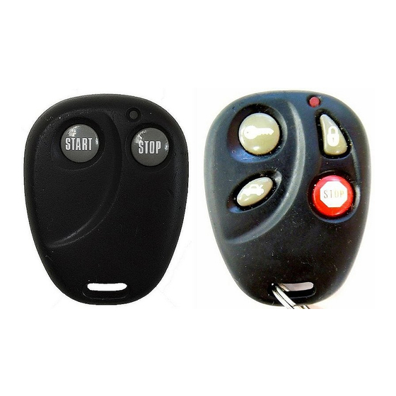
MAKING CONNECTIONS VEHICLES WITH FACTORY (CONT.) ANTI-THEFT SYSTEMS 3. Lay upper twisted pair of wires over right wire as shown. Bring lower twisted pair of wires up to meet the left wire as shown. Manufacturer Make/ Year Anti-theft Acura TL 99+ TRANSPONDER CL 98+ TRANSPONDER... - Page 7 LOCATING & MAKING CONNECTIONS HOW TO USE YOUR NEW REMOTE TRANSMITTER Start IGNITION WIRE(S) (WHITE) and (WHITE WITH RED STRIPE) (+12V in Press and release Button #1 the vehicle run, crank and sometimes accessory) will remote start. Make all connections as close to the ignition switch as possible. The ignition wire(s) are also located in the main harness Stop coming from the ignition switch.
- Page 8 LOCATING & MAKING CONNECTIONS OPERATOR PROGRAMMING INSTRUCTIONS CHASSIS GROUND (BLACK) ADDING ADDITIONAL REMOTES: Locate an easy to get to bolt or screw located under the The hood must be open. If you do not have the hood pin switch driver’s side of the dash and attach the BLACK ground wire installed in the vehicle, you will need to put the hood pin wire from the 9-pin harness securely as pictured.
-
Page 9: Neutral Safety Switch
NEUTRAL SAFETY SWITCH LOCATING & MAKING CONNECTIONS FACTORY ALARM SHUT DOWN WIRE (FASD) (-) (RED WITH BLACK MECHANICAL NEUTRAL SAFETY SWITCH STRIPE) When installing a Bulldog remote starter on GM vehicles or If your vehicle is equipped with a factory alarm system Dodge Dakotas built prior to 1996, you must: (as most vehicles with a factory keyless entry are) or, if your vehicle DOES NOT have a factory remote control... - Page 10 LOCATING & MAKING CONNECTIONS CONNECTING THE 9-PIN HARNESS AUXILIARY INPUT (For your factory keyless or aftermarket alarm) RED 12 V Constant When connecting this unit to a factory keyless entry system, WHITE/BLACK Accessory you must locate the door lock wire that tests as a positive when you press the lock button on the factory remote.
Need help?
Do you have a question about the RS79 and is the answer not in the manual?
Questions and answers